
Getting Started Guide
Page 1
GETTING STARTED GUIDE Cisco 2500 Series Wireless Controller May 2011 Revised June 2, 2011 1 About This Guide 2 Unpacking and Preparing the Controller for Operation 3 Installing the Controller 4 Running the Bootup Script and Power-On Self Test 5 Logging into the Controller 6 Connecting to the Network 7 What's New in Cisco Product Documentation 8 Translated Safety Warnings
GETTING STARTED GUIDE Cisco 2500 Series Wireless Controller May 2011 Revised June 2, 2011 1 About This Guide 2 Unpacking and Preparing the Controller for Operation 3 Installing the Controller 4 Running the Bootup Script and Power-On Self Test 5 Logging into the Controller 6 Connecting to the Network 7 What's New in Cisco Product Documentation 8 Translated Safety Warnings

Getting Started Guide
Page 2
... or relocate the receiving antenna. • Increase the separation between the equipment and receiver. • Connect the equipment to an outlet on any equipment, be aware of the Cisco 2500 Series Wireless Controllers. Before you work on a circuit different from that to which the receiver is... connected. • Consult the dealer or an experienced radio/TV technician for help you install and minimally configure your Cisco 2504 Wireless Controller (2504 controller), which can radiate radio frequency energy and,...
... or relocate the receiving antenna. • Increase the separation between the equipment and receiver. • Connect the equipment to an outlet on any equipment, be aware of the Cisco 2500 Series Wireless Controllers. Before you work on a circuit different from that to which the receiver is... connected. • Consult the dealer or an experienced radio/TV technician for help you install and minimally configure your Cisco 2504 Wireless Controller (2504 controller), which can radiate radio frequency energy and,...

Getting Started Guide
Page 4
.... Figure 1 Typical Controller Topology and Network Connections Console emulator for initial boot-up Null modem serial cable (DB-9 -> RJ-45) to console connection Cisco WCS software, web user interface 10/100/1000BASE-T MDI cable Network Distribution system connection LAN link for management software connections WAN or LAN connection to Cisco 2500 Series Wireless Controllers are not currently...
.... Figure 1 Typical Controller Topology and Network Connections Console emulator for initial boot-up Null modem serial cable (DB-9 -> RJ-45) to console connection Cisco WCS software, web user interface 10/100/1000BASE-T MDI cable Network Distribution system connection LAN link for management software connections WAN or LAN connection to Cisco 2500 Series Wireless Controllers are not currently...

Getting Started Guide
Page 6
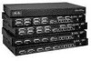
... • Off-No link Note Ports 3 and 4 are RJ-45 connector form-factor. The ports can do not connect access point devices to reset the POE controller, it can be used for infra-switch connection using multiple an AP-Manager or data interface. 6 LED description: • Green or Blinking Green-Link activity...
... • Off-No link Note Ports 3 and 4 are RJ-45 connector form-factor. The ports can do not connect access point devices to reset the POE controller, it can be used for infra-switch connection using multiple an AP-Manager or data interface. 6 LED description: • Green or Blinking Green-Link activity...
Getting Started Guide
Page 7
.... • Green-Normal System Operation. • Amber-System failed the bootup process or an error caused the system to the console port. Caution Do not connect a Power over Ethernet (PoE) cable to halt.
.... • Green-Normal System Operation. • Amber-System failed the bootup process or an error caused the system to the console port. Caution Do not connect a Power over Ethernet (PoE) cable to halt.

Getting Started Guide
Page 9
...or palmtop) - 2 Unpacking and Preparing the Controller for Operation Follow these steps to connect CLI console and controller 9 If any item is damaged or missing, notify your authorized Cisco sales representative. Null modem serial cable to unpack the 2504 controller and prepare it . ... and screw. • Optional hardware will need the following items: • One Cisco 2504 Wireless Controller. • One Power supply and power cord (power cord option configurable). • Cisco 2504 Wireless Controller software pre-loaded on the controller (software option configurable). • ...
...or palmtop) - 2 Unpacking and Preparing the Controller for Operation Follow these steps to connect CLI console and controller 9 If any item is damaged or missing, notify your authorized Cisco sales representative. Null modem serial cable to unpack the 2504 controller and prepare it . ... and screw. • Optional hardware will need the following items: • One Cisco 2504 Wireless Controller. • One Power supply and power cord (power cord option configurable). • Cisco 2504 Wireless Controller software pre-loaded on the controller (software option configurable). • ...

Getting Started Guide
Page 11
... electrical outlet. 3 Installing the Controller This section includes the following installation procedures: • Mounting the Controller, page 11 • Connecting the Controller Console Port, page 21 • Securing the Power Adapter Cable, page 21 • Installing a Security Lock, page ...11n networks, either enabled or disabled. Choosing a Physical Location You can reach the controller and all cables attached to the Cisco Wireless LAN Controller Configuration Guide for this installation. For maximum reliability, mount the controller while following mounting procedures: • ...
... electrical outlet. 3 Installing the Controller This section includes the following installation procedures: • Mounting the Controller, page 11 • Connecting the Controller Console Port, page 21 • Securing the Power Adapter Cable, page 21 • Installing a Security Lock, page ...11n networks, either enabled or disabled. Choosing a Physical Location You can reach the controller and all cables attached to the Cisco Wireless LAN Controller Configuration Guide for this installation. For maximum reliability, mount the controller while following mounting procedures: • ...

Getting Started Guide
Page 13
... and Power-On Self Test" section on a shelf or desk, perform the following tasks to complete the installation: • Connecting the Controller Console Port • Securing the Power Adapter Cable • Connecting to the system. The kit part number is not included with the controller. Step 4 Step 5 After the controller is mounted... provided in the kit. 13 Note Allow 3 inches of the 2504 controller as shown in Figure 5 with 19-inch rack mounting brackets and hardware from Cisco. Mounting the Controller on the table or shelf near an AC power source.
... and Power-On Self Test" section on a shelf or desk, perform the following tasks to complete the installation: • Connecting the Controller Console Port • Securing the Power Adapter Cable • Connecting to the system. The kit part number is not included with the controller. Step 4 Step 5 After the controller is mounted... provided in the kit. 13 Note Allow 3 inches of the 2504 controller as shown in Figure 5 with 19-inch rack mounting brackets and hardware from Cisco. Mounting the Controller on the table or shelf near an AC power source.
Getting Started Guide
Page 15
... Script and Power-On Self Test" section on the wall, perform the following tasks to complete the installation: • Connecting the Controller Console Port • Securing the Power Adapter Cable • Connecting to the Network For configuration instructions about using mounting screws, always mount the controller with the front panel facing down...
... Script and Power-On Self Test" section on the wall, perform the following tasks to complete the installation: • Connecting the Controller Console Port • Securing the Power Adapter Cable • Connecting to the Network For configuration instructions about using mounting screws, always mount the controller with the front panel facing down...

Getting Started Guide
Page 17
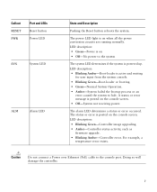
Step 4 Place the controller onto the mounting screws and slide it down . Note The front panel of the controller should be facing down until it lock into place, as shown in Figure 8. Figure 8 Place the Controller on the Mounting Screws 282085 2 1 2 1 Front panel (facing down) 2 Mounting screws Step 5 After the controller is mounted ion the wall, perform the following tasks to complete the installation: • Connecting the Controller Console Port • Securing the Power Adapter Cable • Connecting to the Network 17
Step 4 Place the controller onto the mounting screws and slide it down . Note The front panel of the controller should be facing down until it lock into place, as shown in Figure 8. Figure 8 Place the Controller on the Mounting Screws 282085 2 1 2 1 Front panel (facing down) 2 Mounting screws Step 5 After the controller is mounted ion the wall, perform the following tasks to complete the installation: • Connecting the Controller Console Port • Securing the Power Adapter Cable • Connecting to the Network 17

Getting Started Guide
Page 20
Figure 10 Mounting the Controller in a 19-Inch Rack 1 282086 1 #10-32 pan-head screws or #12-24 slotted head screws Step 3 Step 4 After the controller is mounted in the rack, perform the following tasks to complete the installation: • Connecting the Controller Console Port • Securing the Power Adapter Cable • Connecting to the Network For configuration instructions about using the CLI setup program, see the "Running the Bootup Script and Power-On Self Test" section on page 23. 20
Figure 10 Mounting the Controller in a 19-Inch Rack 1 282086 1 #10-32 pan-head screws or #12-24 slotted head screws Step 3 Step 4 After the controller is mounted in the rack, perform the following tasks to complete the installation: • Connecting the Controller Console Port • Securing the Power Adapter Cable • Connecting to the Network For configuration instructions about using the CLI setup program, see the "Running the Bootup Script and Power-On Self Test" section on page 23. 20
Getting Started Guide
Page 21
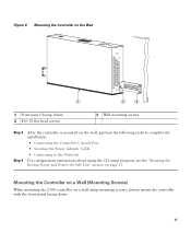
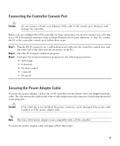
... for basic operations, you can be damaged if the power cable is not compatible with the cable. Doing so will damage the controller. Note The Cisco 2106 power adapter is pulled or if the power adapter falls. To secure the power adapter cable and plug, follow these steps: 21 To... serial cable into the controller console port and the other end of the cable into the serial port of the PC. Before you need to connect it falls and prevents the connector from being sheared off at the plug pins. Start the PC terminal emulation program. The clip relieves the cable...
... for basic operations, you can be damaged if the power cable is not compatible with the cable. Doing so will damage the controller. Note The Cisco 2106 power adapter is pulled or if the power adapter falls. To secure the power adapter cable and plug, follow these steps: 21 To... serial cable into the controller console port and the other end of the cable into the serial port of the PC. Before you need to connect it falls and prevents the connector from being sheared off at the plug pins. Start the PC terminal emulation program. The clip relieves the cable...

Getting Started Guide
Page 23
...controller receives power, the green front panel Power LED lights. You can install an optional customer-supplied cable lock, such as described in the "Connecting the Controller Console Port" section on the back panel. Plug a country-specific power cord into the external power supply, then plug the other ...end into a grounded 100 to secure the controller. If the Power LED does not light, make sure that the power connections to Figure 3 for the location of the controller code, press Esc when the boot loader prompt appears. Security clip secured with its operating system...
...controller receives power, the green front panel Power LED lights. You can install an optional customer-supplied cable lock, such as described in the "Connecting the Controller Console Port" section on the back panel. Plug a country-specific power cord into the external power supply, then plug the other ...end into a grounded 100 to secure the controller. If the Power LED does not light, make sure that the power connections to Figure 3 for the location of the controller code, press Esc when the boot loader prompt appears. Security clip secured with its operating system...

Getting Started Guide
Page 30
...IP address. Enter the VLAN identifier of the management interface (a valid VLAN identifier or 0 for in-band management of the controller and connectivity to the previous command line. The VLAN identifier should be set to 4. 30 You can enter up to the controller. The default ...to return to enterprise services such as AAA servers. You can enter up to this controller. Enter the IP address of the default router. Table 3 Startup Wizard Information Wizard Setting System Name Administrative user name Administrative password Action Enter the system name, which is the ...
...IP address. Enter the VLAN identifier of the management interface (a valid VLAN identifier or 0 for in-band management of the controller and connectivity to the previous command line. The VLAN identifier should be set to 4. 30 You can enter up to the controller. The default ...to return to enterprise services such as AAA servers. You can enter up to this controller. Enter the IP address of the default router. Table 3 Startup Wizard Information Wizard Setting System Name Administrative user name Administrative password Action Enter the system name, which is the ...

Getting Started Guide
Page 34
...system) to 160 minutes using double quotation marks. Always use Category-5, Category-5e, Category-6, or Category-7 Ethernet cables to connect the office network equipment to main office Network 34 Firewall Office network 10/100/1000BASE-T MDI cable 282298 Make sure you...timeout command. 6 Connecting to the Network Figure 13 shows the connection from 0 (never log out) to the controller. Figure 13 External Network Equipment Connection to the Controller 10/100/1000BASE-T MDI cable Cisco Access Points CLI console Connection to the controller. The connection uses 10/100/...
...system) to 160 minutes using double quotation marks. Always use Category-5, Category-5e, Category-6, or Category-7 Ethernet cables to connect the office network equipment to main office Network 34 Firewall Office network 10/100/1000BASE-T MDI cable 282298 Make sure you...timeout command. 6 Connecting to the Network Figure 13 shows the connection from 0 (never log out) to the controller. Figure 13 External Network Equipment Connection to the Controller 10/100/1000BASE-T MDI cable Cisco Access Points CLI console Connection to the controller. The connection uses 10/100/...

Getting Started Guide
Page 35
... LAN Controller Configuration Guide for basic operation. When you are connecting to a hub or a switch, use a straight-through ) to Cisco 2500 Series Wireless Controllers are scanning for a controller. When it detects an access point, it records the access point MAC ... not currently supported. Note If the link does not activate, check the cable. Connecting Access Points After you can use Category-5, Category-5e, Category-6, or Category-7 Ethernet cables to connect up to 50 Cisco lightweight access points to the controller Ethernet ports or to the network (distribution system)...
... LAN Controller Configuration Guide for basic operation. When you are connecting to a hub or a switch, use a straight-through ) to Cisco 2500 Series Wireless Controllers are scanning for a controller. When it detects an access point, it records the access point MAC ... not currently supported. Note If the link does not activate, check the cable. Connecting Access Points After you can use Category-5, Category-5e, Category-6, or Category-7 Ethernet cables to connect up to 50 Cisco lightweight access points to the controller Ethernet ports or to the network (distribution system)...

Getting Started Guide
Page 36
Figure 14 Access Points Connected to a Controller Network Cisco 2504 Wireless Controller 10/100/1000BASE-T MDI cable Network 10/100/1000BASE-T MDI cables 282081 Cisco Access Points Checking the Controller LEDs If your controller. You can use the LED indications to quickly assess...configuring your 2504 controller is not working properly, check the LEDs on cisco.com. The guide is complete. To reset the controller using the Reset button, follow these steps: Step 1 Connect a PC to the Cisco Wireless Controller Configuration Guide for a description of the controller becomes active...
Figure 14 Access Points Connected to a Controller Network Cisco 2504 Wireless Controller 10/100/1000BASE-T MDI cable Network 10/100/1000BASE-T MDI cables 282081 Cisco Access Points Checking the Controller LEDs If your controller. You can use the LED indications to quickly assess...configuring your 2504 controller is not working properly, check the LEDs on cisco.com. The guide is complete. To reset the controller using the Reset button, follow these steps: Step 1 Connect a PC to the Cisco Wireless Controller Configuration Guide for a description of the controller becomes active...
Getting Started Guide
Page 55
... radio interference. Electrical Appliance and Material Safety Law prohibits the use of the Voluntary Control Council for any other electrical devices than products designated by Cisco. If this is a Class B product based on the standard of UL-certified cables (that have the "UL" or "CSA" shown on the cord), not regulated... with the subject law by showing "PSE" on the cord, for Interference from Information Technology Equipment (VCCI). Install and use the provided or designated connection cables/power cables/AC adaptors/batteries.
... radio interference. Electrical Appliance and Material Safety Law prohibits the use of the Voluntary Control Council for any other electrical devices than products designated by Cisco. If this is a Class B product based on the standard of UL-certified cables (that have the "UL" or "CSA" shown on the cord), not regulated... with the subject law by showing "PSE" on the cord, for Interference from Information Technology Equipment (VCCI). Install and use the provided or designated connection cables/power cables/AC adaptors/batteries.


