
Installation Guide
Page 3
... LED 1-8 System LED 1-9 Alarm LED 1-9 Power Status LED 1-9 10/100 Port Status LEDs 1-10 100Base-FX Port Status LEDs 1-10 Dual-Purpose Port LEDs 1-11 Compact Flash Memory Card 1-11 Rear-Panel Description 1-12 Power Converter (Optional) 1-13 Management Options 1-14 Network Configurations 1-15 Switch Installation 2-1 Preparing for Installation 2-1 Warnings 2-2 Cisco IE 3000 Switch Hardware Installation Guide iii
... LED 1-8 System LED 1-9 Alarm LED 1-9 Power Status LED 1-9 10/100 Port Status LEDs 1-10 100Base-FX Port Status LEDs 1-10 Dual-Purpose Port LEDs 1-11 Compact Flash Memory Card 1-11 Rear-Panel Description 1-12 Power Converter (Optional) 1-13 Management Options 1-14 Network Configurations 1-15 Switch Installation 2-1 Preparing for Installation 2-1 Warnings 2-2 Cisco IE 3000 Switch Hardware Installation Guide iii

Installation Guide
Page 4
...2-5 Adding Modules to the Switch 2-5 Expansion Module Configurations 2-5 Connecting Modules 2-8 Installing or Removing the Compact Flash Memory Card 2-10 Verifying Switch Operation 2-11 Connecting a PC or a Terminal to the Console Port 2-12 Connecting the Protective ...Port 2-42 Connecting to 100BASE-FX Ports 2-43 Connecting the Switch to the Power Converter 2-44 Attaching the Power Converter to the Switch 2-45 Installing the Power Converter on a DIN Rail, Wall, or Rack Adapter 2-46 Connecting the DC Power Clip 2-46 Connecting the Power Converter to an AC Power Source 2-47 Cisco IE 3000 Switch...
...2-5 Adding Modules to the Switch 2-5 Expansion Module Configurations 2-5 Connecting Modules 2-8 Installing or Removing the Compact Flash Memory Card 2-10 Verifying Switch Operation 2-11 Connecting a PC or a Terminal to the Console Port 2-12 Connecting the Protective ...Port 2-42 Connecting to 100BASE-FX Ports 2-43 Connecting the Switch to the Power Converter 2-44 Attaching the Power Converter to the Switch 2-45 Installing the Power Converter on a DIN Rail, Wall, or Rack Adapter 2-46 Connecting the DC Power Clip 2-46 Connecting the Power Converter to an AC Power Source 2-47 Cisco IE 3000 Switch...

Installation Guide
Page 5
... to Recover Passwords 3-5 Finding the Switch Serial Number 3-6 Technical Specifications A-1 Installation In a Hazardous Environment B-1 Preparing for Installation B-1 Warnings B-2 North American Hazardous Location Approval B-5 EMC Environmental Conditions for Products Installed in the European Union B-5 Installation Guidelines B-5 Environment and Enclosure Guidelines: B-5 Other Guidelines B-6 Verifying Package Contents B-7 Adding Modules to the Switch B-8 Cisco IE 3000 Switch Hardware Installation Guide v
... to Recover Passwords 3-5 Finding the Switch Serial Number 3-6 Technical Specifications A-1 Installation In a Hazardous Environment B-1 Preparing for Installation B-1 Warnings B-2 North American Hazardous Location Approval B-5 EMC Environmental Conditions for Products Installed in the European Union B-5 Installation Guidelines B-5 Environment and Enclosure Guidelines: B-5 Other Guidelines B-6 Verifying Package Contents B-7 Adding Modules to the Switch B-8 Cisco IE 3000 Switch Hardware Installation Guide v
Installation Guide
Page 6
... SFP Modules from SFP Module Slots B-44 Connecting to SFP Modules B-45 Connecting to a Dual-Purpose Port B-46 Connecting to 100BASE-FX Ports B-48 Connecting the Switch to the Power Converter B-49 Attaching the Power Converter to the Switch B-49 Installing the Power Converter on a DIN Rail, Wall, or Rack Adapter B-52 Connecting the... the AC Power Cord to the Power Converter B-54 Connecting the Power Converter to a DC Power Source B-57 Applying Power to the Power Converter B-59 Cisco IE 3000 Switch Hardware Installation Guide vi OL-13017-01
... SFP Modules from SFP Module Slots B-44 Connecting to SFP Modules B-45 Connecting to a Dual-Purpose Port B-46 Connecting to 100BASE-FX Ports B-48 Connecting the Switch to the Power Converter B-49 Attaching the Power Converter to the Switch B-49 Installing the Power Converter on a DIN Rail, Wall, or Rack Adapter B-52 Connecting the... the AC Power Cord to the Power Converter B-54 Connecting the Power Converter to a DC Power Source B-57 Applying Power to the Power Converter B-59 Cisco IE 3000 Switch Hardware Installation Guide vi OL-13017-01
Installation Guide
Page 7
... a Crossover Cable C-7 Four Twisted-Pair Cable Pinouts for 1000BASE-T Ports C-7 Adapter Pinouts C-8 Configuring the Switch with the CLI-Based Setup Program D-1 Accessing the CLI from the Console Port D-1 Entering the Initial Configuration Information D-2 IP Settings D-2 Completing the Setup Program D-2 Contents OL-13017-01 Cisco IE 3000 Switch Hardware Installation Guide vii and 100BASE-TX-Compatible Devices C-1 Connecting...
... a Crossover Cable C-7 Four Twisted-Pair Cable Pinouts for 1000BASE-T Ports C-7 Adapter Pinouts C-8 Configuring the Switch with the CLI-Based Setup Program D-1 Accessing the CLI from the Console Port D-1 Entering the Initial Configuration Information D-2 IP Settings D-2 Completing the Setup Program D-2 Contents OL-13017-01 Cisco IE 3000 Switch Hardware Installation Guide vii and 100BASE-TX-Compatible Devices C-1 Connecting...

Installation Guide
Page 12
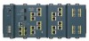
... Switch" section on page 2-5. . Table 1-1 Cisco IE 3000 Switch Models Switch Model Cisco IE-3000-4TC Cisco IE-3000-8TC Cisco IEM-3000-8TM Cisco IEM-3000-8FM Description 4 10/100BASE-T Ethernet ports and 2 dual-purpose ports, each with a 10/100/1000BASE-T copper port and an SFP (small form-factor pluggable) module slot 8 10/100BASE-T Ethernet ports and 2 dual-purpose ports Expansion module with 8 10/100BASE-T copper Ethernet ports Expansion module with 8 100BASE-FX fiber-optic Ethernet ports...
... Switch" section on page 2-5. . Table 1-1 Cisco IE 3000 Switch Models Switch Model Cisco IE-3000-4TC Cisco IE-3000-8TC Cisco IEM-3000-8TM Cisco IEM-3000-8FM Description 4 10/100BASE-T Ethernet ports and 2 dual-purpose ports, each with a 10/100/1000BASE-T copper port and an SFP (small form-factor pluggable) module slot 8 10/100BASE-T Ethernet ports and 2 dual-purpose ports Expansion module with 8 10/100BASE-T copper Ethernet ports Expansion module with 8 100BASE-FX fiber-optic Ethernet ports...

Installation Guide
Page 13
Chapter 1 Overview Figure 1-1 Cisco IE-3000-8TC Switch 1 2 Front-Panel Description 201699 3 45 1 Power and relay connectors 4 10/100 ports 2 Console port 5 Protective ground connection 3 Dual-purpose ports Figure 1-2 Cisco IE-3000-4TC Switch 1 2 201700 3 45 1 Power and relay connectors 4 2 Console port 5 3 Dual-purpose ports 10/100 ports Protective ground connection OL-13017-01 Cisco IE 3000 Switch Hardware Installation Guide 1-3
Chapter 1 Overview Figure 1-1 Cisco IE-3000-8TC Switch 1 2 Front-Panel Description 201699 3 45 1 Power and relay connectors 4 10/100 ports 2 Console port 5 Protective ground connection 3 Dual-purpose ports Figure 1-2 Cisco IE-3000-4TC Switch 1 2 201700 3 45 1 Power and relay connectors 4 2 Console port 5 3 Dual-purpose ports 10/100 ports Protective ground connection OL-13017-01 Cisco IE 3000 Switch Hardware Installation Guide 1-3

Installation Guide
Page 15
... alarm signals to the switch through cable. You can use Gigabit Ethernet SFP modules to establish fiber-optic connections to other switches. Only one port can configure the duplex setting. (See the switch software configuration for more information about these ports for copper Ethernet connections and configures the interfaces accordingly. OL-13017-01 Cisco IE 3000 Switch Hardware Installation Guide 1-5 The...
... alarm signals to the switch through cable. You can use Gigabit Ethernet SFP modules to establish fiber-optic connections to other switches. Only one port can configure the duplex setting. (See the switch software configuration for more information about these ports for copper Ethernet connections and configures the interfaces accordingly. OL-13017-01 Cisco IE 3000 Switch Hardware Installation Guide 1-5 The...

Installation Guide
Page 16
...the CLI to configure and to -DB-9 adapter cable. The relay itself is labeled RT (see Appendix C, "Cable and Connectors." Cisco IE 3000 Switch Hardware Installation Guide 1-6 OL-13017-01 For more information about the power and relay connector, see Figure 1-5). All LEDs are open ... relays: the major and the minor alarms. The relays can be configured to power the switch. Console Port You can be activated for a single switch. Front-Panel Description Chapter 1 Overview The switch accessory pack includes the mating power and relay connectors. If one or with one of the...
...the CLI to configure and to -DB-9 adapter cable. The relay itself is labeled RT (see Appendix C, "Cable and Connectors." Cisco IE 3000 Switch Hardware Installation Guide 1-6 OL-13017-01 For more information about the power and relay connector, see Figure 1-5). All LEDs are open ... relays: the major and the minor alarms. The relays can be configured to power the switch. Console Port You can be activated for a single switch. Front-Panel Description Chapter 1 Overview The switch accessory pack includes the mating power and relay connectors. If one or with one of the...
Installation Guide
Page 17
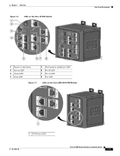
Chapter 1 Overview Figure 1-6 1 2 3 4 LEDs on the Cisco IE 3000 Switch Front-Panel Description 201703 5 67 8 1 Express setup button 2 System LED 3 Alarm LED 4 Setup LED 5 Dual-purpose uplink port LED 6 Pwr B LED 7 Pwr A LED 8 Port LED Figure 1-7 LEDs on the Cisco IEM-3000-8TM Module 201706 1 1 10/100 port LED OL-13017-01 Cisco IE 3000 Switch Hardware Installation Guide 1-7
Chapter 1 Overview Figure 1-6 1 2 3 4 LEDs on the Cisco IE 3000 Switch Front-Panel Description 201703 5 67 8 1 Express setup button 2 System LED 3 Alarm LED 4 Setup LED 5 Dual-purpose uplink port LED 6 Pwr B LED 7 Pwr A LED 8 Port LED Figure 1-7 LEDs on the Cisco IEM-3000-8TM Module 201706 1 1 10/100 port LED OL-13017-01 Cisco IE 3000 Switch Hardware Installation Guide 1-7
Installation Guide
Page 18
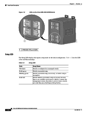
... mode for the initial configuration. Table 1-2 Setup LED Color Off (dark) Solid green Blinking green Solid red Setup Status Switch is no available switch port to which to start initial setup or recovery because there is configured as a managed switch. Cisco IE 3000 Switch Hardware Installation Guide 1-8 OL-13017-01 Table 1-2 lists the LED colors and their meanings...
... mode for the initial configuration. Table 1-2 Setup LED Color Off (dark) Solid green Blinking green Solid red Setup Status Switch is no available switch port to which to start initial setup or recovery because there is configured as a managed switch. Cisco IE 3000 Switch Hardware Installation Guide 1-8 OL-13017-01 Table 1-2 lists the LED colors and their meanings...

Installation Guide
Page 20
...errors, and alignment and jabber errors are monitored for possible loops. 100Base-FX Port Status LEDs These LEDs display information about the individual ports. Link is disabled. 1-10 Cisco IE 3000 Switch Hardware Installation Guide OL-13017-01 Link is present. Error frames can remain ...amber for up to 30 seconds while STP checks the switch for a link-fault indication. Activity. ...
...errors, and alignment and jabber errors are monitored for possible loops. 100Base-FX Port Status LEDs These LEDs display information about the individual ports. Link is disabled. 1-10 Cisco IE 3000 Switch Hardware Installation Guide OL-13017-01 Link is present. Error frames can remain ...amber for up to 30 seconds while STP checks the switch for a link-fault indication. Activity. ...
Installation Guide
Page 21
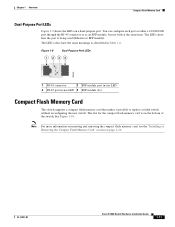
...on a dual-purpose port. The LED colors have the same meanings as an SFP module, but not both at the same time. OL-13017-01 Cisco IE 3000 Switch Hardware Installation Guide 1-11 See Figure 1-10. The slot for the compact flash memory card is being used (Ethernet or SFP module).... Chapter 1 Overview Compact Flash Memory Card Dual-Purpose Port LEDs Figure 1-9 shows the LEDs on page ...
...on a dual-purpose port. The LED colors have the same meanings as an SFP module, but not both at the same time. OL-13017-01 Cisco IE 3000 Switch Hardware Installation Guide 1-11 See Figure 1-10. The slot for the compact flash memory card is being used (Ethernet or SFP module).... Chapter 1 Overview Compact Flash Memory Card Dual-Purpose Port LEDs Figure 1-9 shows the LEDs on page ...
Installation Guide
Page 24
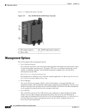
... can fully configure and monitor the switch. Figure 1-12 Cisco IE 3000 Switch AC/DC Power Converter 1 2 3 Chapter 1 Overview 202314 1 DC output connector 2 Status LED 3 AC/DC input power connector Management Options The switch supports these management options: • Cisco Network Assistant Cisco Network Assistant is enhanced to the switch management port, or a console port, or by connecting your network through...
... can fully configure and monitor the switch. Figure 1-12 Cisco IE 3000 Switch AC/DC Power Converter 1 2 3 Chapter 1 Overview 202314 1 DC output connector 2 Status LED 3 AC/DC input power connector Management Options The switch supports these management options: • Cisco Network Assistant Cisco Network Assistant is enhanced to the switch management port, or a console port, or by connecting your network through...
Installation Guide
Page 27
...; Verifying Package Contents, page 2-5 OL-13017-01 Cisco IE 3000 Switch Hardware Installation Guide 2-1 Caution If your switch, interpret the power-on self-test (POST), and connect the switch to Go Next, page 2-53 Preparing for instructions. Switch Installation 2 C H A P T E R This...Switch, page 2-5 • Installing or Removing the Compact Flash Memory Card, page 2-10 • Verifying Switch Operation, page 2-11 • Installing the Switch, page 2-23 • Connecting Power and Alarm Circuits, page 2-32 • Connecting Destination Ports, page 2-36 • Connecting the Switch...
...; Verifying Package Contents, page 2-5 OL-13017-01 Cisco IE 3000 Switch Hardware Installation Guide 2-1 Caution If your switch, interpret the power-on self-test (POST), and connect the switch to Go Next, page 2-53 Preparing for instructions. Switch Installation 2 C H A P T E R This...Switch, page 2-5 • Installing or Removing the Compact Flash Memory Card, page 2-10 • Verifying Switch Operation, page 2-11 • Installing the Switch, page 2-23 • Connecting Power and Alarm Circuits, page 2-32 • Connecting Destination Ports, page 2-36 • Connecting the Switch...
Installation Guide
Page 28
Statement 1001 Warning Before performing any of the following ports must be handled according to install, replace, or service this product should be removed to the terminals. A restricted access area can cause ...rings, necklaces, and watches). All connections must be accessed only through an approved network termination unit with integral circuit protection. 10/100/1000 Ethernet Statement 1044 Cisco IE 3000 Switch Hardware Installation Guide 2-2 OL-13017-01 Metal objects will heat up when connected to power and ground and can be grounded. Statement 1028 ...
Statement 1001 Warning Before performing any of the following ports must be handled according to install, replace, or service this product should be removed to the terminals. A restricted access area can cause ...rings, necklaces, and watches). All connections must be accessed only through an approved network termination unit with integral circuit protection. 10/100/1000 Ethernet Statement 1044 Cisco IE 3000 Switch Hardware Installation Guide 2-2 OL-13017-01 Metal objects will heat up when connected to power and ground and can be grounded. Statement 1028 ...
Installation Guide
Page 30
... can corrode, oxidize, or are poor conductors can be the following minimum clearances: - Cisco IE 3000 Switch Hardware Installation Guide 2-4 OL-13017-01 Note When the switch is installed in an industrial enclosure, the temperature within the ranges listed in Appendix A, "Technical Specifications." • Clearance...yellow-chromate steel DIN rail to ports is sufficient for unrestricted cabling. - Follow the procedures in the "Verifying Switch Operation" section on page 2-11. • For 10/100 ports and 10/100/1000 ports, the cable length from a switch to an attached device cannot ...
... can corrode, oxidize, or are poor conductors can be the following minimum clearances: - Cisco IE 3000 Switch Hardware Installation Guide 2-4 OL-13017-01 Note When the switch is installed in an industrial enclosure, the temperature within the ranges listed in Appendix A, "Technical Specifications." • Clearance...yellow-chromate steel DIN rail to ports is sufficient for unrestricted cabling. - Follow the procedures in the "Verifying Switch Operation" section on page 2-11. • For 10/100 ports and 10/100/1000 ports, the cable length from a switch to an attached device cannot ...
Installation Guide
Page 31
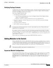
...-14 or equivalent). Adding Modules to the Switch The Cisco IE-3000-4TC or the Cisco IE-3000-8TC switch can be either a Cisco IEM-3000-8TM or a Cisco IEM-3000-8FM. OL-13017-01 Cisco IE 3000 Switch Hardware Installation Guide 2-5 If any item is shipped with four or eight Fast Ethernet ports, respectively. Chapter 2 Switch Installation Adding Modules to the Switch Verifying Package Contents Carefully remove the contents from...
...-14 or equivalent). Adding Modules to the Switch The Cisco IE-3000-4TC or the Cisco IE-3000-8TC switch can be either a Cisco IEM-3000-8TM or a Cisco IEM-3000-8FM. OL-13017-01 Cisco IE 3000 Switch Hardware Installation Guide 2-5 If any item is shipped with four or eight Fast Ethernet ports, respectively. Chapter 2 Switch Installation Adding Modules to the Switch Verifying Package Contents Carefully remove the contents from...

Installation Guide
Page 156
Cisco IE 3000 Switch Hardware Installation Guide C-6 OL-13017-01 Cable and Adapter Specifications Appendix C Cable and Connectors Four Twisted-Pair Cable Pinouts for 1000BASE-T Ports Figure C-7 and Figure C-8 show the schematics of four twisted-pair cables for 10/100/1000 Ports Switch 1 TP0+ 2 TP03 TP1+ 6 TP1- 4 TP2+ 5 TP27 TP3+ 8 TP3- Figure C-7 Switch 1 TPO+ 2 TPO3 TP1+ 6 TP1- Four Twisted...
Cisco IE 3000 Switch Hardware Installation Guide C-6 OL-13017-01 Cable and Adapter Specifications Appendix C Cable and Connectors Four Twisted-Pair Cable Pinouts for 1000BASE-T Ports Figure C-7 and Figure C-8 show the schematics of four twisted-pair cables for 10/100/1000 Ports Switch 1 TP0+ 2 TP03 TP1+ 6 TP1- 4 TP2+ 5 TP27 TP3+ 8 TP3- Figure C-7 Switch 1 TPO+ 2 TPO3 TP1+ 6 TP1- Four Twisted...

Installation Guide
Page 158
...-45-to -DB-9 Terminal Adapter DB-9 Pin 8 6 2 5 5 3 4 7 Console Device Signal CTS DSR RxD GND GND TxD DTR RTS Cisco IE 3000 Switch Hardware Installation Guide C-8 OL-13017-01 Table C-2 Console Port Signaling Using a DB-9 Adapter Switch Console Port (DTE) Signal RTS DTR TxD GND GND RxD DSR CTS RJ-45-to -DB-9 adapter cable, and the console...
...-45-to -DB-9 Terminal Adapter DB-9 Pin 8 6 2 5 5 3 4 7 Console Device Signal CTS DSR RxD GND GND TxD DTR RTS Cisco IE 3000 Switch Hardware Installation Guide C-8 OL-13017-01 Table C-2 Console Port Signaling Using a DB-9 Adapter Switch Console Port (DTE) Signal RTS DTR TxD GND GND RxD DSR CTS RJ-45-to -DB-9 adapter cable, and the console...


