
Installation Guide
Page 12
... "Adding Modules to Figure 1-4 show the switch and expansion module front panels. Switch Models Chapter 1 Overview Switch Models Table 1-1 describes the switch and the expansion modules. Cisco IE 3000 Switch Hardware Installation Guide 1-2 OL-13017-01 Figure 1-1 to the Switch" section on page 2-5. . Table 1-1 Cisco IE 3000 Switch Models Switch Model Cisco IE-3000-4TC Cisco IE-3000-8TC Cisco IEM-3000-8TM Cisco IEM-3000-8FM Description 4 10/100BASE-T Ethernet ports and 2 dual-purpose ports, each...
... "Adding Modules to Figure 1-4 show the switch and expansion module front panels. Switch Models Chapter 1 Overview Switch Models Table 1-1 describes the switch and the expansion modules. Cisco IE 3000 Switch Hardware Installation Guide 1-2 OL-13017-01 Figure 1-1 to the Switch" section on page 2-5. . Table 1-1 Cisco IE 3000 Switch Models Switch Model Cisco IE-3000-4TC Cisco IE-3000-8TC Cisco IEM-3000-8TM Cisco IEM-3000-8FM Description 4 10/100BASE-T Ethernet ports and 2 dual-purpose ports, each...

Installation Guide
Page 13
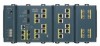
Chapter 1 Overview Figure 1-1 Cisco IE-3000-8TC Switch 1 2 Front-Panel Description 201699 3 45 1 Power and relay connectors 4 10/100 ports 2 Console port 5 Protective ground connection 3 Dual-purpose ports Figure 1-2 Cisco IE-3000-4TC Switch 1 2 201700 3 45 1 Power and relay connectors 4 2 Console port 5 3 Dual-purpose ports 10/100 ports Protective ground connection OL-13017-01 Cisco IE 3000 Switch Hardware Installation Guide 1-3
Chapter 1 Overview Figure 1-1 Cisco IE-3000-8TC Switch 1 2 Front-Panel Description 201699 3 45 1 Power and relay connectors 4 10/100 ports 2 Console port 5 Protective ground connection 3 Dual-purpose ports Figure 1-2 Cisco IE-3000-4TC Switch 1 2 201700 3 45 1 Power and relay connectors 4 2 Console port 5 3 Dual-purpose ports 10/100 ports Protective ground connection OL-13017-01 Cisco IE 3000 Switch Hardware Installation Guide 1-3
Installation Guide
Page 31
... a Cisco IEM-3000-8TM or a Cisco IEM-3000-8FM. You can operate as standalone devices. Adding Modules to 24 Fast Ethernet ports. Depending on a target device by 8 or 16, you need a ring terminal lug (such as Thomas & Bett part number RC10-14 or equivalent). If you can have up to the Switch The Cisco IE-3000-4TC or the Cisco IE-3000-8TC switch can...
... a Cisco IEM-3000-8TM or a Cisco IEM-3000-8FM. You can operate as standalone devices. Adding Modules to 24 Fast Ethernet ports. Depending on a target device by 8 or 16, you need a ring terminal lug (such as Thomas & Bett part number RC10-14 or equivalent). If you can have up to the Switch The Cisco IE-3000-4TC or the Cisco IE-3000-8TC switch can...
Installation Guide
Page 32
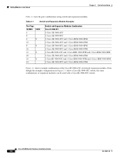
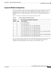
... Modules Combination Cisco IE-3000-4TC 1 Cisco IE-3000-4TC 1 Cisco IE-3000-8TC 1 Cisco IE-3000-4TC and 1 Cisco IEM-3000-8FM 1 Cisco IE-3000-4TC and 1 Cisco IEM-3000-8TM 1 Cisco IE-3000-8TC and 1 Cisco IEM-3000-8FM 1 Cisco IE-3000-8TC and 1 Cisco IEM-3000-8TM 1 Cisco IE-3000-4TC and 1 Cisco IEM-3000-8TM and 1 Cisco IEM-3000-8FM 1 Cisco IE-3000-4TC and 2 Cisco IEM-3000-8TM 1 Cisco IE-3000-8TC and 1 Cisco IEM-3000-8TM and 1 Cisco IEM-3000-8FM 1 Cisco IE-3000-8TC and 2 Cisco IEM-3000-8TM Figure 2-1 shows example combinations of expansion modules can be used with a Cisco IE-3000-8TC switch.
... Modules Combination Cisco IE-3000-4TC 1 Cisco IE-3000-4TC 1 Cisco IE-3000-8TC 1 Cisco IE-3000-4TC and 1 Cisco IEM-3000-8FM 1 Cisco IE-3000-4TC and 1 Cisco IEM-3000-8TM 1 Cisco IE-3000-8TC and 1 Cisco IEM-3000-8FM 1 Cisco IE-3000-8TC and 1 Cisco IEM-3000-8TM 1 Cisco IE-3000-4TC and 1 Cisco IEM-3000-8TM and 1 Cisco IEM-3000-8FM 1 Cisco IE-3000-4TC and 2 Cisco IEM-3000-8TM 1 Cisco IE-3000-8TC and 1 Cisco IEM-3000-8TM and 1 Cisco IEM-3000-8FM 1 Cisco IE-3000-8TC and 2 Cisco IEM-3000-8TM Figure 2-1 shows example combinations of expansion modules can be used with a Cisco IE-3000-8TC switch.
Installation Guide
Page 34
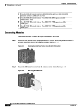
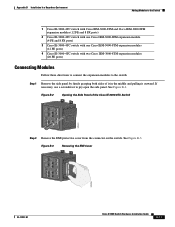
... Cisco IE-3000-8TC Switch 201822 Step 2 Remove the EMI protective cover from the connector on the switch. Figure 2-3 Removing the EMI Cover 203759 Cisco IE 3000 Switch Hardware Installation Guide 2-8 OL-13017-01 See Figure 2-2. Figure 2-2 Opening the Side Panel of it in the middle and pulling it outward. Adding Modules to the Switch Chapter 2 Switch Installation 1 Cisco IE-3000-4TC switch with Cisco IEM-3000-8TM and Cisco...
... Cisco IE-3000-8TC Switch 201822 Step 2 Remove the EMI protective cover from the connector on the switch. Figure 2-3 Removing the EMI Cover 203759 Cisco IE 3000 Switch Hardware Installation Guide 2-8 OL-13017-01 See Figure 2-2. Figure 2-2 Opening the Side Panel of it in the middle and pulling it outward. Adding Modules to the Switch Chapter 2 Switch Installation 1 Cisco IE-3000-4TC switch with Cisco IEM-3000-8TM and Cisco...
Installation Guide
Page 86
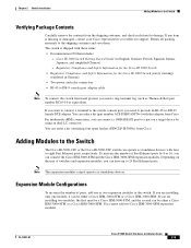
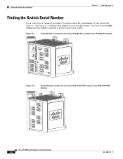
... Number Location for the Cisco IE-3000-4TC and the Cisco IE-3000-8TC Switch SN: XXXNNNNXXXX 202302 Figure 3-2 SN: XXXNNNNXXXX Serial Number Location for the Cisco IEM-3000-8TM and the Cisco IEM-3000-8FM Module 203763 Cisco IE 3000 Switch Hardware Installation Guide 3-6 OL-13017-01 See Figure 3-1 and Figure 3-2 to know the serial number of your switch or module. Finding the Switch Serial Number Chapter 3 Troubleshooting...
... Number Location for the Cisco IE-3000-4TC and the Cisco IE-3000-8TC Switch SN: XXXNNNNXXXX 202302 Figure 3-2 SN: XXXNNNNXXXX Serial Number Location for the Cisco IEM-3000-8TM and the Cisco IEM-3000-8FM Module 203763 Cisco IE 3000 Switch Hardware Installation Guide 3-6 OL-13017-01 See Figure 3-1 and Figure 3-2 to know the serial number of your switch or module. Finding the Switch Serial Number Chapter 3 Troubleshooting...
Installation Guide
Page 88
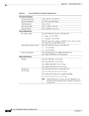
...) Cisco IE-3000-8TC and Cisco IE-3000-4TC: 6 x 4.4 x 5.8 in. (15.4 x 11.2 x 14.7 cm) Cisco IEM-3000-8TM and Cisco IEM-3000-8FM: 3.6 x 4.4 x 5.8 in. (9.1 x 11.2 x 14.7 cm) Note Width includes the cosmetic end-caps. Depth is an SELV circuit, and it can only be connected to another SELV circuit. Cisco IE 3000 Switch Hardware Installation Guide A-2 OL-13017-01 Cisco IE-3000-8TC and Cisco IE-3000-4TC • 1 A @ 48 VDC • 2 A @ 24 VDC Cisco IE-3000-8TC, Cisco...
...) Cisco IE-3000-8TC and Cisco IE-3000-4TC: 6 x 4.4 x 5.8 in. (15.4 x 11.2 x 14.7 cm) Cisco IEM-3000-8TM and Cisco IEM-3000-8FM: 3.6 x 4.4 x 5.8 in. (9.1 x 11.2 x 14.7 cm) Note Width includes the cosmetic end-caps. Depth is an SELV circuit, and it can only be connected to another SELV circuit. Cisco IE 3000 Switch Hardware Installation Guide A-2 OL-13017-01 Cisco IE-3000-8TC and Cisco IE-3000-4TC • 1 A @ 48 VDC • 2 A @ 24 VDC Cisco IE-3000-8TC, Cisco...

Installation Guide
Page 98
... standalone devices. Cisco IE 3000 Switch Hardware Installation Guide B-8 OL-13017-01 Note The expansion modules cannot operate as standalone devices with four or eight Fast Ethernet ports, respectively. Depending on a target device by 8 or 16, you can have up to the Switch The Cisco IE-3000-4TC or the Cisco IE-3000-8TC switch can connect the Cisco IEM-3000-8TM and the Cisco IEM-3000-8FM expansion...
... standalone devices. Cisco IE 3000 Switch Hardware Installation Guide B-8 OL-13017-01 Note The expansion modules cannot operate as standalone devices with four or eight Fast Ethernet ports, respectively. Depending on a target device by 8 or 16, you can have up to the Switch The Cisco IE-3000-4TC or the Cisco IE-3000-8TC switch can connect the Cisco IEM-3000-8TM and the Cisco IEM-3000-8FM expansion...
Installation Guide
Page 99
...Modules Combination Cisco IE-3000-4TC 1 Cisco IE-3000-4TC 1 Cisco IE-3000-8TC 1 Cisco IE-3000-4TC and 1 Cisco IEM-3000-8FM 1 Cisco IE-3000-4TC and 1 Cisco IEM-3000-8TM 1 Cisco IE-3000-8TC and 1 Cisco IEM-3000-8FM 1 Cisco IE-3000-8TC and 1 Cisco IEM-3000-8TM 1 Cisco IE-3000-4TC and 1 Cisco IEM-3000-8TM and 1 Cisco IEM-3000-8FM 1 Cisco IE-3000-4TC and 2 Cisco IEM-3000-8TM 1 Cisco IE-3000-8TC and 1 Cisco IEM-3000-8TM and 1 Cisco IEM-3000-8FM 1 Cisco IE-3000-8TC and 2 Cisco IEM-3000-8TM Figure B-1 shows example combinations of expansion modules can be used with a Cisco IE-3000-8TC switch. If you...
...Modules Combination Cisco IE-3000-4TC 1 Cisco IE-3000-4TC 1 Cisco IE-3000-8TC 1 Cisco IE-3000-4TC and 1 Cisco IEM-3000-8FM 1 Cisco IE-3000-4TC and 1 Cisco IEM-3000-8TM 1 Cisco IE-3000-8TC and 1 Cisco IEM-3000-8FM 1 Cisco IE-3000-8TC and 1 Cisco IEM-3000-8TM 1 Cisco IE-3000-4TC and 1 Cisco IEM-3000-8TM and 1 Cisco IEM-3000-8FM 1 Cisco IE-3000-4TC and 2 Cisco IEM-3000-8TM 1 Cisco IE-3000-8TC and 1 Cisco IEM-3000-8TM and 1 Cisco IEM-3000-8FM 1 Cisco IE-3000-8TC and 2 Cisco IEM-3000-8TM Figure B-1 shows example combinations of expansion modules can be used with a Cisco IE-3000-8TC switch. If you...
Installation Guide
Page 101
... Cisco IE-3000-8TC Switch 201822 Step 2 Remove the EMI protective cover from the connector on the switch. Figure B-2 Opening the Side Panel of it in the middle and pulling it outward. Appendix B Installation In a Hazardous Environment Adding Modules to the Switch 1 Cisco IE-3000-4TC switch with Cisco IEM-3000-8TM and Cisco IEM-3000-8FM expansion modules (12 FE and 8 FX ports) 2 Cisco IE-3000-4TC switch with one Cisco...
... Cisco IE-3000-8TC Switch 201822 Step 2 Remove the EMI protective cover from the connector on the switch. Figure B-2 Opening the Side Panel of it in the middle and pulling it outward. Appendix B Installation In a Hazardous Environment Adding Modules to the Switch 1 Cisco IE-3000-4TC switch with Cisco IEM-3000-8TM and Cisco IEM-3000-8FM expansion modules (12 FE and 8 FX ports) 2 Cisco IE-3000-4TC switch with one Cisco...
Installation Guide
Page 167
... area for installation B-4 power and relay connector B-3, B-24 substitution of components B-4 HP OpenView 1-15 humidity A-2 I IE-3000-4TC switch, illustrated 1-3 IE-3000-8TC switch, illustrated 1-3 IEM-3000-8FM module, illustrated 1-4 IEM-3000-8TM module, illustrated 1-4 industrial environment warning B-4 installation assigning the IP address D-2 attach the power and relay connector 2-21, B-24 compact flash memory... 2-6, B-9 connecting 2-8, B-11 mounting rack 2-29 to 2-31, B-33 to B-35 MT-RJ connector C-3 See also 100BASE-FX ports Cisco IE 3000 Switch Hardware Installation Guide IN-3
... area for installation B-4 power and relay connector B-3, B-24 substitution of components B-4 HP OpenView 1-15 humidity A-2 I IE-3000-4TC switch, illustrated 1-3 IE-3000-8TC switch, illustrated 1-3 IEM-3000-8FM module, illustrated 1-4 IEM-3000-8TM module, illustrated 1-4 industrial environment warning B-4 installation assigning the IP address D-2 attach the power and relay connector 2-21, B-24 compact flash memory... 2-6, B-9 connecting 2-8, B-11 mounting rack 2-29 to 2-31, B-33 to B-35 MT-RJ connector C-3 See also 100BASE-FX ports Cisco IE 3000 Switch Hardware Installation Guide IN-3