
Installation Guide
Page 16
...operational, the switch draws power from Cisco Systems. For...switches and switch clusters. LEDs You can connect a switch to -DB-9 adapter cable. All LEDs are open or closed contacts. If you want to connect a switch...The switch can be activated for a single switch. ...to monitor the switch status, activity,...switch software configuration guide describes how to use the LEDs to power the switch...Cisco Network Assistant application for multiple switches... See the switch software configuration guide...switch accessory pack includes the mating power and relay connectors. Cisco IE 3000 Switch...
...operational, the switch draws power from Cisco Systems. For...switches and switch clusters. LEDs You can connect a switch to -DB-9 adapter cable. All LEDs are open or closed contacts. If you want to connect a switch...The switch can be activated for a single switch. ...to monitor the switch status, activity,...switch software configuration guide describes how to use the LEDs to power the switch...Cisco Network Assistant application for multiple switches... See the switch software configuration guide...switch accessory pack includes the mating power and relay connectors. Cisco IE 3000 Switch...
Installation Guide
Page 17
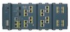
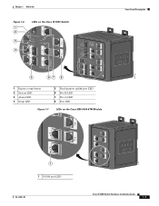
Chapter 1 Overview Figure 1-6 1 2 3 4 LEDs on the Cisco IE 3000 Switch Front-Panel Description 201703 5 67 8 1 Express setup button 2 System LED 3 Alarm LED 4 Setup LED 5 Dual-purpose uplink port LED 6 Pwr B LED 7 Pwr A LED 8 Port LED Figure 1-7 LEDs on the Cisco IEM-3000-8TM Module 201706 1 1 10/100 port LED OL-13017-01 Cisco IE 3000 Switch Hardware Installation Guide 1-7
Chapter 1 Overview Figure 1-6 1 2 3 4 LEDs on the Cisco IE 3000 Switch Front-Panel Description 201703 5 67 8 1 Express setup button 2 System LED 3 Alarm LED 4 Setup LED 5 Dual-purpose uplink port LED 6 Pwr B LED 7 Pwr A LED 8 Port LED Figure 1-7 LEDs on the Cisco IEM-3000-8TM Module 201706 1 1 10/100 port LED OL-13017-01 Cisco IE 3000 Switch Hardware Installation Guide 1-7

Installation Guide
Page 20
...affect connectivity, and errors such as shown in Figure 1-6, Figure 1-7, and Figure 1-8. Front-Panel Description Chapter 1 Overview Note The Pwr A and Pwr B LEDs show that power is present if the voltage at values near 18 V. The power status LEDs only show that the ...blocked by management, an address violation, or STP. Blinking green Activity. Activity. Solid green Link present. Link is disabled. 1-10 Cisco IE 3000 Switch Hardware Installation Guide OL-13017-01 Table 1-7 100BASE-FX MM Uplink Port Status LEDs Color Off Solid green Blinking green Blinking amber Alternating...
...affect connectivity, and errors such as shown in Figure 1-6, Figure 1-7, and Figure 1-8. Front-Panel Description Chapter 1 Overview Note The Pwr A and Pwr B LEDs show that power is present if the voltage at values near 18 V. The power status LEDs only show that the ...blocked by management, an address violation, or STP. Blinking green Activity. Activity. Solid green Link present. Link is disabled. 1-10 Cisco IE 3000 Switch Hardware Installation Guide OL-13017-01 Table 1-7 100BASE-FX MM Uplink Port Status LEDs Color Off Solid green Blinking green Blinking amber Alternating...
Installation Guide
Page 23
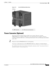
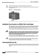
...-AC=) is mounted on page 2-44. OL-13017-01 Cisco IE 3000 Switch Hardware Installation Guide 1-13 The power converter (PWR-IE3000-AC) can supply 24-VDC power to one switch and up to the switch through a preassembled power cable. Chapter 1 Overview Figure 1-11 21 Cisco IE 3000 Switch Rear Panel Power Converter (Optional) 201697 1 DIN rail latch 2 Foot in recessed...
...-AC=) is mounted on page 2-44. OL-13017-01 Cisco IE 3000 Switch Hardware Installation Guide 1-13 The power converter (PWR-IE3000-AC) can supply 24-VDC power to one switch and up to the switch through a preassembled power cable. Chapter 1 Overview Figure 1-11 21 Cisco IE 3000 Switch Rear Panel Power Converter (Optional) 201697 1 DIN rail latch 2 Foot in recessed...
Installation Guide
Page 39
... kit. Never defeat the ground conductor or operate the equipment in the absence of the adapter cable to the Switch, page 2-21 Note The Cisco IE 3000 switch can get replacement power and relay connectors (PWR-IE3000-CNCT=) by using the ground screw, follow any grounding requirements at your site. Locate the power and relay connector...
... kit. Never defeat the ground conductor or operate the equipment in the absence of the adapter cable to the Switch, page 2-21 Note The Cisco IE 3000 switch can get replacement power and relay connectors (PWR-IE3000-CNCT=) by using the ground screw, follow any grounding requirements at your site. Locate the power and relay connector...

Installation Guide
Page 47
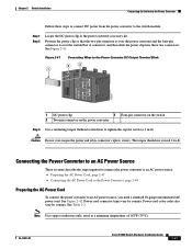
... relay connector so that they cannot be disturbed by casual contact. OL-13017-01 Cisco IE 3000 Switch Hardware Installation Guide 2-21 Figure 2-17 1 Connecting the Power and Relay Connector to the Switch 2 V RT A A V RT A A 201858 43 1 Power source A connector 2 Pwr A receptacle 3 Pwr B receptacle 4 Power source B connector Step 2 Use a racheting torque flathead screwdriver to tighten the captive...
... relay connector so that they cannot be disturbed by casual contact. OL-13017-01 Cisco IE 3000 Switch Hardware Installation Guide 2-21 Figure 2-17 1 Connecting the Power and Relay Connector to the Switch 2 V RT A A V RT A A 201858 43 1 Power source A connector 2 Pwr A receptacle 3 Pwr B receptacle 4 Power source B connector Step 2 Use a racheting torque flathead screwdriver to tighten the captive...
Installation Guide
Page 48
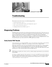
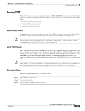
... page x. One at a time, the System, Alarm, Setup, Pwr A, and Pwr B LEDs each LED is ready to install the switch. 2-22 Cisco IE 3000 Switch Hardware Installation Guide OL-13017-01 Disconnect Power After successfully running POST, follow these steps. Verifying Switch Operation Chapter 2 Switch Installation Running POST When the switch powers on page 2-53. The POST runs a series of...
... page x. One at a time, the System, Alarm, Setup, Pwr A, and Pwr B LEDs each LED is ready to install the switch. 2-22 Cisco IE 3000 Switch Hardware Installation Guide OL-13017-01 Disconnect Power After successfully running POST, follow these steps. Verifying Switch Operation Chapter 2 Switch Installation Running POST When the switch powers on page 2-53. The POST runs a series of...

Installation Guide
Page 70
... DC Power Source, page 2-51 • Applying Power to the Power Converter, page 2-53 2-44 Cisco IE 3000 Switch Hardware Installation Guide OL-13017-01 This process takes about 30 seconds, and then the port LED turns ...Switch to the Switch, page 2-45 • Installing the Power Converter on a target device. See Chapter 3, "Troubleshooting," for loops. These sections describe the steps required to connect the switch to a power converter: • Attaching the Power Converter to the Power Converter The Cisco IE 3000 switch can be a problem with an optional AC/DC power converter (PWR...
... DC Power Source, page 2-51 • Applying Power to the Power Converter, page 2-53 2-44 Cisco IE 3000 Switch Hardware Installation Guide OL-13017-01 This process takes about 30 seconds, and then the port LED turns ...Switch to the Switch, page 2-45 • Installing the Power Converter on a target device. See Chapter 3, "Troubleshooting," for loops. These sections describe the steps required to connect the switch to a power converter: • Attaching the Power Converter to the Power Converter The Cisco IE 3000 switch can be a problem with an optional AC/DC power converter (PWR...
Installation Guide
Page 72
... Pwr A connector, you would a switch module. Warning This equipment is suitably designed for those specific environmental conditions that will be mounted within an enclosure that connects DC power from accessibility to live parts. Connecting the Switch to the Power Converter Chapter 2 Switch Installation Step 3 Step 4 Put the two modules together so that connector. 2-46 Cisco IE 3000 Switch...
... Pwr A connector, you would a switch module. Warning This equipment is suitably designed for those specific environmental conditions that will be mounted within an enclosure that connects DC power from accessibility to live parts. Connecting the Switch to the Power Converter Chapter 2 Switch Installation Step 3 Step 4 Put the two modules together so that connector. 2-46 Cisco IE 3000 Switch...
Installation Guide
Page 73
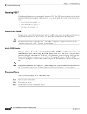
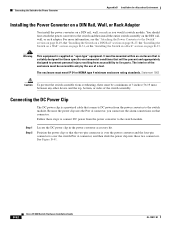
... Power Converter DC Output Terminal Block 2 3 5 1 6 2 7 1 3 8 2 4 CONSOLE 202298 1 DC power clip 3 Four-pin connector on the switch 2 Two-pin connector on the power convertor Step 3 Use a ratcheting torque flathead screwdriver to tighten the captive screw to an AC power source, you need... over the switch Pwr A connector, and then slide the power clip into these steps to connect DC power from the power converter to the switch module. OL-13017-01 Cisco IE 3000 Switch Hardware Installation Guide 2-47 See Figure 2-41. Chapter 2 Switch Installation Connecting the Switch to the ...
... Power Converter DC Output Terminal Block 2 3 5 1 6 2 7 1 3 8 2 4 CONSOLE 202298 1 DC power clip 3 Four-pin connector on the switch 2 Two-pin connector on the power convertor Step 3 Use a ratcheting torque flathead screwdriver to tighten the captive screw to an AC power source, you need... over the switch Pwr A connector, and then slide the power clip into these steps to connect DC power from the power converter to the switch module. OL-13017-01 Cisco IE 3000 Switch Hardware Installation Guide 2-47 See Figure 2-41. Chapter 2 Switch Installation Connecting the Switch to the ...
Installation Guide
Page 81
...for details. OL-13017-01 Cisco IE 3000 Switch Hardware Installation Guide 3-1 POST starts with LED tests that came with your switch does not pass POST. If the switch fails POST, the System LED turns red. For more information about the switch. You can also view ... port-connectivity problems, and overall switch performance. See the switch software configuration guide, the switch command reference, or the documentation that cycles once through the System, Alarm, Setup, Pwr A, and Pwr B LEDs. If you might take several minutes for the switch to solid green, and the ...
...for details. OL-13017-01 Cisco IE 3000 Switch Hardware Installation Guide 3-1 POST starts with LED tests that came with your switch does not pass POST. If the switch fails POST, the System LED turns red. For more information about the switch. You can also view ... port-connectivity problems, and overall switch performance. See the switch software configuration guide, the switch command reference, or the documentation that cycles once through the System, Alarm, Setup, Pwr A, and Pwr B LEDs. If you might take several minutes for the switch to solid green, and the ...

Installation Guide
Page 106
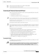
...-AC). For instructions on how to connect the power converter to the switch, see the "Connecting the Switch to the Switch, page B-24 Note The Cisco IE 3000 switch can get replacement power and relay connectors (PWR-IE3000-CNCT=) by calling Cisco Technical Support. Connecting the Protective Ground and DC Power These sections describe the steps required to connect...
...-AC). For instructions on how to connect the power converter to the switch, see the "Connecting the Switch to the Switch, page B-24 Note The Cisco IE 3000 switch can get replacement power and relay connectors (PWR-IE3000-CNCT=) by calling Cisco Technical Support. Connecting the Protective Ground and DC Power These sections describe the steps required to connect...

Installation Guide
Page 114
... panel. When you are installing the switch and are testing the switch, one power source is accidentally removed. B-24 Cisco IE 3000 Switch Hardware Installation Guide OL-13017-01 Statement 1058 Figure B-17 1 Connecting the Power and Relay Connector to the Switch 2 V RT A A V RT A A 201858 43 1 Power source A connector 2 Pwr A receptacle 3 Pwr B receptacle 4 Power source B connector Step 2 Use a ratcheting...
... panel. When you are installing the switch and are testing the switch, one power source is accidentally removed. B-24 Cisco IE 3000 Switch Hardware Installation Guide OL-13017-01 Statement 1058 Figure B-17 1 Connecting the Power and Relay Connector to the Switch 2 V RT A A V RT A A 201858 43 1 Power source A connector 2 Pwr A receptacle 3 Pwr B receptacle 4 Power source B connector Step 2 Use a ratcheting...
Installation Guide
Page 115
... ON position. One at a time, the System, Alarm, Setup, Pwr A, and Pwr B LEDs each LED is tested. See the "Obtaining Documentation, Obtaining Support, and Security Guidelines" section on page B-59. Decide where you power on the switch, it automatically initiates a POST. OL-13017-01 Cisco IE 3000 Switch Hardware Installation Guide B-25 Disconnect Power After successfully running...
... ON position. One at a time, the System, Alarm, Setup, Pwr A, and Pwr B LEDs each LED is tested. See the "Obtaining Documentation, Obtaining Support, and Security Guidelines" section on page B-59. Decide where you power on the switch, it automatically initiates a POST. OL-13017-01 Cisco IE 3000 Switch Hardware Installation Guide B-25 Disconnect Power After successfully running...

Installation Guide
Page 139
... arc can be a problem with an optional AC/DC power converter (PWR-IE3000-AC). Statement 1081 OL-13017-01 Cisco IE 3000 Switch Hardware Installation Guide B-49 Connecting the Switch to the Power Converter The Cisco IE 3000 switch can occur. These sections describe the steps required to connect the switch to a power converter: • Attaching the Power Converter to the...
... arc can be a problem with an optional AC/DC power converter (PWR-IE3000-AC). Statement 1081 OL-13017-01 Cisco IE 3000 Switch Hardware Installation Guide B-49 Connecting the Switch to the Power Converter The Cisco IE 3000 switch can occur. These sections describe the steps required to connect the switch to a power converter: • Attaching the Power Converter to the...
Installation Guide
Page 141
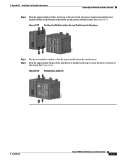
... the lower module latches up to secure the power converter to the switch. Push the upper module latches down . WARNING Tpeploohewwicseetrurrinccciotosrmrhddois.gchbkTteohfdoairrsveecedosumnecnroevericecthtintehtghareunisnkotitwn.oeof Pwr B (24VDC or 48 VDC) 1 Rtn B 6 Minor Alarm 2 Express Setup System Pwr A Alarm Pwr B 7 Setup 1 3 8 2 4 Cisco Catalyst OL-13017-01 Cisco IE 3000 Switch Hardware Installation Guide B-51 See Figure B-40. See Figure B-39. Figure B-39...
... the lower module latches up to secure the power converter to the switch. Push the upper module latches down . WARNING Tpeploohewwicseetrurrinccciotosrmrhddois.gchbkTteohfdoairrsveecedosumnecnroevericecthtintehtghareunisnkotitwn.oeof Pwr B (24VDC or 48 VDC) 1 Rtn B 6 Minor Alarm 2 Express Setup System Pwr A Alarm Pwr B 7 Setup 1 3 8 2 4 Cisco Catalyst OL-13017-01 Cisco IE 3000 Switch Hardware Installation Guide B-51 See Figure B-40. See Figure B-39. Figure B-39...
Installation Guide
Page 142
... mm) between any other device and the top, bottom, or sides of the switch assembly. See Figure B-41. B-52 Cisco IE 3000 Switch Hardware Installation Guide OL-13017-01 Warning This equipment is over the switch Pwr A connector, and then slide the power clip into these steps to connect DC ...power from the power converter to the switch and then install the entire switch assembly on that will...
... mm) between any other device and the top, bottom, or sides of the switch assembly. See Figure B-41. B-52 Cisco IE 3000 Switch Hardware Installation Guide OL-13017-01 Warning This equipment is over the switch Pwr A connector, and then slide the power clip into these steps to connect DC ...power from the power converter to the switch and then install the entire switch assembly on that will...