
Installation Guide
Page 3
... 1-8 System LED 1-9 Alarm LED 1-9 Power Status LED 1-9 10/100 Port Status LEDs 1-10 100Base-FX Port Status LEDs 1-10 Dual-Purpose Port LEDs 1-11 Compact Flash Memory Card 1-11 Rear-Panel Description 1-12 Power Converter (Optional) 1-13 Management Options 1-14 Network Configurations 1-15 Switch Installation 2-1 Preparing for Installation 2-1 Warnings 2-2 Cisco IE 3000 Switch Hardware Installation Guide iii
... 1-8 System LED 1-9 Alarm LED 1-9 Power Status LED 1-9 10/100 Port Status LEDs 1-10 100Base-FX Port Status LEDs 1-10 Dual-Purpose Port LEDs 1-11 Compact Flash Memory Card 1-11 Rear-Panel Description 1-12 Power Converter (Optional) 1-13 Management Options 1-14 Network Configurations 1-15 Switch Installation 2-1 Preparing for Installation 2-1 Warnings 2-2 Cisco IE 3000 Switch Hardware Installation Guide iii

Installation Guide
Page 4
... 2-42 Connecting to 100BASE-FX Ports 2-43 Connecting the Switch to the Power Converter 2-44 Attaching the Power Converter to the Switch 2-45 Installing the Power Converter on a DIN Rail, Wall, or Rack Adapter 2-46 Connecting the DC Power Clip 2-46 Connecting the Power Converter to an AC Power Source 2-47 Cisco IE 3000 Switch Hardware Installation Guide iv OL-13017-01
... 2-42 Connecting to 100BASE-FX Ports 2-43 Connecting the Switch to the Power Converter 2-44 Attaching the Power Converter to the Switch 2-45 Installing the Power Converter on a DIN Rail, Wall, or Rack Adapter 2-46 Connecting the DC Power Clip 2-46 Connecting the Power Converter to an AC Power Source 2-47 Cisco IE 3000 Switch Hardware Installation Guide iv OL-13017-01

Installation Guide
Page 5
... to Recover Passwords 3-5 Finding the Switch Serial Number 3-6 Technical Specifications A-1 Installation In a Hazardous Environment B-1 Preparing for Installation B-1 Warnings B-2 North American Hazardous Location Approval B-5 EMC Environmental Conditions for Products Installed in the European Union B-5 Installation Guidelines B-5 Environment and Enclosure Guidelines: B-5 Other Guidelines B-6 Verifying Package Contents B-7 Adding Modules to the Switch B-8 Cisco IE 3000 Switch Hardware Installation Guide v
... to Recover Passwords 3-5 Finding the Switch Serial Number 3-6 Technical Specifications A-1 Installation In a Hazardous Environment B-1 Preparing for Installation B-1 Warnings B-2 North American Hazardous Location Approval B-5 EMC Environmental Conditions for Products Installed in the European Union B-5 Installation Guidelines B-5 Environment and Enclosure Guidelines: B-5 Other Guidelines B-6 Verifying Package Contents B-7 Adding Modules to the Switch B-8 Cisco IE 3000 Switch Hardware Installation Guide v
Installation Guide
Page 6
..., Wall, or Rack Adapter B-52 Connecting the DC Power Clip B-52 Connecting the Power Converter to an AC Power Source B-53 Preparing the AC Power Cord B-53 Connecting the AC Power Cord to the Power Converter B-54 Connecting the Power Converter to a DC Power Source B-57 Applying Power to the Power Converter B-59 Cisco IE 3000 Switch Hardware Installation Guide vi OL-13017-01
..., Wall, or Rack Adapter B-52 Connecting the DC Power Clip B-52 Connecting the Power Converter to an AC Power Source B-53 Preparing the AC Power Cord B-53 Connecting the AC Power Cord to the Power Converter B-54 Connecting the Power Converter to a DC Power Source B-57 Applying Power to the Power Converter B-59 Cisco IE 3000 Switch Hardware Installation Guide vi OL-13017-01
Installation Guide
Page 11
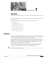
... 1-2 • Compact Flash Memory Card, page 1-11 • Rear-Panel Description, page 1-12 • Power Converter (Optional), page 1-13 • Management Options, page 1-14 • Network Configurations, page 1-15 Overview The Cisco IE 3000 switch provides a rugged and secure switching infrastructure for industrial Ethernet applications, including factory automation, intelligent transportation systems (ITSs), substations, and other deployments in a standard...
... 1-2 • Compact Flash Memory Card, page 1-11 • Rear-Panel Description, page 1-12 • Power Converter (Optional), page 1-13 • Management Options, page 1-14 • Network Configurations, page 1-15 Overview The Cisco IE 3000 switch provides a rugged and secure switching infrastructure for industrial Ethernet applications, including factory automation, intelligent transportation systems (ITSs), substations, and other deployments in a standard...

Installation Guide
Page 12
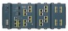
... the switch, see the "Adding Modules to Figure 1-4 show the switch and expansion module front panels. For instructions on page 2-5. . Table 1-1 Cisco IE 3000 Switch Models Switch Model Cisco IE-3000-4TC Cisco IE-3000-8TC Cisco IEM-3000-8TM Cisco IEM-3000-8FM Description 4 10/100BASE-T Ethernet ports ...The switch front panel contains the ports, the LEDs, and the power and relay connectors. Cisco IE 3000 Switch Hardware Installation Guide 1-2 OL-13017-01 The Cisco IE-3000-4TC and the Cisco IE-3000-8TC are the switch models, and the Cisco IEM-3000-8TM and the Cisco IEM-3000-8FM ...
... the switch, see the "Adding Modules to Figure 1-4 show the switch and expansion module front panels. For instructions on page 2-5. . Table 1-1 Cisco IE 3000 Switch Models Switch Model Cisco IE-3000-4TC Cisco IE-3000-8TC Cisco IEM-3000-8TM Cisco IEM-3000-8FM Description 4 10/100BASE-T Ethernet ports ...The switch front panel contains the ports, the LEDs, and the power and relay connectors. Cisco IE 3000 Switch Hardware Installation Guide 1-2 OL-13017-01 The Cisco IE-3000-4TC and the Cisco IE-3000-8TC are the switch models, and the Cisco IEM-3000-8TM and the Cisco IEM-3000-8FM ...

Installation Guide
Page 13
Chapter 1 Overview Figure 1-1 Cisco IE-3000-8TC Switch 1 2 Front-Panel Description 201699 3 45 1 Power and relay connectors 4 10/100 ports 2 Console port 5 Protective ground connection 3 Dual-purpose ports Figure 1-2 Cisco IE-3000-4TC Switch 1 2 201700 3 45 1 Power and relay connectors 4 2 Console port 5 3 Dual-purpose ports 10/100 ports Protective ground connection OL-13017-01 Cisco IE 3000 Switch Hardware Installation Guide 1-3
Chapter 1 Overview Figure 1-1 Cisco IE-3000-8TC Switch 1 2 Front-Panel Description 201699 3 45 1 Power and relay connectors 4 10/100 ports 2 Console port 5 Protective ground connection 3 Dual-purpose ports Figure 1-2 Cisco IE-3000-4TC Switch 1 2 201700 3 45 1 Power and relay connectors 4 2 Console port 5 3 Dual-purpose ports 10/100 ports Protective ground connection OL-13017-01 Cisco IE 3000 Switch Hardware Installation Guide 1-3

Installation Guide
Page 15
...Overview Front-Panel Description 10/100 Ports You can set these SFP modules, see the switch software configuration guide or the switch command reference. Power and Relay Connector You connect the DC power and alarm signals to enable the automatic medium-dependent interface crossover (auto-MDIX) feature...more information.) You can use Gigabit Ethernet SFP modules to establish fiber-optic connections to operate at 10 or 100 Mb/s in an SFP module slot. You can also set the 10/100 ports to other switches. OL-13017-01 Cisco IE 3000 Switch Hardware Installation Guide 1-5 You can...
...Overview Front-Panel Description 10/100 Ports You can set these SFP modules, see the switch software configuration guide or the switch command reference. Power and Relay Connector You connect the DC power and alarm signals to enable the automatic medium-dependent interface crossover (auto-MDIX) feature...more information.) You can use Gigabit Ethernet SFP modules to establish fiber-optic connections to operate at 10 or 100 Mb/s in an SFP module slot. You can also set the 10/100 ports to other switches. OL-13017-01 Cisco IE 3000 Switch Hardware Installation Guide 1-5 You can...

Installation Guide
Page 16
...45-to-DB-9 adapter cable. LEDs You can associate any alarm condition with one of the two power sources fail, the other continues to indicate an alarm with dual power sources. Cisco IE 3000 Switch Hardware Installation Guide 1-6 OL-13017-01 When both alarm relays. From the CLI, you can order... a kit (part number ACS-DSBUASYN=) with that adapter from the DC source with both power sources are labeled A, and you can...
...45-to-DB-9 adapter cable. LEDs You can associate any alarm condition with one of the two power sources fail, the other continues to indicate an alarm with dual power sources. Cisco IE 3000 Switch Hardware Installation Guide 1-6 OL-13017-01 When both alarm relays. From the CLI, you can order... a kit (part number ACS-DSBUASYN=) with that adapter from the DC source with both power sources are labeled A, and you can...

Installation Guide
Page 19
... Off Alarms are not configured, or the switch is not present; If alarms are configured. OL-13017-01 Cisco IE 3000 Switch Hardware Installation Guide 1-9 Red Switch has detected a minor alarm. otherwise, the LED is operating normally. Alarm LED Table 1-4 lists the alarm LED colors and their meanings. If power is present on the circuit, or the...
... Off Alarms are not configured, or the switch is not present; If alarms are configured. OL-13017-01 Cisco IE 3000 Switch Hardware Installation Guide 1-9 Red Switch has detected a minor alarm. otherwise, the LED is operating normally. Alarm LED Table 1-4 lists the alarm LED colors and their meanings. If power is present on the circuit, or the...

Installation Guide
Page 20
... individual ports. Blinking green Activity. Activity. Link is disabled. 1-10 Cisco IE 3000 Switch Hardware Installation Guide OL-13017-01 The difference, or hysteresis, ensures that the power status LEDs do not oscillate at the switch input exceeds the valid level. Error frames can remain amber for up ... receiving data. Link is sending or receiving data. For information about the power LED colors during the power-on self-test (POST), see the "Verifying Switch Operation" section on the switch if the power input drops below the low valid level. Solid amber Port is sending or...
... individual ports. Blinking green Activity. Activity. Link is disabled. 1-10 Cisco IE 3000 Switch Hardware Installation Guide OL-13017-01 The difference, or hysteresis, ensures that the power status LEDs do not oscillate at the switch input exceeds the valid level. Error frames can remain amber for up ... receiving data. Link is sending or receiving data. For information about the power LED colors during the power-on self-test (POST), see the "Verifying Switch Operation" section on the switch if the power input drops below the low valid level. Solid amber Port is sending or...
Installation Guide
Page 22
... Description Figure 1-10 Compact Flash Memory Card Slot Chapter 1 Overview 201832 Bottom 1 of the switch, modules, and power converter have latches for installation on the wall. 1-12 Cisco IE 3000 Switch Hardware Installation Guide OL-13017-01 Rear-Panel Description The rear panel of switch Note You can obtain replacement flash memory cards (CF-IE3000=) by calling...
... Description Figure 1-10 Compact Flash Memory Card Slot Chapter 1 Overview 201832 Bottom 1 of the switch, modules, and power converter have latches for installation on the wall. 1-12 Cisco IE 3000 Switch Hardware Installation Guide OL-13017-01 Rear-Panel Description The rear panel of switch Note You can obtain replacement flash memory cards (CF-IE3000=) by calling...
Installation Guide
Page 23
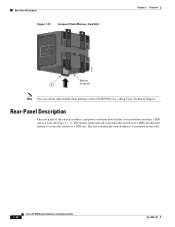
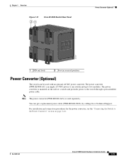
... 21 Cisco IE 3000 Switch Rear Panel Power Converter (Optional) 201697 1 DIN rail latch 2 Foot in recessed position Power Converter (Optional) The switch can get a replacement power cable (PWR-IE3000-CLP=) by calling Cisco Technical Support. The power converter (PWR-IE3000-AC) can supply 24-VDC power to one switch and up to the switch through a preassembled power cable. OL-13017-01 Cisco IE 3000 Switch Hardware Installation...
... 21 Cisco IE 3000 Switch Rear Panel Power Converter (Optional) 201697 1 DIN rail latch 2 Foot in recessed position Power Converter (Optional) The switch can get a replacement power cable (PWR-IE3000-CLP=) by calling Cisco Technical Support. The power converter (PWR-IE3000-AC) can supply 24-VDC power to one switch and up to the switch through a preassembled power cable. OL-13017-01 Cisco IE 3000 Switch Hardware Installation...
Installation Guide
Page 24
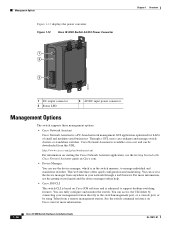
... web interface offers quick configuration and monitoring. Figure 1-12 Cisco IE 3000 Switch AC/DC Power Converter 1 2 3 Chapter 1 Overview 202314 1 DC output connector 2 Status LED 3 AC/DC input power connector Management Options The switch supports these management options: • Cisco Network Assistant Cisco Network Assistant is enhanced to support desktop-switching features. Through a GUI, users can access the CLI either...
... web interface offers quick configuration and monitoring. Figure 1-12 Cisco IE 3000 Switch AC/DC Power Converter 1 2 3 Chapter 1 Overview 202314 1 DC output connector 2 Status LED 3 AC/DC input power connector Management Options The switch supports these management options: • Cisco Network Assistant Cisco Network Assistant is enhanced to support desktop-switching features. Through a GUI, users can access the CLI either...
Installation Guide
Page 27
...topics: • Warnings, page 2-2 • Installation Guidelines, page 2-3 • Verifying Package Contents, page 2-5 OL-13017-01 Cisco IE 3000 Switch Hardware Installation Guide 2-1 Switch Installation 2 C H A P T E R This chapter describes how to install your installation is in a hazardous environment, see... page 2-1 • Adding Modules to the Switch, page 2-5 • Installing or Removing the Compact Flash Memory Card, page 2-10 • Verifying Switch Operation, page 2-11 • Installing the Switch, page 2-23 • Connecting Power and Alarm Circuits, page 2-32 • ...
...topics: • Warnings, page 2-2 • Installation Guidelines, page 2-3 • Verifying Package Contents, page 2-5 OL-13017-01 Cisco IE 3000 Switch Hardware Installation Guide 2-1 Switch Installation 2 C H A P T E R This chapter describes how to install your installation is in a hazardous environment, see... page 2-1 • Adding Modules to the Switch, page 2-5 • Installing or Removing the Compact Flash Memory Card, page 2-10 • Verifying Switch Operation, page 2-11 • Installing the Switch, page 2-23 • Connecting Power and Alarm Circuits, page 2-32 • ...
Installation Guide
Page 28
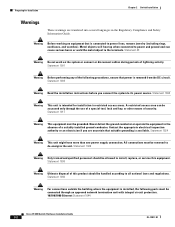
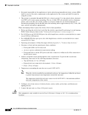
...of the following ports must be accessed only through an approved network termination unit with integral circuit protection. 10/100/1000 Ethernet Statement 1044 Cisco IE 3000 Switch Hardware Installation Guide 2-2 OL-13017-01 Never defeat the ground conductor or operate the equipment in the absence of lightning ... inspection authority or an electrician if you connect the system to all national laws and regulations. All connections must be removed to power and ground and can be connected through the use of a special tool, lock and key, or other means of this equipment...
...of the following ports must be accessed only through an approved network termination unit with integral circuit protection. 10/100/1000 Ethernet Statement 1044 Cisco IE 3000 Switch Hardware Installation Guide 2-2 OL-13017-01 Never defeat the ground conductor or operate the equipment in the absence of lightning ... inspection authority or an electrician if you connect the system to all national laws and regulations. All connections must be removed to power and ground and can be connected through the use of a special tool, lock and key, or other means of this equipment...
Installation Guide
Page 30
...• Clearance to chassis ground. Note When the switch is installed in an industrial enclosure, the temperature within reach of the connection to place the switch, observe these conditions: - Preparing for Installation Chapter 2 Switch Installation • Personnel responsible for the application of ... Front-panel direct current (DC) power and relay connector is within the enclosure is operational by powering it on ) that can corrode, oxidize, or are poor conductors can be the following minimum clearances: - Cisco IE 3000 Switch Hardware Installation Guide 2-4 OL-13017-...
...• Clearance to chassis ground. Note When the switch is installed in an industrial enclosure, the temperature within reach of the connection to place the switch, observe these conditions: - Preparing for Installation Chapter 2 Switch Installation • Personnel responsible for the application of ... Front-panel direct current (DC) power and relay connector is within the enclosure is operational by powering it on ) that can corrode, oxidize, or are poor conductors can be the following minimum clearances: - Cisco IE 3000 Switch Hardware Installation Guide 2-4 OL-13017-...
Installation Guide
Page 31
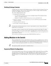
...Cisco IEM-3000-8TM or a Cisco IEM-3000-8FM. You cannot add two Cisco IEM-3000-8FM expansion modules. Chapter 2 Switch Installation Adding Modules to the Switch The Cisco IE-3000-4TC or the Cisco IE-3000-8TC switch can operate as standalone devices with four or eight Fast Ethernet ports, respectively. Adding Modules to the Switch...25 female DTE adapter. Cisco IE 3000 Switch Getting Started Guide (in German) • Two power and relay connectors • RJ-45 to the shipping container and save them. You can be either a Cisco IEM-3000-8TM or a Cisco IEM-3000-8FM. Return all packing...
...Cisco IEM-3000-8TM or a Cisco IEM-3000-8FM. You cannot add two Cisco IEM-3000-8FM expansion modules. Chapter 2 Switch Installation Adding Modules to the Switch The Cisco IE-3000-4TC or the Cisco IE-3000-8TC switch can operate as standalone devices with four or eight Fast Ethernet ports, respectively. Adding Modules to the Switch...25 female DTE adapter. Cisco IE 3000 Switch Getting Started Guide (in German) • Two power and relay connectors • RJ-45 to the shipping container and save them. You can be either a Cisco IEM-3000-8TM or a Cisco IEM-3000-8FM. Return all packing...
Installation Guide
Page 37
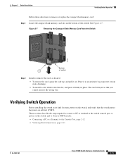
..., page 2-12 • Verifying Switch Operation, page 2-11 OL-13017-01 Cisco IE 3000 Switch Hardware Installation Guide 2-11 These sections describe the steps required to connect a PC or terminal to the switch console port, to power on self-test (POST). Verifying Switch Operation Before installing the switch in place. See Figure 2-7. Chapter 2 Switch Installation Verifying Switch Operation Follow these directions...
..., page 2-12 • Verifying Switch Operation, page 2-11 OL-13017-01 Cisco IE 3000 Switch Hardware Installation Guide 2-11 These sections describe the steps required to connect a PC or terminal to the switch console port, to power on self-test (POST). Verifying Switch Operation Before installing the switch in place. See Figure 2-7. Chapter 2 Switch Installation Verifying Switch Operation Follow these directions...
Installation Guide
Page 39
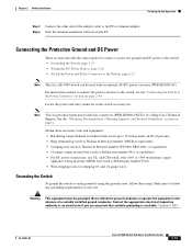
... Statement 1024 OL-13017-01 Cisco IE 3000 Switch Hardware Installation Guide 2-13 and CSA-rated, style 1007 or 1569 twisted-pair copper appliance wiring material (AWM) wire (such as Belden part number 9912 or equivalent) • For DC power connections, use UL- For instructions...must be used with an optional AC/DC power converter (PWR-IE3000-AC). Chapter 2 Switch Installation Verifying Switch Operation Step 5 Connect the other end of the adapter cable to the Switch, page 2-21 Note The Cisco IE 3000 switch can get replacement power and relay connectors (PWR-IE3000-CNCT=) ...
... Statement 1024 OL-13017-01 Cisco IE 3000 Switch Hardware Installation Guide 2-13 and CSA-rated, style 1007 or 1569 twisted-pair copper appliance wiring material (AWM) wire (such as Belden part number 9912 or equivalent) • For DC power connections, use UL- For instructions...must be used with an optional AC/DC power converter (PWR-IE3000-AC). Chapter 2 Switch Installation Verifying Switch Operation Step 5 Connect the other end of the adapter cable to the Switch, page 2-21 Note The Cisco IE 3000 switch can get replacement power and relay connectors (PWR-IE3000-CNCT=) ...
