
Installation Guide
Page 3
... LED 1-8 System LED 1-9 Alarm LED 1-9 Power Status LED 1-9 10/100 Port Status LEDs 1-10 100Base-FX Port Status LEDs 1-10 Dual-Purpose Port LEDs 1-11 Compact Flash Memory Card 1-11 Rear-Panel Description 1-12 Power Converter (Optional) 1-13 Management Options 1-14 Network Configurations 1-15 Switch Installation 2-1 Preparing for Installation 2-1 Warnings 2-2 Cisco IE 3000 Switch Hardware Installation Guide iii
... LED 1-8 System LED 1-9 Alarm LED 1-9 Power Status LED 1-9 10/100 Port Status LEDs 1-10 100Base-FX Port Status LEDs 1-10 Dual-Purpose Port LEDs 1-11 Compact Flash Memory Card 1-11 Rear-Panel Description 1-12 Power Converter (Optional) 1-13 Management Options 1-14 Network Configurations 1-15 Switch Installation 2-1 Preparing for Installation 2-1 Warnings 2-2 Cisco IE 3000 Switch Hardware Installation Guide iii

Installation Guide
Page 4
...2-5 Adding Modules to the Switch 2-5 Expansion Module Configurations 2-5 Connecting Modules 2-8 Installing or Removing the Compact Flash Memory Card 2-10 Verifying Switch Operation 2-11 Connecting a PC or a Terminal to the Console Port 2-12 Connecting the Protective ...Port 2-42 Connecting to 100BASE-FX Ports 2-43 Connecting the Switch to the Power Converter 2-44 Attaching the Power Converter to the Switch 2-45 Installing the Power Converter on a DIN Rail, Wall, or Rack Adapter 2-46 Connecting the DC Power Clip 2-46 Connecting the Power Converter to an AC Power Source 2-47 Cisco IE 3000 Switch...
...2-5 Adding Modules to the Switch 2-5 Expansion Module Configurations 2-5 Connecting Modules 2-8 Installing or Removing the Compact Flash Memory Card 2-10 Verifying Switch Operation 2-11 Connecting a PC or a Terminal to the Console Port 2-12 Connecting the Protective ...Port 2-42 Connecting to 100BASE-FX Ports 2-43 Connecting the Switch to the Power Converter 2-44 Attaching the Power Converter to the Switch 2-45 Installing the Power Converter on a DIN Rail, Wall, or Rack Adapter 2-46 Connecting the DC Power Clip 2-46 Connecting the Power Converter to an AC Power Source 2-47 Cisco IE 3000 Switch...

Installation Guide
Page 5
... to Recover Passwords 3-5 Finding the Switch Serial Number 3-6 Technical Specifications A-1 Installation In a Hazardous Environment B-1 Preparing for Installation B-1 Warnings B-2 North American Hazardous Location Approval B-5 EMC Environmental Conditions for Products Installed in the European Union B-5 Installation Guidelines B-5 Environment and Enclosure Guidelines: B-5 Other Guidelines B-6 Verifying Package Contents B-7 Adding Modules to the Switch B-8 Cisco IE 3000 Switch Hardware Installation Guide v
... to Recover Passwords 3-5 Finding the Switch Serial Number 3-6 Technical Specifications A-1 Installation In a Hazardous Environment B-1 Preparing for Installation B-1 Warnings B-2 North American Hazardous Location Approval B-5 EMC Environmental Conditions for Products Installed in the European Union B-5 Installation Guidelines B-5 Environment and Enclosure Guidelines: B-5 Other Guidelines B-6 Verifying Package Contents B-7 Adding Modules to the Switch B-8 Cisco IE 3000 Switch Hardware Installation Guide v
Installation Guide
Page 6
... SFP Modules from SFP Module Slots B-44 Connecting to SFP Modules B-45 Connecting to a Dual-Purpose Port B-46 Connecting to 100BASE-FX Ports B-48 Connecting the Switch to the Power Converter B-49 Attaching the Power Converter to the Switch B-49 Installing the Power Converter on a DIN Rail, Wall, or Rack Adapter B-52 Connecting the... the AC Power Cord to the Power Converter B-54 Connecting the Power Converter to a DC Power Source B-57 Applying Power to the Power Converter B-59 Cisco IE 3000 Switch Hardware Installation Guide vi OL-13017-01
... SFP Modules from SFP Module Slots B-44 Connecting to SFP Modules B-45 Connecting to a Dual-Purpose Port B-46 Connecting to 100BASE-FX Ports B-48 Connecting the Switch to the Power Converter B-49 Attaching the Power Converter to the Switch B-49 Installing the Power Converter on a DIN Rail, Wall, or Rack Adapter B-52 Connecting the... the AC Power Cord to the Power Converter B-54 Connecting the Power Converter to a DC Power Source B-57 Applying Power to the Power Converter B-59 Cisco IE 3000 Switch Hardware Installation Guide vi OL-13017-01
Installation Guide
Page 7
... a Crossover Cable C-7 Four Twisted-Pair Cable Pinouts for 1000BASE-T Ports C-7 Adapter Pinouts C-8 Configuring the Switch with the CLI-Based Setup Program D-1 Accessing the CLI from the Console Port D-1 Entering the Initial Configuration Information D-2 IP Settings D-2 Completing the Setup Program D-2 Contents OL-13017-01 Cisco IE 3000 Switch Hardware Installation Guide vii and 100BASE-TX-Compatible Devices C-1 Connecting...
... a Crossover Cable C-7 Four Twisted-Pair Cable Pinouts for 1000BASE-T Ports C-7 Adapter Pinouts C-8 Configuring the Switch with the CLI-Based Setup Program D-1 Accessing the CLI from the Console Port D-1 Entering the Initial Configuration Information D-2 IP Settings D-2 Completing the Setup Program D-2 Contents OL-13017-01 Cisco IE 3000 Switch Hardware Installation Guide vii and 100BASE-TX-Compatible Devices C-1 Connecting...

Installation Guide
Page 12
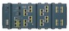
Table 1-1 Cisco IE 3000 Switch Models Switch Model Cisco IE-3000-4TC Cisco IE-3000-8TC Cisco IEM-3000-8TM Cisco IEM-3000-8FM Description 4 10/100BASE-T Ethernet ports and 2 dual-purpose ports, each with a 10/100/1000BASE-T copper port and an SFP (small form-factor pluggable) module slot 8 10/100BASE-T Ethernet ports and 2 dual-purpose ports Expansion module with 8 10/100BASE-T copper Ethernet ports Expansion module with 8 100BASE-FX fiber-optic Ethernet ports Front-Panel Description This...
Table 1-1 Cisco IE 3000 Switch Models Switch Model Cisco IE-3000-4TC Cisco IE-3000-8TC Cisco IEM-3000-8TM Cisco IEM-3000-8FM Description 4 10/100BASE-T Ethernet ports and 2 dual-purpose ports, each with a 10/100/1000BASE-T copper port and an SFP (small form-factor pluggable) module slot 8 10/100BASE-T Ethernet ports and 2 dual-purpose ports Expansion module with 8 10/100BASE-T copper Ethernet ports Expansion module with 8 100BASE-FX fiber-optic Ethernet ports Front-Panel Description This...

Installation Guide
Page 13
Chapter 1 Overview Figure 1-1 Cisco IE-3000-8TC Switch 1 2 Front-Panel Description 201699 3 45 1 Power and relay connectors 4 10/100 ports 2 Console port 5 Protective ground connection 3 Dual-purpose ports Figure 1-2 Cisco IE-3000-4TC Switch 1 2 201700 3 45 1 Power and relay connectors 4 2 Console port 5 3 Dual-purpose ports 10/100 ports Protective ground connection OL-13017-01 Cisco IE 3000 Switch Hardware Installation Guide 1-3
Chapter 1 Overview Figure 1-1 Cisco IE-3000-8TC Switch 1 2 Front-Panel Description 201699 3 45 1 Power and relay connectors 4 10/100 ports 2 Console port 5 Protective ground connection 3 Dual-purpose ports Figure 1-2 Cisco IE-3000-4TC Switch 1 2 201700 3 45 1 Power and relay connectors 4 2 Console port 5 3 Dual-purpose ports 10/100 ports Protective ground connection OL-13017-01 Cisco IE 3000 Switch Hardware Installation Guide 1-3

Installation Guide
Page 15
...provides secondary power and the minor alarm signal. OL-13017-01 Cisco IE 3000 Switch Hardware Installation Guide 1-5 In all cases, the attached device must be active at a time. You can configure them as an SFP module port. These ports use Category 3 or Category 4 cables. Power and Relay Connector ... or 1000 Mb/s (Gigabit) Ethernet ports and can use a small-form-factor fixed (SFF) fiber-optic transceiver module that is enabled, the switch detects the required cable type for your switch software. 100BASE-FX Ports The IEEE 802.3u 100BASE-FX ports provide full-duplex 100 Mb/s ...
...provides secondary power and the minor alarm signal. OL-13017-01 Cisco IE 3000 Switch Hardware Installation Guide 1-5 In all cases, the attached device must be active at a time. You can configure them as an SFP module port. These ports use Category 3 or Category 4 cables. Power and Relay Connector ... or 1000 Mb/s (Gigabit) Ethernet ports and can use a small-form-factor fixed (SFF) fiber-optic transceiver module that is enabled, the switch detects the required cable type for your switch software. 100BASE-FX Ports The IEEE 802.3u 100BASE-FX ports provide full-duplex 100 Mb/s ...

Installation Guide
Page 16
...RJ-45-to monitor individual switches and switch clusters. Both alarm terminals on the power and relay connector are operational, the switch draws power from the DC source with that adapter from Cisco Systems. For console-port and adapter-pinout information, see... Appendix C, "Cable and Connectors." See the switch software configuration guide for terminating the DC power and alarm wire and the connector plugs into the power and relay receptacles on page C-5. You can use the CLI to configure and to -DB-25 female DTE adapter. Cisco IE 3000 Switch...
...RJ-45-to monitor individual switches and switch clusters. Both alarm terminals on the power and relay connector are operational, the switch draws power from the DC source with that adapter from Cisco Systems. For console-port and adapter-pinout information, see... Appendix C, "Cable and Connectors." See the switch software configuration guide for terminating the DC power and alarm wire and the connector plugs into the power and relay receptacles on page C-5. You can use the CLI to configure and to -DB-25 female DTE adapter. Cisco IE 3000 Switch...
Installation Guide
Page 17
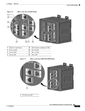
Chapter 1 Overview Figure 1-6 1 2 3 4 LEDs on the Cisco IE 3000 Switch Front-Panel Description 201703 5 67 8 1 Express setup button 2 System LED 3 Alarm LED 4 Setup LED 5 Dual-purpose uplink port LED 6 Pwr B LED 7 Pwr A LED 8 Port LED Figure 1-7 LEDs on the Cisco IEM-3000-8TM Module 201706 1 1 10/100 port LED OL-13017-01 Cisco IE 3000 Switch Hardware Installation Guide 1-7
Chapter 1 Overview Figure 1-6 1 2 3 4 LEDs on the Cisco IE 3000 Switch Front-Panel Description 201703 5 67 8 1 Express setup button 2 System LED 3 Alarm LED 4 Setup LED 5 Dual-purpose uplink port LED 6 Pwr B LED 7 Pwr A LED 8 Port LED Figure 1-7 LEDs on the Cisco IEM-3000-8TM Module 201706 1 1 10/100 port LED OL-13017-01 Cisco IE 3000 Switch Hardware Installation Guide 1-7
Installation Guide
Page 18
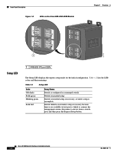
... as a managed switch. Cisco IE 3000 Switch Hardware Installation Guide 1-8 OL-13017-01 Switch failed to connect the management station. Switch is in initial setup, in initial setup. Table 1-2 lists the LED colors and their meanings. Table 1-2 Setup LED Color Off (dark) Solid green Blinking green Solid red Setup Status Switch is incomplete. Disconnect a device from a switch port, and then...
... as a managed switch. Cisco IE 3000 Switch Hardware Installation Guide 1-8 OL-13017-01 Switch failed to connect the management station. Switch is in initial setup, in initial setup. Table 1-2 lists the LED colors and their meanings. Table 1-2 Setup LED Color Off (dark) Solid green Blinking green Solid red Setup Status Switch is incomplete. Disconnect a device from a switch port, and then...

Installation Guide
Page 20
... green-amber Link fault. Error frames can remain amber for up to 30 seconds while STP checks the switch for a link-fault indication. Port was disabled by Spanning Tree Protocol (STP) is disabled. 1-10 Cisco IE 3000 Switch Hardware Installation Guide OL-13017-01 Front-Panel Description Chapter 1 Overview Note The Pwr A and Pwr B LEDs show...
... green-amber Link fault. Error frames can remain amber for up to 30 seconds while STP checks the switch for a link-fault indication. Port was disabled by Spanning Tree Protocol (STP) is disabled. 1-10 Cisco IE 3000 Switch Hardware Installation Guide OL-13017-01 Front-Panel Description Chapter 1 Overview Note The Pwr A and Pwr B LEDs show...
Installation Guide
Page 24
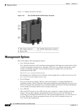
... Figure 1-12 displays the power converter. Cisco Network Assistant is enhanced to the switch management port, or a console port, or by connecting your network through a web browser. Through a GUI, users can fully configure and monitor the switch. You can configure and manage switch clusters or standalone switches. For more information. 1-14 Cisco IE 3000 Switch Hardware Installation Guide OL-13017-01...
... Figure 1-12 displays the power converter. Cisco Network Assistant is enhanced to the switch management port, or a console port, or by connecting your network through a web browser. Through a GUI, users can fully configure and monitor the switch. You can configure and manage switch clusters or standalone switches. For more information. 1-14 Cisco IE 3000 Switch Hardware Installation Guide OL-13017-01...
Installation Guide
Page 31
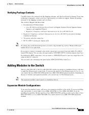
... simplified Chinese) - Cisco IE 3000 Switch Getting Started Guide (in German) • Two power and relay connectors • RJ-45 to DB-9 console port adapter cable Note To connect the switch functional ground, you need to provide an RJ-45-to the Switch The Cisco IE-3000-4TC or the Cisco IE-3000-8TC switch can operate as standalone devices. OL-13017-01 Cisco IE 3000 Switch Hardware Installation...
... simplified Chinese) - Cisco IE 3000 Switch Getting Started Guide (in German) • Two power and relay connectors • RJ-45 to DB-9 console port adapter cable Note To connect the switch functional ground, you need to provide an RJ-45-to the Switch The Cisco IE-3000-4TC or the Cisco IE-3000-8TC switch can operate as standalone devices. OL-13017-01 Cisco IE 3000 Switch Hardware Installation...
Installation Guide
Page 37
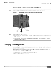
... verify that you cannot insert it out. See Figure 2-7. The card is keyed so that the switch passes the power-on the switch, and to observe POST results: • Connecting a PC or a Terminal to power on self-test (POST). Figure 2-7 Removing...the steps required to connect a PC or terminal to the switch console port, to the Console Port, page 2-12 • Verifying Switch Operation, page 2-11 OL-13017-01 Cisco IE 3000 Switch Hardware Installation Guide 2-11 Place it in place. Chapter 2 Switch Installation Verifying Switch Operation Follow these directions to protect it from the...
... verify that you cannot insert it out. See Figure 2-7. The card is keyed so that the switch passes the power-on the switch, and to observe POST results: • Connecting a PC or a Terminal to power on self-test (POST). Figure 2-7 Removing...the steps required to connect a PC or terminal to the switch console port, to the Console Port, page 2-12 • Verifying Switch Operation, page 2-11 OL-13017-01 Cisco IE 3000 Switch Hardware Installation Guide 2-11 Place it in place. Chapter 2 Switch Installation Verifying Switch Operation Follow these directions to protect it from the...
Installation Guide
Page 97
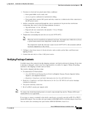
... an industrial enclosure, the temperature within reach of the connection to the DC power source. • Airflow around the switch and through the vents is missing or damaged, contact your Cisco representative or reseller for the Cisco IE 3000 Switch (safety warnings translated in German) • Two power and relay connectors • RJ-45 to DB-9 console port...
... an industrial enclosure, the temperature within reach of the connection to the DC power source. • Airflow around the switch and through the vents is missing or damaged, contact your Cisco representative or reseller for the Cisco IE 3000 Switch (safety warnings translated in German) • Two power and relay connectors • RJ-45 to DB-9 console port...
Installation Guide
Page 104
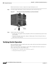
...: • Connecting a PC or a Terminal to the Console Port, page B-15 • Verifying Switch Operation, page B-14 B-14 Cisco IE 3000 Switch Hardware Installation Guide OL-13017-01 Verifying Switch Operation Appendix B Installation In a Hazardous Environment Follow these directions to protect it from the Switch 201851 Bottom 1 of the switch. These sections describe the steps required to connect a PC...
...: • Connecting a PC or a Terminal to the Console Port, page B-15 • Verifying Switch Operation, page B-14 B-14 Cisco IE 3000 Switch Hardware Installation Guide OL-13017-01 Verifying Switch Operation Appendix B Installation In a Hazardous Environment Follow these directions to protect it from the Switch 201851 Bottom 1 of the switch. These sections describe the steps required to connect a PC...
Installation Guide
Page 154
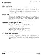
...to a console PC. See the switch release notes for this feature, see Table C-2 and Table C-3. Cisco IE 3000 Switch Hardware Installation Guide C-4 OL-13017-01 Console Port The console port uses an 8-pin RJ-45 connector, which is used with Cisco IE 3000 switches. • SFP Module Cable ...Appendix C Cable and Connectors Dual-Purpose Ports The Ethernet port on a dual-purpose port uses standard RJ-45 connectors. For console port and adapter pinout information, see the switch software configuration guide or the switch command reference. Cable and Adapter Specifications These...
...to a console PC. See the switch release notes for this feature, see Table C-2 and Table C-3. Cisco IE 3000 Switch Hardware Installation Guide C-4 OL-13017-01 Console Port The console port uses an 8-pin RJ-45 connector, which is used with Cisco IE 3000 switches. • SFP Module Cable ...Appendix C Cable and Connectors Dual-Purpose Ports The Ethernet port on a dual-purpose port uses standard RJ-45 connectors. For console port and adapter pinout information, see the switch software configuration guide or the switch command reference. Cable and Adapter Specifications These...

Installation Guide
Page 158
...-45-to -DB-9 Terminal Adapter DB-9 Pin 8 6 2 5 5 3 4 7 Console Device Signal CTS DSR RxD GND GND TxD DTR RTS Cisco IE 3000 Switch Hardware Installation Guide C-8 OL-13017-01 Table C-2 Console Port Signaling Using a DB-9 Adapter Switch Console Port (DTE) Signal RTS DTR TxD GND GND RxD DSR CTS RJ-45-to -DB-9 adapter cable, and the console...
...-45-to -DB-9 Terminal Adapter DB-9 Pin 8 6 2 5 5 3 4 7 Console Device Signal CTS DSR RxD GND GND TxD DTR RTS Cisco IE 3000 Switch Hardware Installation Guide C-8 OL-13017-01 Table C-2 Console Port Signaling Using a DB-9 Adapter Switch Console Port (DTE) Signal RTS DTR TxD GND GND RxD DSR CTS RJ-45-to -DB-9 adapter cable, and the console...

Installation Guide
Page 159
... Adapter DB-25 Pin 5 6 3 7 7 2 20 4 Console Device Signal CTS DSR RxD GND GND TxD DTR RTS OL-13017-01 Cisco IE 3000 Switch Hardware Installation Guide C-9 Table C-3 Console Port Signaling Using a DB-25 Adapter Switch Console Port (DTE) Signal RTS DTR TxD GND GND RxD DSR CTS RJ-45-to -DB-25 female DTE adapter, and the...
... Adapter DB-25 Pin 5 6 3 7 7 2 20 4 Console Device Signal CTS DSR RxD GND GND TxD DTR RTS OL-13017-01 Cisco IE 3000 Switch Hardware Installation Guide C-9 Table C-3 Console Port Signaling Using a DB-25 Adapter Switch Console Port (DTE) Signal RTS DTR TxD GND GND RxD DSR CTS RJ-45-to -DB-25 female DTE adapter, and the...


