

Parts Guide
Page 2
... CC 4 LS 27 CC Labels 20 Record Product Information To ease in ordering replacement parts, please locate the model plate on the equipment and record the information in the provided area to the most recent product information available at the time of printing. To The Owner Thank You Thank you for current color codes: 0637 4021 0499 Black Yellow (Cub Cadet) Beige (Cub Cadet...
... CC 4 LS 27 CC Labels 20 Record Product Information To ease in ordering replacement parts, please locate the model plate on the equipment and record the information in the provided area to the most recent product information available at the time of printing. To The Owner Thank You Thank you for current color codes: 0637 4021 0499 Black Yellow (Cub Cadet) Beige (Cub Cadet...
Parts Guide
Page 5
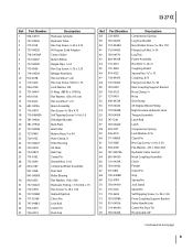
... Elbow Fitting High Pressure Hydraulic Hose Tongue Assembly Latch Rod Latch Compression Spring Lock Washer, 5/16 Clevis Pin Hex Cap Screw, 3⁄8-16 x 3.50 Flat Washer, .375 x.738 x.063 Hydraulic Valve Control Hitch Coupling Assembly Chain Fender Clevis Pin Grip Spring Pin Jack Stand Spiral Pin Self-Tapping Screw, 5⁄16-18 x 1.00 Front Coupling Support Bracket Valve Handle Link Cotter Pin, Bow Tie Hose Guard, 44" Continued on next page 5 Part Number 1 918...
... Elbow Fitting High Pressure Hydraulic Hose Tongue Assembly Latch Rod Latch Compression Spring Lock Washer, 5/16 Clevis Pin Hex Cap Screw, 3⁄8-16 x 3.50 Flat Washer, .375 x.738 x.063 Hydraulic Valve Control Hitch Coupling Assembly Chain Fender Clevis Pin Grip Spring Pin Jack Stand Spiral Pin Self-Tapping Screw, 5⁄16-18 x 1.00 Front Coupling Support Bracket Valve Handle Link Cotter Pin, Bow Tie Hose Guard, 44" Continued on next page 5 Part Number 1 918...

Parts Guide
Page 9
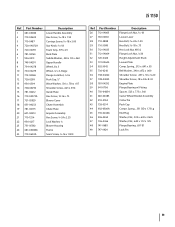
... Assembly Latch Rod Latch Compression Spring Flat Washer Clevis Pin Hex Cap Screw, 3⁄8-16 x 3.50 Flat Washer, .375 x.738 x.063 Hydraulic Valve Control Hitch Coupling Assembly Chain Fender Clevis Pin Grip Spring Pin Jack Stand Spiral Pin Plastic Bushing, .380 ID Self-Tapping Screw, 5⁄16-18 x 1.00 Valve Handle Link Cotter Pin, Bow Tie Hose Guard, 44" Hose Guard, 48" Set Screws Coupling, .875 Spider Bushing Coupling, .500 9 LS 25 CC Ref. Part Number...
... Assembly Latch Rod Latch Compression Spring Flat Washer Clevis Pin Hex Cap Screw, 3⁄8-16 x 3.50 Flat Washer, .375 x.738 x.063 Hydraulic Valve Control Hitch Coupling Assembly Chain Fender Clevis Pin Grip Spring Pin Jack Stand Spiral Pin Plastic Bushing, .380 ID Self-Tapping Screw, 5⁄16-18 x 1.00 Valve Handle Link Cotter Pin, Bow Tie Hose Guard, 44" Hose Guard, 48" Set Screws Coupling, .875 Spider Bushing Coupling, .500 9 LS 25 CC Ref. Part Number...
Parts Guide
Page 11
...;16-18 x 2.00 Star Knob, 5⁄16-18 Foam Grip, .970 x 25 Back Plate Saddle Washer, .320 x .93 x .060 Upper Handle Wheel, 8 x 3 Wheel, 12 x 3, Beige Flange Lock Nut, 3⁄8-16 Push Cap, 1⁄2" Wave Washer, .510 x .750 x .017 Shoulder Screw, .625 x 3.94 Guide Plate Hex Screw, 12-16 x .75 Blower Cover Chute Assembly Chute Plate Impeler Assembly Hex Screw, 3⁄8-24 x 2.25 Lock Washer, 3⁄8 Blower Housing Frame Sems Screw, 3⁄8-16 x 1.000...
...;16-18 x 2.00 Star Knob, 5⁄16-18 Foam Grip, .970 x 25 Back Plate Saddle Washer, .320 x .93 x .060 Upper Handle Wheel, 8 x 3 Wheel, 12 x 3, Beige Flange Lock Nut, 3⁄8-16 Push Cap, 1⁄2" Wave Washer, .510 x .750 x .017 Shoulder Screw, .625 x 3.94 Guide Plate Hex Screw, 12-16 x .75 Blower Cover Chute Assembly Chute Plate Impeler Assembly Hex Screw, 3⁄8-24 x 2.25 Lock Washer, 3⁄8 Blower Housing Frame Sems Screw, 3⁄8-16 x 1.000...

Parts Guide
Page 17
...Housing Chipper Chute Assembly Hose Cradle Flange Lock Nut, 1/4-20 Spacer Hose Nozzle Hex Cap Screw 1/4-20 x 2.625 Adjustment Clamp Nozzle Handle CSV Model 050 Ref No. 30 31 32 33 34 35 36 37 38 39 40 41 42 43 44 45 46 47 48 49 50 51 52 53 54 55 56 57 Part Number...Vacuum Hose Handle Plug Hose Adapter Cap Lock Nut, 1/4-20 TT Screw, 5/16-18 x .750 Front Wheel Support Brace Rear Wheel Support Brace Handle Bracket Ass'y RH Handle Brkt Ass'y LH Cotter Pin Push Cap Axle HHflg, 3/8-16 x .875 Height Adjustment Bearing Pivot Arm Assembly Height Adjustment Knob Spring Lever Height Lever Assembly (Incl....
...Housing Chipper Chute Assembly Hose Cradle Flange Lock Nut, 1/4-20 Spacer Hose Nozzle Hex Cap Screw 1/4-20 x 2.625 Adjustment Clamp Nozzle Handle CSV Model 050 Ref No. 30 31 32 33 34 35 36 37 38 39 40 41 42 43 44 45 46 47 48 49 50 51 52 53 54 55 56 57 Part Number...Vacuum Hose Handle Plug Hose Adapter Cap Lock Nut, 1/4-20 TT Screw, 5/16-18 x .750 Front Wheel Support Brace Rear Wheel Support Brace Handle Bracket Ass'y RH Handle Brkt Ass'y LH Cotter Pin Push Cap Axle HHflg, 3/8-16 x .875 Height Adjustment Bearing Pivot Arm Assembly Height Adjustment Knob Spring Lever Height Lever Assembly (Incl....
Parts Guide
Page 65
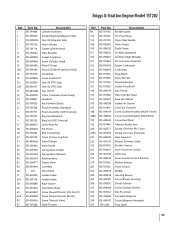
... Kit-Idle Speed Pin-Float Hinge Valve-Float Needle Valve-Choke Shaft-Choke Jet-Main (Standard) Jet-Main (High Altitude) Kit-Carburetor Overhaul Spacer-Carburetor Carburetor Plug-Welch Valve-Throttle Float-Carburetor Gasket-Float Bowl Key-Timing Plate-Cylinder Head Base-Air Cleaner Gasket-Air Cleaner Line-Fuel (Formed) Screw (Control Bracket) (M6x14.73mm) Screw (Control Bracket) (M5x9.5mm) Screw (Fuel Tank) Adjustor-Rocker Arm Spring-Governor (No Color) Spring-Governor (Platinum) Gear-Governor Washer (Governor Gear) Bracket-Control Lever-Governor Control Valve-Cap Lever-Control (Control...
... Kit-Idle Speed Pin-Float Hinge Valve-Float Needle Valve-Choke Shaft-Choke Jet-Main (Standard) Jet-Main (High Altitude) Kit-Carburetor Overhaul Spacer-Carburetor Carburetor Plug-Welch Valve-Throttle Float-Carburetor Gasket-Float Bowl Key-Timing Plate-Cylinder Head Base-Air Cleaner Gasket-Air Cleaner Line-Fuel (Formed) Screw (Control Bracket) (M6x14.73mm) Screw (Control Bracket) (M5x9.5mm) Screw (Fuel Tank) Adjustor-Rocker Arm Spring-Governor (No Color) Spring-Governor (Platinum) Gear-Governor Washer (Governor Gear) Bracket-Control Lever-Governor Control Valve-Cap Lever-Control (Control...
Parts Guide
Page 66
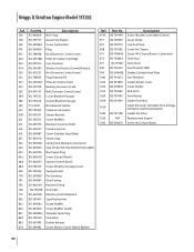
...Control Lever) Plug-Dipstick/Fill Filter-Air Cleaner Foam Bushing-Governor Crank Bolt (Governor Control Lever) Cover-Breather Passage Gasket-Breather Passage Nut (Rewind Starter) Clamp-Hose (Green) Starter-Rewind Screw (Muffler) Retainer-Governor Shaft Crank-Governor Screw (Cylinder Head Plate) Switch-Stop Spring/Link-Mechanical Governor Seal-Choke/Throttle Shaft (Choke Shaft) Boot-Spark Plug Screw (Control Panel) Spacer (Control Panel) Screw (Breather Passage Cover) Spring-Detent Pin-Locating Gear-Timing Retainer-E Ring Gear-Idler Retainer (Control Bracket) Stud-Rocker Arm Guard-Muffler Screw...
...Control Lever) Plug-Dipstick/Fill Filter-Air Cleaner Foam Bushing-Governor Crank Bolt (Governor Control Lever) Cover-Breather Passage Gasket-Breather Passage Nut (Rewind Starter) Clamp-Hose (Green) Starter-Rewind Screw (Muffler) Retainer-Governor Shaft Crank-Governor Screw (Cylinder Head Plate) Switch-Stop Spring/Link-Mechanical Governor Seal-Choke/Throttle Shaft (Choke Shaft) Boot-Spark Plug Screw (Control Panel) Spacer (Control Panel) Screw (Breather Passage Cover) Spring-Detent Pin-Locating Gear-Timing Retainer-E Ring Gear-Idler Retainer (Control Bracket) Stud-Rocker Arm Guard-Muffler Screw...

Operation Manual
Page 1
... Operation Practices • Set-Up • Operation • Service • Troubleshooting • Warranty Operator's Manual LS 25 CC & LS 27 CCHP - Not all features in this manual are applicable to all models and the model depicted may vary by model. NOTE: This Operator's Manual covers several models. CUB CADET LLC, P.O. BOX 361131 CLEVELAND, OHIO 44136-0019 QR Code for manufacturing purposes only. Log Splitter WARNING READ AND FOLLOW ALL SAFETY RULES AND INSTRUCTIONS IN...
... Operation Practices • Set-Up • Operation • Service • Troubleshooting • Warranty Operator's Manual LS 25 CC & LS 27 CCHP - Not all features in this manual are applicable to all models and the model depicted may vary by model. NOTE: This Operator's Manual covers several models. CUB CADET LLC, P.O. BOX 361131 CLEVELAND, OHIO 44136-0019 QR Code for manufacturing purposes only. Log Splitter WARNING READ AND FOLLOW ALL SAFETY RULES AND INSTRUCTIONS IN...

Operation Manual
Page 2
... and/or illustrated in this manual, all times. Cub Cadet's Customer Support telephone numbers, website address and mailing address can seek help from the experts. Throughout this manual may cover a range of Contents Safe Operation Practices 3 Assembly & Set-Up 5 Controls & Operation 7 Service 9 Troubleshooting 11 Replacement Parts 13 Warranty 14 Español Record Product Information Before setting up , operate and maintain your new equipment, please locate the model plate on the equipment and...
... and/or illustrated in this manual, all times. Cub Cadet's Customer Support telephone numbers, website address and mailing address can seek help from the experts. Throughout this manual may cover a range of Contents Safe Operation Practices 3 Assembly & Set-Up 5 Controls & Operation 7 Service 9 Troubleshooting 11 Replacement Parts 13 Warranty 14 Español Record Product Information Before setting up , operate and maintain your new equipment, please locate the model plate on the equipment and...
Operation Manual
Page 3
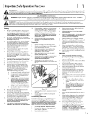
... poisoning, gangrene, or death. Never remove gas cap or add fuel while the engine is capable of yourself and others. Replace gasoline cap and tighten securely. 8. Allow machine to comply with any type of power equipment, carelessness or error on the part of Origin" is an open flame, spark or pilot light as on this machine. 3. Operation 1. Failure to cool at least two...
... poisoning, gangrene, or death. Never remove gas cap or add fuel while the engine is capable of yourself and others. Replace gasoline cap and tighten securely. 8. Allow machine to comply with any type of power equipment, carelessness or error on the part of Origin" is an open flame, spark or pilot light as on this machine. 3. Operation 1. Failure to cool at least two...

Operation Manual
Page 4
... the use of operation. 11. and ground it . Immediately remove split wood around the machine so you do not meet the original equipment 18. If the engine is running ; Replace if 15. Horizontal Operating Position: Stand they are tight to persons who read, understand and follow all mechanical and safety systems are working order by cycling the valve control lever fingers. Spark Arrestor WARNING...
... the use of operation. 11. and ground it . Immediately remove split wood around the machine so you do not meet the original equipment 18. If the engine is running ; Replace if 15. Horizontal Operating Position: Stand they are tight to persons who read, understand and follow all mechanical and safety systems are working order by cycling the valve control lever fingers. Spark Arrestor WARNING...
Operation Manual
Page 5
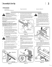
...; Engine Operator's Manual (1) • Tongue Assembly (1) • Operator's Manual (1) WARNING! See Figure 3-5. Unpacking & Assembling the Log Splitter TOOLS NEEDED: Safety glasses, leather gloves, wire cutters, pry bar and/or claw hammer. 1. Hex Screws Tank Brackets Hex Bolts Figure 3-2 Align the holes in the tongue with the holes in the tank bracket and secure with the beam in the beam. Do NOT remove any wood or cut any...
...; Engine Operator's Manual (1) • Tongue Assembly (1) • Operator's Manual (1) WARNING! See Figure 3-5. Unpacking & Assembling the Log Splitter TOOLS NEEDED: Safety glasses, leather gloves, wire cutters, pry bar and/or claw hammer. 1. Hex Screws Tank Brackets Hex Bolts Figure 3-2 Align the holes in the tongue with the holes in the tank bracket and secure with the beam in the beam. Do NOT remove any wood or cut any...

Operation Manual
Page 6
.... Check the fluid level using the dipstick. Do not overfill. Disconnect the spark plug and prime the pump by pulling the recoil starter as far as the system builds heat and the fluid expands and seeks a balanced level. 6 Section 3- Refill the tank as instructed in the tray with force sufficient to the control valve side of the beam, aligning the holes in the engine manual...
.... Check the fluid level using the dipstick. Do not overfill. Disconnect the spark plug and prime the pump by pulling the recoil starter as far as the system builds heat and the fluid expands and seeks a balanced level. 6 Section 3- Refill the tank as instructed in the tray with force sufficient to the control valve side of the beam, aligning the holes in the engine manual...
Operation Manual
Page 7
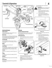
... Engine Operator's Manual for instructions on starting and Beam Locks stopping the engine. The horizontal beam lock is lowered into position. Block the front and back of the engine controls. Log Dislodger The log dislodger is heavy. End Plate Figure 4-2 3. The spring loaded lock will snap into place. Pull the horizontal beam lock out to release the beam and pivot the beam to the oil filter. To lock...
... Engine Operator's Manual for instructions on starting and Beam Locks stopping the engine. The horizontal beam lock is lowered into position. Block the front and back of the engine controls. Log Dislodger The log dislodger is heavy. End Plate Figure 4-2 3. The spring loaded lock will snap into place. Pull the horizontal beam lock out to release the beam and pivot the beam to the oil filter. To lock...

Operation Manual
Page 8
... adjustment nut one turn clockwise. Attempt to the NEUTRAL position manually, if necessary. Move the control handle to the FORWARD position to move the lever to the NEUTRAL position to stop wedge) REVERSE (To return wedge) Figure 4-5 • FORWARD - WARNING! Contact an authorized service dealer. Start the engine as instructed in the direction of the grain. 3. Place the log against the tongue. Adult who operates...
... adjustment nut one turn clockwise. Attempt to the NEUTRAL position manually, if necessary. Move the control handle to the FORWARD position to move the lever to the NEUTRAL position to stop wedge) REVERSE (To return wedge) Figure 4-5 • FORWARD - WARNING! Contact an authorized service dealer. Start the engine as instructed in the direction of the grain. 3. Place the log against the tongue. Adult who operates...

Operation Manual
Page 9
... tank, hydraulic pump or valve is recommended that fluids not be changed with top of the original fluid has been drawn into a suitable container. 15. Figure 5-2, refer to Figure 5-2 for vertical engines. Reconnect the spark plug wire and start the engine following the instructions in the reservoir tank. Carefully un-thread the inlet filter and clean it against the engine and relieving the hydraulic system pressure...
... tank, hydraulic pump or valve is recommended that fluids not be changed with top of the original fluid has been drawn into a suitable container. 15. Figure 5-2, refer to Figure 5-2 for vertical engines. Reconnect the spark plug wire and start the engine following the instructions in the reservoir tank. Carefully un-thread the inlet filter and clean it against the engine and relieving the hydraulic system pressure...

Operation Manual
Page 10
... fertilizer. Disconnect the spark plug wire and ground it next to the Engine Operator's manual packed with engine oil. Loosen the set screw. 12. Install the nylon "spider" onto the engine coupling half. 8. Secure with a light oil or silicone. 10 Section 5- NOTE: Make certain the proper clearance/gap is obtained before tightening the set screw on the off the engine shaft. 6. NOTE: Using a pressure washer or garden house to secure the...
... fertilizer. Disconnect the spark plug wire and ground it next to the Engine Operator's manual packed with engine oil. Loosen the set screw. 12. Install the nylon "spider" onto the engine coupling half. 8. Secure with a light oil or silicone. 10 Section 5- NOTE: Make certain the proper clearance/gap is obtained before tightening the set screw on the off the engine shaft. 6. NOTE: Using a pressure washer or garden house to secure the...

Operation Manual
Page 11
... Damaged relief valve. 7. Blocked control valve. See authorized service dealer. 5. Troubleshooting 6 Problem Cylinder rod will not move Cause 1. Broken drive shaft. 2. Shipping plugs left in coupling not adjusted properly. 4. Set screws in hydraulic hoses. 3. Loose shaft coupling. 5. Hydraulic lines blocked. 8. Incorrect oil level. 9. See authorized service dealer. 4. Correct engine/pump alignment as necessary. 5. See authorized service dealer. 6. See authorized service dealer. 7. Check oil level. 9. Flush and clean hydraulic system. Slow cylinder shaft speed while...
... Damaged relief valve. 7. Blocked control valve. See authorized service dealer. 5. Troubleshooting 6 Problem Cylinder rod will not move Cause 1. Broken drive shaft. 2. Shipping plugs left in coupling not adjusted properly. 4. Set screws in hydraulic hoses. 3. Loose shaft coupling. 5. Hydraulic lines blocked. 8. Incorrect oil level. 9. See authorized service dealer. 4. Correct engine/pump alignment as necessary. 5. See authorized service dealer. 6. See authorized service dealer. 7. Check oil level. 9. Flush and clean hydraulic system. Slow cylinder shaft speed while...

Operation Manual
Page 13
..., BG5H) Engine Coupling, .750 (BG55) Pump Coupling, .500 Set Screw Hydraulic Oil Filter 737-04308 727-04290 727-0451 727-04356 727-04288 727-0443 727-04362 Inlet Filter Inlet Hose (BF55) Inlet Hose (BG5H) Inlet Hose (BG55) Hydro Hose Return Hose Hydro Hose 726-0132 Hose Clamp 634-0187 Wheel, 16.0 x 4.8 x 8.0 N/A Spark Plug (See Engine Operator's Manual) N/A Fuel Filter (See Engine Operator's Manual) N/A Air Filter (See Engine Operator's Manual) Cub Cadet Genuine Parts can be...
..., BG5H) Engine Coupling, .750 (BG55) Pump Coupling, .500 Set Screw Hydraulic Oil Filter 737-04308 727-04290 727-0451 727-04356 727-04288 727-0443 727-04362 Inlet Filter Inlet Hose (BF55) Inlet Hose (BG5H) Inlet Hose (BG55) Hydro Hose Return Hose Hydro Hose 726-0132 Hose Clamp 634-0187 Wheel, 16.0 x 4.8 x 8.0 N/A Spark Plug (See Engine Operator's Manual) N/A Fuel Filter (See Engine Operator's Manual) N/A Air Filter (See Engine Operator's Manual) Cub Cadet Genuine Parts can be...

Operation Manual
Page 14
... Operator's Manual furnished with the product, and has not been subject to misuse, abuse, neglect, accident, improper maintenance, alteration, vandalism, theft, fire, water, or damage because of other express warranty, whether written or oral, except as lubricants, filters, blade sharpening, tune-ups, brake adjustments, clutch adjustments, deck adjustments, and normal deterioration of the exterior finish due to use : Cub Cadet warrants this warranty. c. CUB CADET LLC MANUFACTURER'S LIMITED WARRANTY...
... Operator's Manual furnished with the product, and has not been subject to misuse, abuse, neglect, accident, improper maintenance, alteration, vandalism, theft, fire, water, or damage because of other express warranty, whether written or oral, except as lubricants, filters, blade sharpening, tune-ups, brake adjustments, clutch adjustments, deck adjustments, and normal deterioration of the exterior finish due to use : Cub Cadet warrants this warranty. c. CUB CADET LLC MANUFACTURER'S LIMITED WARRANTY...


