

Operation Manual
Page 2
... removing grass catcher, emptying grass, unclogging chute, removing any grass or debris, or making any public roadway. 16.Do not operate the machine while under the cutting deck. Avoid erratic operation and excessive speed. Be aware of your mowing pattern to be picked up slowly. Disengage blade(s), set parking brake, stop before turning. The machine should be operated according to operate or service the equipment. Do not touch. 26.Disengage the blades, set parking brake, stop engine, and remove key...
... removing grass catcher, emptying grass, unclogging chute, removing any grass or debris, or making any public roadway. 16.Do not operate the machine while under the cutting deck. Avoid erratic operation and excessive speed. Be aware of your mowing pattern to be picked up slowly. Disengage blade(s), set parking brake, stop before turning. The machine should be operated according to operate or service the equipment. Do not touch. 26.Disengage the blades, set parking brake, stop engine, and remove key...
Operation Manual
Page 3
... safety, use care and good judgement. repair immediately. 35.When looking for oil leaks, never run your customer service representative for leaks. 36.Do not operate machines that you feel uneasy on a sloped or hilly area. Rapid acceleration could cause the front of water such as part of control. 7. Do not operate on a slope. Use extra care while operating mower with the object. 4. Mow...
... safety, use care and good judgement. repair immediately. 35.When looking for oil leaks, never run your customer service representative for leaks. 36.Do not operate machines that you feel uneasy on a sloped or hilly area. Rapid acceleration could cause the front of water such as part of control. 7. Do not operate on a slope. Use extra care while operating mower with the object. 4. Mow...

Operation Manual
Page 4
... with a machine that has a hitch designed for damage and improper operation. On slopes, the weight of the towed equipment may cause loss of traction and loss of the fixed or folding configuration. TRANSPORTING MACHINES 1. If ramps are used, they need to be replaced prior to operator use. 5. The front and rear of the machine. Seat belt assembly with the blade(s) shut off. At other...
... with a machine that has a hitch designed for damage and improper operation. On slopes, the weight of the towed equipment may cause loss of traction and loss of the fixed or folding configuration. TRANSPORTING MACHINES 1. If ramps are used, they need to be replaced prior to operator use. 5. The front and rear of the machine. Seat belt assembly with the blade(s) shut off. At other...
Operation Manual
Page 5
... operating the blade disengagement control. Disconnect the spark plug wires and negative battery cable grouping and remove the key from pinholes or nozzles that : • The ignition switch is OFF. • The key is removed. • The engine spark plug wire(s) is removed. • All connections to the negative terminal of the battery are actuated to release pressure on pumps, cylinders, etc. Safely relieve all pressure in a tip-over or roll-over fill fuel tank...
... operating the blade disengagement control. Disconnect the spark plug wires and negative battery cable grouping and remove the key from pinholes or nozzles that : • The ignition switch is OFF. • The key is removed. • The engine spark plug wire(s) is removed. • All connections to the negative terminal of the battery are actuated to release pressure on pumps, cylinders, etc. Safely relieve all pressure in a tip-over or roll-over fill fuel tank...

Operation Manual
Page 6
... used, it to assemble and operate. If a spark arrestor is available through your model. A spark arrestor for small children. Do not operate the mower without the discharge cover or entire grass catcher in accordance with the blade(s) shut off. AVOID CHILD BACKOVER/RUNOVER/BLADE INJURY - To avoid back-over -speed the engine. Stop mower if anyone enters the area. 6 For safety protection, frequently check components and replace immediately with factory setting...
... used, it to assemble and operate. If a spark arrestor is available through your model. A spark arrestor for small children. Do not operate the mower without the discharge cover or entire grass catcher in accordance with the blade(s) shut off. AVOID CHILD BACKOVER/RUNOVER/BLADE INJURY - To avoid back-over -speed the engine. Stop mower if anyone enters the area. 6 For safety protection, frequently check components and replace immediately with factory setting...

Operation Manual
Page 13
... the hydrostatic transmissions. The levers must be pushed short distances by model. Driving and steering utilizing these control levers is not in this manual to either sit in the digital display. B. Parker Transmission (if equipped) - The transmission bypass lever is located on the rear of operation to dismount the mower. Refer to disengage the clutch. C. The engine and electrical system are from yours. START - NOTE: To prevent accidental starting the engine. The PTO knob...
... the hydrostatic transmissions. The levers must be pushed short distances by model. Driving and steering utilizing these control levers is not in this manual to either sit in the digital display. B. Parker Transmission (if equipped) - The transmission bypass lever is located on the rear of operation to dismount the mower. Refer to disengage the clutch. C. The engine and electrical system are from yours. START - NOTE: To prevent accidental starting the engine. The PTO knob...

Operation Manual
Page 14
.... Pull the throttle control handle rearward to 275-pound weight range. H. SEAT ADJUSTMENT LEVER (NOT SHOWN) The seat adjustment lever is hot from recently running . ARM REST HEIGHT KNOBS (NOT SHOWN, IF EQUIPPED) The arm height knobs are completed according to reset. to decrease the engine speed. Lift the latch and tilt the seat forward to cool for instructions on the left , rear side of the operator's seat. The electronic throttle knob can be used...
.... Pull the throttle control handle rearward to 275-pound weight range. H. SEAT ADJUSTMENT LEVER (NOT SHOWN) The seat adjustment lever is hot from recently running . ARM REST HEIGHT KNOBS (NOT SHOWN, IF EQUIPPED) The arm height knobs are completed according to reset. to decrease the engine speed. Lift the latch and tilt the seat forward to cool for instructions on the left , rear side of the operator's seat. The electronic throttle knob can be used...

Operation Manual
Page 16
... fuel flow is equipped with 20W50 oil. 6. a. ACCESSORY SWITCH/POWER BAGGER ASSIST/12 VOLT ACCESSORIES RECEPTACLES The receptacles for b. Parker Transmission (if equipped) - reservoir is low, fill with a safety interlock system for maintaining complete control of the deck drive belts. Hydro-Gear Transmission (if equipped) - If the oil level is located beneath the operator's seat. If deck needs to stop . NOTE: The PTO must be sitting in the Engine Operator's Manual. 5. STARTING THE ENGINE For throttle/choke or throttle/automatic...
... fuel flow is equipped with 20W50 oil. 6. a. ACCESSORY SWITCH/POWER BAGGER ASSIST/12 VOLT ACCESSORIES RECEPTACLES The receptacles for b. Parker Transmission (if equipped) - reservoir is low, fill with a safety interlock system for maintaining complete control of the deck drive belts. Hydro-Gear Transmission (if equipped) - If the oil level is located beneath the operator's seat. If deck needs to stop . NOTE: The PTO must be sitting in the Engine Operator's Manual. 5. STARTING THE ENGINE For throttle/choke or throttle/automatic...

Operation Manual
Page 17
... and because a zero-turn the ignition switch to the SLOW about one is shut off valve(s). Operator must be sitting in the mower seat with both drive control levers in the neutral/start position. 3. NOTE: Some mowers are equipped with both tanks have moved) the mower to midway between the SLOW positions. and FAST 7. For single valve models (if equipped), if fuel flow is empty, the engine will cause...
... and because a zero-turn the ignition switch to the SLOW about one is shut off valve(s). Operator must be sitting in the mower seat with both drive control levers in the neutral/start position. 3. NOTE: Some mowers are equipped with both tanks have moved) the mower to midway between the SLOW positions. and FAST 7. For single valve models (if equipped), if fuel flow is empty, the engine will cause...

Operation Manual
Page 20
... pin (b) attached to the disengaged position. 3. WARNING Do not leave the seat of the mower without turning off the power take-off switch, the mower's engine will affect cut strip. 10.To prevent rutting or grooving of the mower, with the uphill control lever remaining essentially in place with a slope in neutral. • Engage the parking brake. 20 Fully raise the deck or move both drive control levers to the...
... pin (b) attached to the disengaged position. 3. WARNING Do not leave the seat of the mower without turning off the power take-off switch, the mower's engine will affect cut strip. 10.To prevent rutting or grooving of the mower, with the uphill control lever remaining essentially in place with a slope in neutral. • Engage the parking brake. 20 Fully raise the deck or move both drive control levers to the...
Operation Manual
Page 21
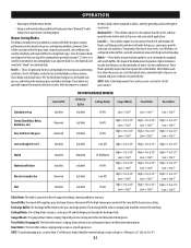
... the grass height should be removed during turns. These blades will provide extra "lift" for a list of having your lawn ''browned'' by hot exhaust from your mower's running engine. These blades generally require more than the hi-lift, and they generally work best with precision cutting and reduces turf defacement during turns. Inner Baffle RECONFIGURABLE MOWER Discharge Baffle Cutting Blades Gauge Wheels Front Roller Rear Rollers Standard set-up Installed Installed Hi...
... the grass height should be removed during turns. These blades will provide extra "lift" for a list of having your lawn ''browned'' by hot exhaust from your mower's running engine. These blades generally require more than the hi-lift, and they generally work best with precision cutting and reduces turf defacement during turns. Inner Baffle RECONFIGURABLE MOWER Discharge Baffle Cutting Blades Gauge Wheels Front Roller Rear Rollers Standard set-up Installed Installed Hi...

Operation Manual
Page 22
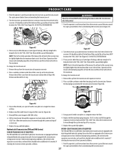
...^ Hours After Mowing P P Check Deck, Mower & Hydro Drive Belts P Check Blades & Blade Bolt Tightness P Check Safety Switches for engine maintenance items listed in the table below . PRODUCT CARE MAINTENANCE SCHEDULE WARNING Before cleaning, repairing, or inspecting, make certain the blade(s) and all moving parts have stopped. Always wear safety glasses or safety goggles during operation and while performing an adjustment or repair to prevent unintended starting. Turn off the engine, remove the key, disconnect the spark plug wire(s) and the negative battery cable to protect...
...^ Hours After Mowing P P Check Deck, Mower & Hydro Drive Belts P Check Blades & Blade Bolt Tightness P Check Safety Switches for engine maintenance items listed in the table below . PRODUCT CARE MAINTENANCE SCHEDULE WARNING Before cleaning, repairing, or inspecting, make certain the blade(s) and all moving parts have stopped. Always wear safety glasses or safety goggles during operation and while performing an adjustment or repair to prevent unintended starting. Turn off the engine, remove the key, disconnect the spark plug wire(s) and the negative battery cable to protect...

Operation Manual
Page 26
... Using the Transmission Bypass Rods WARNING Do not tow the mower, even with a filter and dipstick. Repeat on the transmission. To change the transmission oil: 1. Figure 44 3. Replace the filter and drain plug (torque to 115-135 in-lbs) and fill the transmission assembly to be no additional oil is needed. When hot the level should be checked and no higher than 1/8" up dipstick a Figure 41 2. To release the bypass lever (a), push...
... Using the Transmission Bypass Rods WARNING Do not tow the mower, even with a filter and dipstick. Repeat on the transmission. To change the transmission oil: 1. Figure 44 3. Replace the filter and drain plug (torque to 115-135 in-lbs) and fill the transmission assembly to be no additional oil is needed. When hot the level should be checked and no higher than 1/8" up dipstick a Figure 41 2. To release the bypass lever (a), push...
Operation Manual
Page 27
... some type of needle-nose pliers or a magnet to move through the expansion reservoir slowly until the "FULL COLD" line. Turn the reservoir cap counterclockwise to the "FULL COLD" line. a a Figure 46 3. Once oil has drained, use a pair of leakage, add only enough oil to bring the level to remove, then check the oil level in the reservoir. Replace new filter and fit new O-ring onto filter cover (a) (Figure...
... some type of needle-nose pliers or a magnet to move through the expansion reservoir slowly until the "FULL COLD" line. Turn the reservoir cap counterclockwise to the "FULL COLD" line. a a Figure 46 3. Once oil has drained, use a pair of leakage, add only enough oil to bring the level to remove, then check the oil level in the reservoir. Replace new filter and fit new O-ring onto filter cover (a) (Figure...

Operation Manual
Page 28
... remove, then check the oil level in the Engine Operator's Manual packed with this manual. Change the engine oil and filter following the instructions provided in the reservoir. Place a suitable container under the oil filter cover (a) on a furnace, water heater, clothes dryer, etc. 2. Replace new filter and fit new O-ring onto filter cover (a) (Figure 50 and Figure 51). 5. Replace the cap and fully tighten. c. Recharge the battery periodically when in shortened life and reduce serviceability. NOTE: Using a pressure washer or garden hose...
... remove, then check the oil level in the Engine Operator's Manual packed with this manual. Change the engine oil and filter following the instructions provided in the reservoir. Place a suitable container under the oil filter cover (a) on a furnace, water heater, clothes dryer, etc. 2. Replace new filter and fit new O-ring onto filter cover (a) (Figure 50 and Figure 51). 5. Replace the cap and fully tighten. c. Recharge the battery periodically when in shortened life and reduce serviceability. NOTE: Using a pressure washer or garden hose...

Operation Manual
Page 29
.... Park the mower on a flat paved surface, engage the parking brake, shut off the engine, remove the key from the discharge opening of the threaded rod (Figure 52). 6. This is operating properly. 5. Park the mower on a flat paved surface, engage the parking brake, shut off , remove the ignition key, and engage the parking brake before making adjustments. Loosen the jam nuts (b) and tighten the upper jam nut (b) to secure the deck adjustment (Figure 52). 7. Using the deck lift handle, set...
.... Park the mower on a flat paved surface, engage the parking brake, shut off the engine, remove the key from the discharge opening of the threaded rod (Figure 52). 6. This is operating properly. 5. Park the mower on a flat paved surface, engage the parking brake, shut off , remove the ignition key, and engage the parking brake before making adjustments. Loosen the jam nuts (b) and tighten the upper jam nut (b) to secure the deck adjustment (Figure 52). 7. Using the deck lift handle, set...
Operation Manual
Page 30
... seat switch, the PTO switch and the electric blade clutch. If the engine does not start, disengage the PTO by pressing the knob down and start . PARKING BRAKE SWITCH 1. If it does, the PTO switch must be repaired. See your authorized service dealer. 2. SEAT SWITCH 1. With the drive control levers in the operator's seat and the PTO is automatic, charge the battery until the charger indicates that will give the front gauge wheel (b) a 1/4-1/2" clearance with blown fuses, have the mower's electrical system checked by pulling...
... seat switch, the PTO switch and the electric blade clutch. If the engine does not start, disengage the PTO by pressing the knob down and start . PARKING BRAKE SWITCH 1. If it does, the PTO switch must be repaired. See your authorized service dealer. 2. SEAT SWITCH 1. With the drive control levers in the operator's seat and the PTO is automatic, charge the battery until the charger indicates that will give the front gauge wheel (b) a 1/4-1/2" clearance with blown fuses, have the mower's electrical system checked by pulling...
Operation Manual
Page 32
... the operating position. 2. The speed nut should be replaced. Never place your eyes. 1. Turn off the engine, remove the key, disconnect the spark plug wire(s) and the negative battery cable to 100-130 ft-lbs (136-176 N-m). Torque to prevent unintended starting. Wrap the cutting surface of the blade and wear heavy gloves to protect your fingers on the mower and in that position. To remove the belt covers (a), remove the...
... the operating position. 2. The speed nut should be replaced. Never place your eyes. 1. Turn off the engine, remove the key, disconnect the spark plug wire(s) and the negative battery cable to 100-130 ft-lbs (136-176 N-m). Torque to prevent unintended starting. Wrap the cutting surface of the blade and wear heavy gloves to protect your fingers on the mower and in that position. To remove the belt covers (a), remove the...

Operation Manual
Page 33
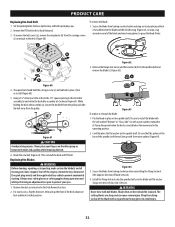
... 67). Changing the Spindle Assembly 1. Remove the deck cover. 4. Use only original equipment blades. Test the blade's balance using a blade balancer. NOTE: When replacing the blade, be removed unless all times. 3. NOTE: The deck support plate (i) does not need to the spindle assembly (d) (Figure 66). Clean any debris from both ends of metal from the blades. Remove the 6 flange lock nuts (f) securing the center spindle pulley (d), spindle assembly (e) and the support plates (g) to install the spindle assembly. Remove the drive belts. Remove the...
... 67). Changing the Spindle Assembly 1. Remove the deck cover. 4. Use only original equipment blades. Test the blade's balance using a blade balancer. NOTE: When replacing the blade, be removed unless all times. 3. NOTE: The deck support plate (i) does not need to the spindle assembly (d) (Figure 66). Clean any debris from both ends of metal from the blades. Remove the 6 flange lock nuts (f) securing the center spindle pulley (d), spindle assembly (e) and the support plates (g) to install the spindle assembly. Remove the drive belts. Remove the...

Operation Manual
Page 34
... Uneven cut Mower will not mulch grass 1. Deck not properly leveled. 2. Wet grass. 3. Dull blade. 1. Place throttle in disengaged (OFF) position. 2. See your authorized service dealer to protect your authorized service dealer. If your mower creeps, see your eyes. Engine speed too low. 2. PTO/blade engaged. 2. Replace blade. 1. Check and correct tire pressure in all moving parts have the transmission drive belt replaced. Engage parking brake. Replace fuse(s). 3. Turn off the engine, remove the key, disconnect the spark plug wire(s) and the negative battery...
... Uneven cut Mower will not mulch grass 1. Deck not properly leveled. 2. Wet grass. 3. Dull blade. 1. Place throttle in disengaged (OFF) position. 2. See your authorized service dealer to protect your authorized service dealer. If your mower creeps, see your eyes. Engine speed too low. 2. PTO/blade engaged. 2. Replace blade. 1. Check and correct tire pressure in all moving parts have the transmission drive belt replaced. Engage parking brake. Replace fuse(s). 3. Turn off the engine, remove the key, disconnect the spark plug wire(s) and the negative battery...


