User Manual 1.00 WW
Page 2
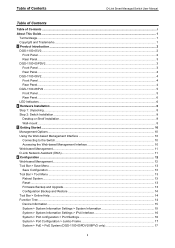
......4 DGS-1100-08PV2 ...5 Front Panel ...5 Rear Panel...6 LED Indicators...6 2 Hardware Installation ...8 Step 1: Unpacking ...8 Step 2: Switch Installation ...8 Desktop or Shelf Installation...8 Wall-mount ...8 3 Getting Started ...10 Management Options...10 Using the Web-based Management Interface 10 Connecting to the Switch...10 Accessing the Web-based Management Interface 10 Web-based Management...11 D-Link Network Assistant (DNA) ...11 4 Configuration ...12 Web-based Management...12 Tool Bar > Save Menu ...13 Save Configuration ...13 Tool Bar > Tool Menu ...13 Reboot System ...13 Reset...
......4 DGS-1100-08PV2 ...5 Front Panel ...5 Rear Panel...6 LED Indicators...6 2 Hardware Installation ...8 Step 1: Unpacking ...8 Step 2: Switch Installation ...8 Desktop or Shelf Installation...8 Wall-mount ...8 3 Getting Started ...10 Management Options...10 Using the Web-based Management Interface 10 Connecting to the Switch...10 Accessing the Web-based Management Interface 10 Web-based Management...11 D-Link Network Assistant (DNA) ...11 4 Configuration ...12 Web-based Management...12 Tool Bar > Save Menu ...13 Save Configuration ...13 Tool Bar > Tool Menu ...13 Reboot System ...13 Reset...
User Manual 1.00 WW
Page 5
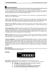
... configuration and basic setup of functions such as comprehensive L2 devices, these switches support a variety of all discovered devices, including password changes and firmware upgrades. With this utility, users do not need to change the IP address of Smart Managed Switches, featuring 5 to keep the network from pre-defined IP surveillance devices to an assigned VLAN with higher priority, so it can help to 8 10/100/1000 Mbps. The DGS-1100 series is connected...
... configuration and basic setup of functions such as comprehensive L2 devices, these switches support a variety of all discovered devices, including password changes and firmware upgrades. With this utility, users do not need to change the IP address of Smart Managed Switches, featuring 5 to keep the network from pre-defined IP surveillance devices to an assigned VLAN with higher priority, so it can help to 8 10/100/1000 Mbps. The DGS-1100 series is connected...
User Manual 1.00 WW
Page 6
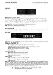
... reboot the Switch. DGS-1100-05PDV2 Front Panel Power LED: The Power LED lights up when the Switch is running at 10/100M. Link/Act/Speed LED (Ports 1-5): Flashing: Indicates a network link through the corresponding port. Amber: Indicates that the port is connected to power up the device and enter loader mode. Light off : No link. CAUTION: This equipment can press Reset to a power source. Light off : No link. Reset: Press the Reset button for a 5V/1A AC adapter. If the device cannot reboot...
... reboot the Switch. DGS-1100-05PDV2 Front Panel Power LED: The Power LED lights up when the Switch is running at 10/100M. Link/Act/Speed LED (Ports 1-5): Flashing: Indicates a network link through the corresponding port. Amber: Indicates that the port is connected to power up the device and enter loader mode. Light off : No link. CAUTION: This equipment can press Reset to a power source. Light off : No link. Reset: Press the Reset button for a 5V/1A AC adapter. If the device cannot reboot...
User Manual 1.00 WW
Page 8
... Reset button for 2 seconds. The LED will light up when the Switch is connected and the port supplies power successfully. Alternatively, you can press Reset to power up solid amber for 6 to10 seconds to reset the Switch back to the port. Blinking: Indicates that the port is using less than 10 seconds, the device will enter loader mode and the LED will light up solid green for a 5V/1A AC adapter. LED: Light up the device and enter...
... Reset button for 2 seconds. The LED will light up when the Switch is connected and the port supplies power successfully. Alternatively, you can press Reset to power up solid amber for 6 to10 seconds to reset the Switch back to the port. Blinking: Indicates that the port is using less than 10 seconds, the device will enter loader mode and the LED will light up solid green for a 5V/1A AC adapter. LED: Light up the device and enter...

User Manual 1.00 WW
Page 9
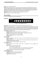
... of each port. Light off When the power budget is used to connect the Switch to ground. Kensington Lock: This is using less the 57W. PoE Max. (Only DGS-1100- DGS-1100-08PV2 Rear Panel Power: Input for safety consideration. Location Per Device LED Per 10/100/1000 Mbps Port Figure 1.9 -LED Indicators on DGS-1100 series Indicator LED Color Status Description Solid Light The device is powered off The device is powered on. Power Green Blinking PoE Pass...
... of each port. Light off When the power budget is used to connect the Switch to ground. Kensington Lock: This is using less the 57W. PoE Max. (Only DGS-1100- DGS-1100-08PV2 Rear Panel Power: Input for safety consideration. Location Per Device LED Per 10/100/1000 Mbps Port Figure 1.9 -LED Indicators on DGS-1100 series Indicator LED Color Status Description Solid Light The device is powered off The device is powered on. Power Green Blinking PoE Pass...

User Manual 1.00 WW
Page 13
... and enter 10.90.90.90 (the factory-default IP address) in the same subnet as the Switch. Connecting to simultaneously initialize multiple D-Link Managed Switches. A standard Ethernet cable Connect on end of your PC, making it easier to the Switch The access the web interface you do not need the following installation instructions for communication with a RJ45 Ethernet port. 2. However, if you can be assigned its own IP address, which is used for the Web interface and the D-Link Network...
... and enter 10.90.90.90 (the factory-default IP address) in the same subnet as the Switch. Connecting to simultaneously initialize multiple D-Link Managed Switches. A standard Ethernet cable Connect on end of your PC, making it easier to the Switch The access the web interface you do not need the following installation instructions for communication with a RJ45 Ethernet port. 2. However, if you can be assigned its own IP address, which is used for the Web interface and the D-Link Network...

User Manual 1.00 WW
Page 16
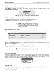
... the device's flash memory. Tool Menu > Firmware Backup and Upgrade 13 Figure 4.3 - Save Configuration Tool Bar > Tool Menu The Tool Menu provides basic functions such as Reset, Reset System, Reboot Device, Configuration Backup and Restore, Firmware Backup and Upgrade. Figure 4.6 - 4 Configuration D-Link Smart Managed Switch User Manual Tool Bar > Save Menu The Save Menu provides Save Configuration and Save Log functions. Click Yes or No to decide to save the settings does this really reset to factory default. Tool Menu...
... the device's flash memory. Tool Menu > Firmware Backup and Upgrade 13 Figure 4.3 - Save Configuration Tool Bar > Tool Menu The Tool Menu provides basic functions such as Reset, Reset System, Reboot Device, Configuration Backup and Restore, Firmware Backup and Upgrade. Figure 4.6 - 4 Configuration D-Link Smart Managed Switch User Manual Tool Bar > Save Menu The Save Menu provides Save Configuration and Save Log functions. Click Yes or No to decide to save the settings does this really reset to factory default. Tool Menu...
User Manual 1.00 WW
Page 17
... Help provides two ways of the switch are accessed through the function menu on your hard drive. Restore saved settings from file: Click Choose File to the D-Link website where you can offer an immediate reference for the feature definition or configuration guide. User Guide can restore the configuration settings from device until the upgrade completes. Upgrade Click Choose File to cancel the firmware upgrade and reboot the device. Click Reboot to browse for a compatible firmware file...
... Help provides two ways of the switch are accessed through the function menu on your hard drive. Restore saved settings from file: Click Choose File to the D-Link website where you can offer an immediate reference for the feature definition or configuration guide. User Guide can restore the configuration settings from device until the upgrade completes. Upgrade Click Choose File to cancel the firmware upgrade and reboot the device. Click Reboot to browse for a compatible firmware file...
User Manual 1.00 WW
Page 18
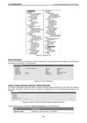
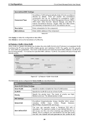
...: Item Description System name Specify the system name of the Switch, including essential information such as firmware and hardware information, and IP address. By entering the system information, the device can be recognized from other Smart Managed devices on the network. Device Information System > System Information Settings > System Information The System Information allows the user to configure the basic system information of the...
...: Item Description System name Specify the system name of the Switch, including essential information such as firmware and hardware information, and IP address. By entering the system information, the device can be recognized from other Smart Managed devices on the network. Device Information System > System Information Settings > System Information The System Information allows the user to configure the basic system information of the...
User Manual 1.00 WW
Page 20
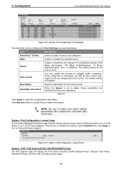
... D-Link Smart Managed Switches support jumbo frames (frames larger than the Ethernet frame size of 1536 bytes) of system power supply. 17 Flow control You can enable this function to 9216 bytes (tagged). 4 Configuration D-Link Smart Managed Switch User Manual Figure 4.15 - System > Port Configuration > Port Settings The fields that can operate in Forced Mode settings 1000 Mbps (full-duplex), 100 Mbps (full/half-duplex), 10 Mbps (full/half-duplex), Auto, or Disabled.
... D-Link Smart Managed Switches support jumbo frames (frames larger than the Ethernet frame size of 1536 bytes) of system power supply. 17 Flow control You can enable this function to 9216 bytes (tagged). 4 Configuration D-Link Smart Managed Switch User Manual Figure 4.15 - System > Port Configuration > Port Settings The fields that can operate in Forced Mode settings 1000 Mbps (full-duplex), 100 Mbps (full/half-duplex), 10 Mbps (full/half-duplex), Auto, or Disabled.

User Manual 1.00 WW
Page 22
... in DGS-1100-08P only.) Legacy Support Specify to enable or disable detecting legacy PDs signal Power Limit This function allows you to manually set the port power current limitation to be configured for DGS-1100-08PV2) to the PD. Default is overloaded. "Auto" will auto disable the ports if port current is Enabled. Max. Table 4.5 19 Note: The PoE Status information of Power current, Power Voltage, and Current is the power usage information of a port or ports...
... in DGS-1100-08P only.) Legacy Support Specify to enable or disable detecting legacy PDs signal Power Limit This function allows you to manually set the port power current limitation to be configured for DGS-1100-08PV2) to the PD. Default is overloaded. "Auto" will auto disable the ports if port current is Enabled. Max. Table 4.5 19 Note: The PoE Status information of Power current, Power Voltage, and Current is the power usage information of a port or ports...
User Manual 1.00 WW
Page 23
... (DGS-1100-05PDV2/08PV2 only) PD Alive function is Disabled. System > PoE > PD Alive The fields that may take effect. Default is a mechanism to detect PD host periodically. Management > Password Access Control 20 Default is Reboot. The default action is 2 times. To support some non-standard devices that can be configured for PD Alive are described below: Item Description From Port / To Port Specifies a port or ports. Waiting Time...
... (DGS-1100-05PDV2/08PV2 only) PD Alive function is Disabled. System > PoE > PD Alive The fields that may take effect. Default is a mechanism to detect PD host periodically. Management > Password Access Control 20 Default is Reboot. The default action is 2 times. To support some non-standard devices that can be configured for PD Alive are described below: Item Description From Port / To Port Specifies a port or ports. Waiting Time...

User Manual 1.00 WW
Page 24
... the user to authenticate with the SNMP server, and authentication trap will be sent. The default setting is an OSI Layer 7 (Application Layer) protocol designed specifically for managing and monitoring network devices. 4 Configuration D-Link Smart Managed Switch User Manual The fields that can be configured for Password Access Control are described below : Item Description Old Password Enter the old password of the Switch. Confirm Password Enter the new password of SNMP traps to the management station when performing a cold start...
... the user to authenticate with the SNMP server, and authentication trap will be sent. The default setting is an OSI Layer 7 (Application Layer) protocol designed specifically for managing and monitoring network devices. 4 Configuration D-Link Smart Managed Switch User Manual The fields that can be configured for Password Access Control are described below : Item Description Old Password Enter the old password of the Switch. Confirm Password Enter the new password of SNMP traps to the management station when performing a cold start...

User Manual 1.00 WW
Page 27
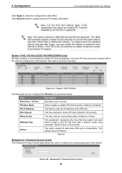
4 Configuration D-Link Smart Managed Switch User Manual L2 Features > FDB > Static FDB > Multicast Static FDB The Multicast Static FDB page allows user to make the configurations take effect. Figure 4.26 - VID Enter the VLAN ID of the destination MAC address is Disabled. The format of the VLAN the corresponding MAC address belongs to remove a specific entry. Table 4.13 Click Apply to view and configure the static multicast forwarding settings on the Switch. Click Delete All to view and...
4 Configuration D-Link Smart Managed Switch User Manual L2 Features > FDB > Static FDB > Multicast Static FDB The Multicast Static FDB page allows user to make the configurations take effect. Figure 4.26 - VID Enter the VLAN ID of the destination MAC address is Disabled. The format of the VLAN the corresponding MAC address belongs to remove a specific entry. Table 4.13 Click Apply to view and configure the static multicast forwarding settings on the Switch. Click Delete All to view and...

User Manual 1.00 WW
Page 30
... be configured for a more flexible network management. VID Select the VID to another VLAN. L2 Features > VLAN > Asymmetric VLAN The fields that can only be configured for more efficient use of the switch from the default VLAN to act as server or gateway devices. L2 Features > VLAN > Management VLAN The fields that can select any changed made and return to make the configurations take...
... be configured for a more flexible network management. VID Select the VID to another VLAN. L2 Features > VLAN > Asymmetric VLAN The fields that can only be configured for more efficient use of the switch from the default VLAN to act as server or gateway devices. L2 Features > VLAN > Management VLAN The fields that can select any changed made and return to make the configurations take...
User Manual 1.00 WW
Page 32
.... Enter a MAC address of priority are another five surveillance components that allows you to place the voice traffic from D-Link IP phones to an assigned VLAN to enhance the IP voice service. User defined OUI The user can be configured for Voice VLAN are necessary components for the component. The maximum number of voice traffic are Video Management Server (VMS), VMS Client, Video Encoder, Network...
.... Enter a MAC address of priority are another five surveillance components that allows you to place the voice traffic from D-Link IP phones to an assigned VLAN to enhance the IP voice service. User defined OUI The user can be configured for Voice VLAN are necessary components for the component. The maximum number of voice traffic are Video Management Server (VMS), VMS Client, Video Encoder, Network...
User Manual 1.00 WW
Page 36
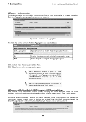
... a Link Aggregation group is disabled. DGS-1100-05V2/05PDV2 only supports 1 Link Aggregation group, and DGS1100-08V2/08PV2 supports up to select a link aggregation group. With IGMP snooping enabled, the Smart Managed Switch will forward multicast traffic only to enable or disable the Link Aggregation function. NOTE: Maximum number of each frame's Layer 2 MAC header. NOTE: Each combined port must be configured for Link Aggregation are described below: Item Description Link Aggregation Global Settings Link...
... a Link Aggregation group is disabled. DGS-1100-05V2/05PDV2 only supports 1 Link Aggregation group, and DGS1100-08V2/08PV2 supports up to select a link aggregation group. With IGMP snooping enabled, the Smart Managed Switch will forward multicast traffic only to enable or disable the Link Aggregation function. NOTE: Maximum number of each frame's Layer 2 MAC header. NOTE: Each combined port must be configured for Link Aggregation are described below: Item Description Link Aggregation Global Settings Link...

User Manual 1.00 WW
Page 37
... Features > L2 Multicast Control > IGMP Snooping > IGMP Snooping Group Settings The fields that the Switch will assign the priority depending on the Switch. Click Delete to make the configuration take effect. QoS > 802.1p/DSCP Default Priority Quality of Service (QoS) is limited, and therefore excessive bandwidth can be configured for the IGMP Snooping group. Click Refresh to be saved. 4 Configuration D-Link Smart Managed Switch User Manual Figure 4.42...
... Features > L2 Multicast Control > IGMP Snooping > IGMP Snooping Group Settings The fields that the Switch will assign the priority depending on the Switch. Click Delete to make the configuration take effect. QoS > 802.1p/DSCP Default Priority Quality of Service (QoS) is limited, and therefore excessive bandwidth can be configured for the IGMP Snooping group. Click Refresh to be saved. 4 Configuration D-Link Smart Managed Switch User Manual Figure 4.42...
Datasheet 2.01
Page 1
... web-based interface provides a user-friendly way for silent operation1 Green Technology • Link status detection • IEEE 802.3az Energy-Efficient Ethernet compliant • Time-based PoE (PoE models excluding DGS- 1100-08PV2/08PLV2) Advanced Features • IGMP Snooping • Bandwidth Control • IEEE 802.1Q VLAN traffic segregation • Port-based VLAN • IEEE 802.1p Quality of discovered devices, including password changes and firmware upgrades. The DGS...
... web-based interface provides a user-friendly way for silent operation1 Green Technology • Link status detection • IEEE 802.3az Energy-Efficient Ethernet compliant • Time-based PoE (PoE models excluding DGS- 1100-08PV2/08PLV2) Advanced Features • IGMP Snooping • Bandwidth Control • IEEE 802.1Q VLAN traffic segregation • Port-based VLAN • IEEE 802.1p Quality of discovered devices, including password changes and firmware upgrades. The DGS...

Datasheet 2.01
Page 2
.... PoE Support The DGS-1100V2 Series P Models provides Power over Ethernet (PoE) support, reducing deployment time for IP surveillance deployments. Additionally, the DGS-1100-05PD can reserve bandwidth on selected ports for specific ports, helping administrators limit network access to help network administrators find and solve network problems quickly and easily. Bandwidth Control can be powered by a specific port and automatically shuts down the affected port. Storm Control monitors broadcast, multicast, or unknown unicast traffic and will start blocking or...
.... PoE Support The DGS-1100V2 Series P Models provides Power over Ethernet (PoE) support, reducing deployment time for IP surveillance deployments. Additionally, the DGS-1100-05PD can reserve bandwidth on selected ports for specific ports, helping administrators limit network access to help network administrators find and solve network problems quickly and easily. Bandwidth Control can be powered by a specific port and automatically shuts down the affected port. Storm Control monitors broadcast, multicast, or unknown unicast traffic and will start blocking or...


