User Manual 1.00 WW
Page 2
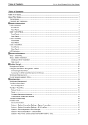
Table of Contents D-Link Smart Managed Switch User Manual Table of Contents Table of Contents ...i About This Guide ...1 Terms/Usage...1 Copyright and Trademarks ...1 1 Product Introduction ...2 DGS-1100-05V2...2 Front Panel ...2 Rear Panel...3 DGS-1100-05PDV2...3 Front Panel ...3 Rear Panel...4 DGS-1100-08V2...4 Front Panel ...4 Rear Panel...4 DGS-1100-08PV2 ...5 Front Panel ...5 Rear Panel...6 LED Indicators...6 2 Hardware Installation ...8 Step 1: Unpacking ...8 Step...
Table of Contents D-Link Smart Managed Switch User Manual Table of Contents Table of Contents ...i About This Guide ...1 Terms/Usage...1 Copyright and Trademarks ...1 1 Product Introduction ...2 DGS-1100-05V2...2 Front Panel ...2 Rear Panel...3 DGS-1100-05PDV2...3 Front Panel ...3 Rear Panel...4 DGS-1100-08V2...4 Front Panel ...4 Rear Panel...4 DGS-1100-08PV2 ...5 Front Panel ...5 Rear Panel...6 LED Indicators...6 2 Hardware Installation ...8 Step 1: Unpacking ...8 Step...
User Manual 1.00 WW
Page 3
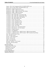
... Configuration (DGS-1100-05PDV2/08PV2 only 18 System > PoE > PD Alive (DGS-1100-05PDV2/08PV2 only 20 Management > Password Access Control 20 Management > SNMP > SNMP Global Settings 21 Management > SNMP > SNMP Community Table Settings 22 Management > SNMP > SNMP Host Settings 22 Management > D-Link Discovery Protocol...> STP Global Settings 30 L2 Features > Spanning Tree > STP Port Settings 31 L2 Features > Loopback Detection ...32 L2 Features > Link Aggregation ...33 L2 Features > L2 Multicast Control > IGMP Snooping > IGMP Snooping Settings 33 L2 Features > L2 Multicast Control > IGMP ...
... Configuration (DGS-1100-05PDV2/08PV2 only 18 System > PoE > PD Alive (DGS-1100-05PDV2/08PV2 only 20 Management > Password Access Control 20 Management > SNMP > SNMP Global Settings 21 Management > SNMP > SNMP Community Table Settings 22 Management > SNMP > SNMP Host Settings 22 Management > D-Link Discovery Protocol...> STP Global Settings 30 L2 Features > Spanning Tree > STP Port Settings 31 L2 Features > Loopback Detection ...32 L2 Features > Link Aggregation ...33 L2 Features > L2 Multicast Control > IGMP Snooping > IGMP Snooping Settings 33 L2 Features > L2 Multicast Control > IGMP ...

User Manual 1.00 WW
Page 4
...used in trademarks and trade names other Ethernet switches. Microsoft and Windows are trademarks of the device. About This Guide D-Link Smart Managed Switch User Manual About This Guide This guide provides step-by -step hardware installation procedures. 2. This guide is... names or their products. D-Link Corporation disclaims any manner whatsoever without notice. © 2020 D-Link Corporation. Hardware Installation: Step-by -step instructions on how install the D-Link DGS-110005V2/05PDV2/08V2/08PV2 Smart Managed Switches, how to use of D-Link Corporation; Getting Started: A...
...used in trademarks and trade names other Ethernet switches. Microsoft and Windows are trademarks of the device. About This Guide D-Link Smart Managed Switch User Manual About This Guide This guide provides step-by -step hardware installation procedures. 2. This guide is... names or their products. D-Link Corporation disclaims any manner whatsoever without notice. © 2020 D-Link Corporation. Hardware Installation: Step-by -step instructions on how install the D-Link DGS-110005V2/05PDV2/08V2/08PV2 Smart Managed Switches, how to use of D-Link Corporation; Getting Started: A...
User Manual 1.00 WW
Page 5
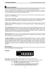
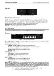
... devices to an assigned VLAN with easy-to the port level. D-Link's next generation Smart Managed switch series blends plug-and-play simplicity with earthing connection. The DGS-1100 Series features D-Link Green Technology which helps conserve power without sacrificing operational performance. With this.... Network Security. This allows for simultaneous configuration and basic setup of security to remotely control their PC. DGS-1100-05V2 5-Port 10/100/1000Mbps Smart Managed Switch. Link/Act/Speed LED (Ports 1-5): 10/100/1000 Mbps ports to connect Ethernet devices to a power source...
... devices to an assigned VLAN with easy-to the port level. D-Link's next generation Smart Managed switch series blends plug-and-play simplicity with earthing connection. The DGS-1100 Series features D-Link Green Technology which helps conserve power without sacrificing operational performance. With this.... Network Security. This allows for simultaneous configuration and basic setup of security to remotely control their PC. DGS-1100-05V2 5-Port 10/100/1000Mbps Smart Managed Switch. Link/Act/Speed LED (Ports 1-5): 10/100/1000 Mbps ports to connect Ethernet devices to a power source...
User Manual 1.00 WW
Page 6
...it will automatically enter loader mode. DGS-1100-05PDV2 2-Port 10/100/1000Mbps PoE and 3-Port 10/100/1000Mbps with 1 PD port Smart Managed Switch. DGS-1100-05V2 Rear Panel Power: Input for 6 to10 seconds to reset the Switch back to the default settings. Link/Act/Speed LED (Ports 1-5): ...Flashing: Indicates a network link through the corresponding port. If the device cannot reboot, it...
...it will automatically enter loader mode. DGS-1100-05PDV2 2-Port 10/100/1000Mbps PoE and 3-Port 10/100/1000Mbps with 1 PD port Smart Managed Switch. DGS-1100-05V2 Rear Panel Power: Input for 6 to10 seconds to reset the Switch back to the default settings. Link/Act/Speed LED (Ports 1-5): ...Flashing: Indicates a network link through the corresponding port. If the device cannot reboot, it...
User Manual 1.00 WW
Page 8
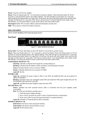
... the user unplugged certain PDs and made the PoE power budget left over 57W. Light off : No PD device insert. 5 Light off : No link. The LED will light up solid amber for 2 seconds. When pressing the Reset button for longer than 10 seconds, the device will enter loader mode...device and enter loader mode. Kensington Lock: This is over 7W, the PoE MAX LED will automatically enter loader mode. DGS-1100-08PV2 8-Port 10/100/1000Mbps PoE Smart Managed Switch. DGS-1100-08PV2 Front Panel Power LED: The Power LED lights up : Indicates the power output to the default settings. Press ...
... the user unplugged certain PDs and made the PoE power budget left over 57W. Light off : No PD device insert. 5 Light off : No link. The LED will light up solid amber for 2 seconds. When pressing the Reset button for longer than 10 seconds, the device will enter loader mode...device and enter loader mode. Kensington Lock: This is over 7W, the PoE MAX LED will automatically enter loader mode. DGS-1100-08PV2 8-Port 10/100/1000Mbps PoE Smart Managed Switch. DGS-1100-08PV2 Front Panel Power LED: The Power LED lights up : Indicates the power output to the default settings. Press ...

User Manual 1.00 WW
Page 9
... The Switches feature LED indicators for Power and Link/Act for DGS-1100-08P. If the user unplugged certain PDs and made the PoE power budget left over 57W. NOTE: The power budget is used to connect the Switch to ground. PoE Max. (Only DGS-1100- No additional PDs can be connected to a.../08V2/08PV2 switches along with earthing connection. Location Per Device LED Per 10/100/1000 Mbps Port Figure 1.9 -LED Indicators on DGS-1100 series Indicator LED Color Status Description Solid Light The device is using less the 57W. Red 08PV2) Solid Light Blinking When the power...
... The Switches feature LED indicators for Power and Link/Act for DGS-1100-08P. If the user unplugged certain PDs and made the PoE power budget left over 57W. NOTE: The power budget is used to connect the Switch to ground. PoE Max. (Only DGS-1100- No additional PDs can be connected to a.../08V2/08PV2 switches along with earthing connection. Location Per Device LED Per 10/100/1000 Mbps Port Figure 1.9 -LED Indicators on DGS-1100 series Indicator LED Color Status Description Solid Light The device is using less the 57W. Red 08PV2) Solid Light Blinking When the power...

User Manual 1.00 WW
Page 10
... error provide power to PD due to or power budget is being processed on this port. 1 Product Introduction D-Link Smart Managed Switch User Manual LED Per PoE Port PoE Status LED Per PD Port (DGS-1100- Light off Indicates there is a 10/100 Mbps connection on this port at 10/100 Mbps. Solid.... Solid Green PD device insert and power feeding. Light off No PD device inserts. PD Status 05PDV2 only) Solid Amber Indicates there is no active link on this port.
... error provide power to PD due to or power budget is being processed on this port. 1 Product Introduction D-Link Smart Managed Switch User Manual LED Per PoE Port PoE Status LED Per PD Port (DGS-1100- Light off Indicates there is a 10/100 Mbps connection on this port at 10/100 Mbps. Solid.... Solid Green PD device insert and power feeding. Light off No PD device inserts. PD Status 05PDV2 only) Solid Amber Indicates there is no active link on this port.

User Manual 1.00 WW
Page 11
... switches come with the keyholes on a wall. Figure 2.1 - Two mounting slots are present and undamaged. One DGS-1100-05V2/05PDV2/08V2/08PV2 Smart Managed Switch One AC external power adapter Four rubber feet Wall-mount kit Quick Installation Guide...bottom Wall-mount The Switch can be mounted on the back of the Switch. 2 Hardware Installation D-Link Smart Managed Switch User Manual 2 Hardware Installation This chapter provides unpacking and installation information for your D-Link DGS-110005V2/05PDV2/08V2/08PV2 Smart Managed Switch. Step 2: Drive the included screws into a wood wall...
... switches come with the keyholes on a wall. Figure 2.1 - Two mounting slots are present and undamaged. One DGS-1100-05V2/05PDV2/08V2/08PV2 Smart Managed Switch One AC external power adapter Four rubber feet Wall-mount kit Quick Installation Guide...bottom Wall-mount The Switch can be mounted on the back of the Switch. 2 Hardware Installation D-Link Smart Managed Switch User Manual 2 Hardware Installation This chapter provides unpacking and installation information for your D-Link DGS-110005V2/05PDV2/08V2/08PV2 Smart Managed Switch. Step 2: Drive the included screws into a wood wall...

User Manual 1.00 WW
Page 12
longueur 16 mm, nombre de vis *2) pour DGS-1100-05V2/05PDV2/08V2/08PV2 9 Length 16 mm, Number of the Switch onto the screws to secure the device to the wall. 2 Hardware Installation D-Link Smart Managed Switch User Manual Step 2. Hook the mounting keyholes on the back of screws *2) for DGS-1100-05V2/05PDV2/08V2/08PV2 Vis métallique (type M7 ; Wall mount installation Metal screw (M7 type; Figure 2.2 -
longueur 16 mm, nombre de vis *2) pour DGS-1100-05V2/05PDV2/08V2/08PV2 9 Length 16 mm, Number of the Switch onto the screws to secure the device to the wall. 2 Hardware Installation D-Link Smart Managed Switch User Manual Step 2. Hook the mounting keyholes on the back of screws *2) for DGS-1100-05V2/05PDV2/08V2/08PV2 Vis métallique (type M7 ; Wall mount installation Metal screw (M7 type; Figure 2.2 -

User Manual 1.00 WW
Page 13
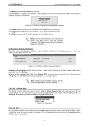
... Interface After successfully installing the Switch, you want to the Ethernet port on the PC. By using the web-based management interface, or the D-Link Network Assistant (DNA). Figure 3.1 - For example, if the Switch has an IP address of 10.90.90.90, the PC should have ... on the front panel of the Switch and connect the other end of Ethernet cable to manage multiple D-Link Smart Managed Switches, the D-Link Network Assistant (DNA) is used for the Web interface and the D-Link Network Assistant (DNA). Each switch must have an IP address of 10.x.y.z (where x/y is a number ...
... Interface After successfully installing the Switch, you want to the Ethernet port on the PC. By using the web-based management interface, or the D-Link Network Assistant (DNA). Figure 3.1 - For example, if the Switch has an IP address of 10.90.90.90, the PC should have ... on the front panel of the Switch and connect the other end of Ethernet cable to manage multiple D-Link Smart Managed Switches, the D-Link Network Assistant (DNA) is used for the Web interface and the D-Link Network Assistant (DNA). Each switch must have an IP address of 10.x.y.z (where x/y is a number ...

User Manual 1.00 WW
Page 14
... the upper-right corner of the window to start DNA. (Option 2) Click the 'Apps' icon in the upper-left corner of 0.0.0.0. 3 Getting Started D-Link Smart Managed Switch User Manual Figure 3.2 -Enter the IP address 10.90.90.90 in the web browser NOTE: The Switch's factory default IP address... is used to install the D-Link Network Assistant in Chrome. 4. When prompted to log in your PC. Figure 3.3 - D-LINK Network Assistant 2. You can download the DNA App from the Chrome web store and install it in a Chrome...
... the upper-right corner of the window to start DNA. (Option 2) Click the 'Apps' icon in the upper-left corner of 0.0.0.0. 3 Getting Started D-Link Smart Managed Switch User Manual Figure 3.2 -Enter the IP address 10.90.90.90 in the web browser NOTE: The Switch's factory default IP address... is used to install the D-Link Network Assistant in Chrome. 4. When prompted to log in your PC. Figure 3.3 - D-LINK Network Assistant 2. You can download the DNA App from the Chrome web store and install it in a Chrome...

User Manual 1.00 WW
Page 15
... can be seen as firmware upgrades and basic settings. The main configuration screen will be occupied. Click this to the local D-Link website. 12 4 Configuration D-Link Smart Managed Switch User Manual 4 Configuration The features and functions of the function tree. Under the username is the Logout button.... By clicking on the D-Link logo in the function tree will display all the settings of the screen the username and current IP address will show the current status...
... can be seen as firmware upgrades and basic settings. The main configuration screen will be occupied. Click this to the local D-Link website. 12 4 Configuration D-Link Smart Managed Switch User Manual 4 Configuration The features and functions of the function tree. Under the username is the Logout button.... By clicking on the D-Link logo in the function tree will display all the settings of the screen the username and current IP address will show the current status...

User Manual 1.00 WW
Page 16
... changes. Figure 4.3 - Figure 4.6 - Figure 4.7 - Figure 4.4 - Figure 4.5 - Click Yes or No to decide to save the settings does this really reset to restart the switch. 4 Configuration D-Link Smart Managed Switch User Manual Tool Bar > Save Menu The Save Menu provides Save Configuration and Save Log functions. Firmware Backup and Upgrade This functions...
... changes. Figure 4.3 - Figure 4.6 - Figure 4.7 - Figure 4.4 - Figure 4.5 - Click Yes or No to decide to save the settings does this really reset to restart the switch. 4 Configuration D-Link Smart Managed Switch User Manual Tool Bar > Save Menu The Save Menu provides Save Configuration and Save Log functions. Firmware Backup and Upgrade This functions...
User Manual 1.00 WW
Page 17
...14 And click Restore to backup settings file you want to restore. Online Help Function Tree All configuration options of online support: D-Link Support Site will enter boot-loader mode and the following sections provide a more detailed description of the Switch with or without the ... User Guide can find online resources such as updated firmware images; Click on the setup item that you want to configure. 4 Configuration D-Link Smart Managed Switch User Manual Click Backup to save the firmware to your inventories for a saved backup settings file. Click Upgrade to update the...
...14 And click Restore to backup settings file you want to restore. Online Help Function Tree All configuration options of online support: D-Link Support Site will enter boot-loader mode and the following sections provide a more detailed description of the Switch with or without the ... User Guide can find online resources such as updated firmware images; Click on the setup item that you want to configure. 4 Configuration D-Link Smart Managed Switch User Manual Click Backup to save the firmware to your inventories for a saved backup settings file. Click Upgrade to update the...
User Manual 1.00 WW
Page 18
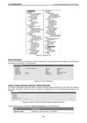
4 Configuration D-Link Smart Managed Switch User Manual Figure 4.11 -Function Tree Device Information The Device Information provides an overview of the Switch. 15 Figure 4.12 - System > System ...
4 Configuration D-Link Smart Managed Switch User Manual Figure 4.11 -Function Tree Device Information The Device Information provides an overview of the Switch. 15 Figure 4.12 - System > System ...

User Manual 1.00 WW
Page 19
... Timeout (60-36000) The Web Session Timeout controls the idle time-out period for the Switch to log into the web management interface again. 4 Configuration D-Link Smart Managed Switch User Manual System Location Specify the system location of the Switch. System > System Information Settings > IPv4 Interface The IPv4 Interface allows the...
... Timeout (60-36000) The Web Session Timeout controls the idle time-out period for the Switch to log into the web management interface again. 4 Configuration D-Link Smart Managed Switch User Manual System Location Specify the system location of the Switch. System > System Information Settings > IPv4 Interface The IPv4 Interface allows the...
User Manual 1.00 WW
Page 20
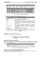
... > Port Configuration > Jumbo Frame D-Link Smart Managed Switches support jumbo frames (frames larger than the Ethernet frame size of 1536 bytes) of system power supply. 17 System > Port Configuration > Jumbo Frame System > PoE > PoE System (DGS-1100-05PDV2/08PV2 only) The PoE System page... will display the PoE status including System Budget Power, Support Total Power, Remainder Power, and the ratio of up to mitigate traffic congestion. 4 Configuration D-Link Smart Managed Switch User Manual Figure 4.15 ...
... > Port Configuration > Jumbo Frame D-Link Smart Managed Switches support jumbo frames (frames larger than the Ethernet frame size of 1536 bytes) of system power supply. 17 System > Port Configuration > Jumbo Frame System > PoE > PoE System (DGS-1100-05PDV2/08PV2 only) The PoE System page... will display the PoE status including System Budget Power, Support Total Power, Remainder Power, and the ratio of up to mitigate traffic congestion. 4 Configuration D-Link Smart Managed Switch User Manual Figure 4.15 ...
User Manual 1.00 WW
Page 21
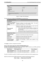
... that the PSE provides power according to a port once the threshold is between 7.1 and 64 Watts. PoE Output 30 Watts 64 Watts The DGS-1100-05PDV2 and DGS-1100-08PV2 work with the lower priority will be configured for DGS-110008PV2) Manually configure the system power budget. 4 Configuration D-Link Smart Managed Switch User Manual Figure 4.17 -
... that the PSE provides power according to a port once the threshold is between 7.1 and 64 Watts. PoE Output 30 Watts 64 Watts The DGS-1100-05PDV2 and DGS-1100-08PV2 work with the lower priority will be configured for DGS-110008PV2) Manually configure the system power budget. 4 Configuration D-Link Smart Managed Switch User Manual Figure 4.17 -

User Manual 1.00 WW
Page 22
4 Configuration D-Link Smart Managed Switch User Manual 0 Default 1 Optional 2 Optional 3 Optional 4 Optional 15.... / To Port to renew the information. Default is over 375mA in 802.3af mode or 625mA in DGS-1100-08P only.) Legacy Support Specify to enable or disable detecting legacy PDs signal Power Limit This function allows... you to manually set the port power current limitation to be configured for DGS-1100-08PV2) to 30000 milliwatts for PoE Configuration are described below: Item Description From Port / To Port Specifies ...
4 Configuration D-Link Smart Managed Switch User Manual 0 Default 1 Optional 2 Optional 3 Optional 4 Optional 15.... / To Port to renew the information. Default is over 375mA in 802.3af mode or 625mA in DGS-1100-08P only.) Legacy Support Specify to enable or disable detecting legacy PDs signal Power Limit This function allows... you to manually set the port power current limitation to be configured for DGS-1100-08PV2) to 30000 milliwatts for PoE Configuration are described below: Item Description From Port / To Port Specifies ...


