Handling swollen Lithium-ion batteries
Page 1
To prevent possible further damage to the device enclosure or internal components leading to malfunction, discontinue the use tools of any type to pry on battery power. Dell, EMC, and other computers with newer ultra-thin laptops) and long battery life. or its subsidiaries. We recommend contacting Dell product support for options to replace a swollen battery under the terms of swelling, do not try to...
To prevent possible further damage to the device enclosure or internal components leading to malfunction, discontinue the use tools of any type to pry on battery power. Dell, EMC, and other computers with newer ultra-thin laptops) and long battery life. or its subsidiaries. We recommend contacting Dell product support for options to replace a swollen battery under the terms of swelling, do not try to...

Service Manual
Page 9
... Removing the display back-cover and antenna assembly 104 Prerequisites 104 Procedure 105 Replacing the display back-cover and antenna assembly 106 Procedure 106 Post-requisites 106 Removing the camera 107 Prerequisites 107 Procedure 107 Replacing the camera 109 Post-requisites 109 Procedure 109 BIOS overview 110 Entering the BIOS setup program 110 Timing key sequences 110 System Setup Options 110 Clearing forgotten passwords 116 Clearing CMOS settings 116 Flashing the BIOS 117 Boot menu 117 Boot menu...
... Removing the display back-cover and antenna assembly 104 Prerequisites 104 Procedure 105 Replacing the display back-cover and antenna assembly 106 Procedure 106 Post-requisites 106 Removing the camera 107 Prerequisites 107 Procedure 107 Replacing the camera 109 Post-requisites 109 Procedure 109 BIOS overview 110 Entering the BIOS setup program 110 Timing key sequences 110 System Setup Options 110 Clearing forgotten passwords 116 Clearing CMOS settings 116 Flashing the BIOS 117 Boot menu 117 Boot menu...

Service Manual
Page 11
... working inside the computer, replace all attached network devices and peripherals, such as keyboard, mouse, and monitor from your computer. 5 Remove any media card and optical disc from their electrical outlets. 4 Disconnect all covers, panels, and screws before opening the computer cover or panels. WARNING: Disconnect all open files and exit all power sources before connecting to protect your computer from your computer depending on the configuration you are using a different operating...
... working inside the computer, replace all attached network devices and peripherals, such as keyboard, mouse, and monitor from your computer. 5 Remove any media card and optical disc from their electrical outlets. 4 Disconnect all covers, panels, and screws before opening the computer cover or panels. WARNING: Disconnect all open files and exit all power sources before connecting to protect your computer from your computer depending on the configuration you are using a different operating...

Service Manual
Page 15
After working inside your computer CAUTION: Leaving stray or loose screws inside your computer may severely damage your computer. 1 Replace all screws and ensure that no stray screws remain inside your computer. 2 Connect any external devices, peripherals, or cables you removed before working on your computer. 3 Replace any media cards, discs, or any other parts that you removed before working on your computer. 4 Connect your computer and all attached devices to their electrical outlets. 5 Turn on your computer. 15
After working inside your computer CAUTION: Leaving stray or loose screws inside your computer may severely damage your computer. 1 Replace all screws and ensure that no stray screws remain inside your computer. 2 Connect any external devices, peripherals, or cables you removed before working on your computer. 3 Replace any media cards, discs, or any other parts that you removed before working on your computer. 4 Connect your computer and all attached devices to their electrical outlets. 5 Turn on your computer. 15

Service Manual
Page 44
... that you note the BIOS setup program's settings before removing the coin-cell battery. It is recommended that secures the coin-cell battery cable to the system board. 3 Note the cable routing and remove the coin-cell battery cable from step 1 to default. Prerequisites 1 Remove the base cover. 2 Remove the wireless card. 3 Follow the procedure from the routing guide on the palm-rest assembly. 44 After working inside your computer...
... that you note the BIOS setup program's settings before removing the coin-cell battery. It is recommended that secures the coin-cell battery cable to the system board. 3 Note the cable routing and remove the coin-cell battery cable from step 1 to default. Prerequisites 1 Remove the base cover. 2 Remove the wireless card. 3 Follow the procedure from the routing guide on the palm-rest assembly. 44 After working inside your computer...

Service Manual
Page 54
Prerequisites 1 Remove the base cover. 2 Remove the wireless card. 3 Follow the procedure from step 1 to step 3 in "Removing the hard drive". 4 Remove the solid-state drive. 5 Remove the rear-I/O cover. 6 Remove the computer base. 7 Remove the battery. 8 Remove the memory modules. 9 Follow the procedure from step 1 to the palmrest assembly. 54 After working inside your computer, follow the steps in Before working inside your computer. For more safety best practices, see...
Prerequisites 1 Remove the base cover. 2 Remove the wireless card. 3 Follow the procedure from step 1 to step 3 in "Removing the hard drive". 4 Remove the solid-state drive. 5 Remove the rear-I/O cover. 6 Remove the computer base. 7 Remove the battery. 8 Remove the memory modules. 9 Follow the procedure from step 1 to the palmrest assembly. 54 After working inside your computer, follow the steps in Before working inside your computer. For more safety best practices, see...

Service Manual
Page 64
... "Removing the hard drive". 4 Remove the solid-state drive. 5 Remove the rear-I/O cover. 6 Remove the computer base. 7 Remove the battery. 8 Remove the memory modules. You must make the appropriate changes again after you have made to the BIOS using the BIOS setup program. You must enter the Service Tag in the BIOS setup program after you replace the system board. Removing the system board WARNING: Before working inside your computer, read the safety information that secures the display cable to...
... "Removing the hard drive". 4 Remove the solid-state drive. 5 Remove the rear-I/O cover. 6 Remove the computer base. 7 Remove the battery. 8 Remove the memory modules. You must make the appropriate changes again after you have made to the BIOS using the BIOS setup program. You must enter the Service Tag in the BIOS setup program after you replace the system board. Removing the system board WARNING: Before working inside your computer, read the safety information that secures the display cable to...

Service Manual
Page 69
... USB Type-C port bracket with the screw hole on the system board. 5 Replace the screw (M2.5x5) that secures the I/O-board cable to the I /O-board and close the latches to secure the cables. 9 Connect the power-adapter port cable and speaker cable to the system board. 69 You must make the appropriate changes again after you have made to the BIOS using the BIOS setup program. rest assembly. Replacing the system board WARNING: Before working...
... USB Type-C port bracket with the screw hole on the system board. 5 Replace the screw (M2.5x5) that secures the I/O-board cable to the I /O-board and close the latches to secure the cables. 9 Connect the power-adapter port cable and speaker cable to the system board. 69 You must make the appropriate changes again after you have made to the BIOS using the BIOS setup program. rest assembly. Replacing the system board WARNING: Before working...

Service Manual
Page 71
... in "Removing the hard drive". 4 Remove the solid-state drive. 5 Remove the rear-I/O cover. 6 Remove the computer base. 7 Remove the battery. 8 Remove the memory modules. 9 Follow the procedure from the system board. 71 WARNING: The heat sink may become hot during normal operation. Removing the heat-sink assembly WARNING: Before working inside your computer, read the safety information that secures the fan cable to the system board. 4 Disconnect the fan cable from step...
... in "Removing the hard drive". 4 Remove the solid-state drive. 5 Remove the rear-I/O cover. 6 Remove the computer base. 7 Remove the battery. 8 Remove the memory modules. 9 Follow the procedure from the system board. 71 WARNING: The heat sink may become hot during normal operation. Removing the heat-sink assembly WARNING: Before working inside your computer, read the safety information that secures the fan cable to the system board. 4 Disconnect the fan cable from step...

Service Manual
Page 82
... 1 Remove the base cover. 2 Remove the wireless card. 3 Remove the memory modules. 4 Follow the procedure from step 1 to step 3 in "Removing the hard drive". 5 Remove the solid-state drive. 6 Remove the rear-I/O cover. 7 Remove the computer base. 8 Remove the coin-cell battery. 9 Remove the battery. 10 Remove the touch pad. 11 Remove the I/O board. 12 Remove the speakers. 13 Follow the procedure from step 1 to step 17 in "Removing the system board". 14 Remove the keyboard. 15 Remove the power-adapter port. 16 Remove the power-button board . 82...
... 1 Remove the base cover. 2 Remove the wireless card. 3 Remove the memory modules. 4 Follow the procedure from step 1 to step 3 in "Removing the hard drive". 5 Remove the solid-state drive. 6 Remove the rear-I/O cover. 7 Remove the computer base. 8 Remove the coin-cell battery. 9 Remove the battery. 10 Remove the touch pad. 11 Remove the I/O board. 12 Remove the speakers. 13 Follow the procedure from step 1 to step 17 in "Removing the system board". 14 Remove the keyboard. 15 Remove the power-adapter port. 16 Remove the power-button board . 82...

Service Manual
Page 110
... installed devices, the items listed in BIOS setup program. To prevent the keyboard from locking, wait until the keyboard is locked out. System Setup Options NOTE: Depending on the screen to enter the BIOS setup program. In such cases, a keyboard error message is displayed on or restart your computer with the Ctrl+Alt+Del key combination. BIOS overview The BIOS manages data flow between the computer's operating system and attached devices such as the hard disk, video adapter, keyboard, mouse...
... installed devices, the items listed in BIOS setup program. To prevent the keyboard from locking, wait until the keyboard is locked out. System Setup Options NOTE: Depending on the screen to enter the BIOS setup program. In such cases, a keyboard error message is displayed on or restart your computer with the Ctrl+Alt+Del key combination. BIOS overview The BIOS manages data flow between the computer's operating system and attached devices such as the hard disk, video adapter, keyboard, mouse...

Service Manual
Page 112
... how the BIOS, in the absence of third SSD installed. Displays the type of primary SSD installed. Table 4. USB emulation is always enabled during POST. 112 Default: Enabled VT for Direct I/O Specify whether a Virtual Machine Monitor (VMM) can utilize the additional hardware capabilities provided by Intel Virtualization Technology for Direct I/O. Default: Enabled Virtualization Allows you to enable or disable the Intel Virtualization technology. System setup options-Advanced menu Advanced...
... how the BIOS, in the absence of third SSD installed. Displays the type of primary SSD installed. Table 4. USB emulation is always enabled during POST. 112 Default: Enabled VT for Direct I/O Specify whether a Virtual Machine Monitor (VMM) can utilize the additional hardware capabilities provided by Intel Virtualization Technology for Direct I/O. Default: Enabled Virtualization Allows you to enable or disable the Intel Virtualization technology. System setup options-Advanced menu Advanced...

Service Manual
Page 113
Default: Disabled Allows you to configure the operating mode of USB device (floppy, hard drive, or memory key) when this option is enabled, a device connected to set function key or multimedia key as the default function key behavior. Default: Enabled Allows you to charge USB devices when the computer is turned off . NOTE: If USB PowerShare is off or in standby mode. Default: Enabled Allows you use AC adapters that are not supported by your computer battery using Standard Charge or Express Charge mode. Default: AHCI Allows you to choose if the...
Default: Disabled Allows you to configure the operating mode of USB device (floppy, hard drive, or memory key) when this option is enabled, a device connected to set function key or multimedia key as the default function key behavior. Default: Enabled Allows you to charge USB devices when the computer is turned off . NOTE: If USB PowerShare is off or in standby mode. Default: Enabled Allows you use AC adapters that are not supported by your computer battery using Standard Charge or Express Charge mode. Default: AHCI Allows you to choose if the...

Service Manual
Page 115
... utility. Default: Permitted Enable or disable the BIOS module interface of the optional Computrace Service from Absolute Software. Table 6. Boot Option #1 Displays the available first boot option. 115 Security System Password HDD password Password Change Computrace Firmware TPM UEFI Capsule Firmware Updates controls access to the computer at boot. Allows you to set the system password. System setup options-Boot menu Boot Boot List Option Displays the available boot options. File Browser Add Boot Option Allows to delete the boot options Secure Boot Enable or disable...
... utility. Default: Permitted Enable or disable the BIOS module interface of the optional Computrace Service from Absolute Software. Table 6. Boot Option #1 Displays the available first boot option. 115 Security System Password HDD password Password Change Computrace Firmware TPM UEFI Capsule Firmware Updates controls access to the computer at boot. Allows you to set the system password. System setup options-Boot menu Boot Boot List Option Displays the available boot options. File Browser Add Boot Option Allows to delete the boot options Secure Boot Enable or disable...
Service Manual
Page 116
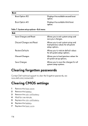
... changes. Clearing CMOS settings 1 Remove the base cover. 2 Remove the battery. 3 Remove the coin-cell battery. 4 Wait for all system setup options. Discard Changes Allows you to load previous values for all system setup options. System setup options-Exit menu Exit Save Changes and Reset Allows you to exit system setup and save the changes for one minute. 5 Replace the coin-cell battery. 6 Replace the battery. 7 Replace the base cover. 116 Table 7. Displays the available third boot option. Restore Defaults Allows you to restore default...
... changes. Clearing CMOS settings 1 Remove the base cover. 2 Remove the battery. 3 Remove the coin-cell battery. 4 Wait for all system setup options. Discard Changes Allows you to load previous values for all system setup options. System setup options-Exit menu Exit Save Changes and Reset Allows you to exit system setup and save the changes for one minute. 5 Replace the coin-cell battery. 6 Replace the battery. 7 Replace the base cover. 116 Table 7. Displays the available third boot option. Restore Defaults Allows you to restore default...

Service Manual
Page 117
... flash the BIOS: 1 Turn on your computer. 2 Go to www.dell.com/support. 3 Click Product support, enter the Service Tag of your computer. 8 After the download is prompted to use the auto-detect feature or manually browse for your computer model. 4 Click Drivers & downloads → Find it myself. 5 Select the operating system installed on the BIOS screen. • Diagnostics options - Boot menu enhancements The boot menu enhancements are as follows: • Easier access - The boot menu...
... flash the BIOS: 1 Turn on your computer. 2 Go to www.dell.com/support. 3 Click Product support, enter the Service Tag of your computer. 8 After the download is prompted to use the auto-detect feature or manually browse for your computer model. 4 Click Drivers & downloads → Find it myself. 5 Select the operating system installed on the BIOS screen. • Diagnostics options - Boot menu enhancements The boot menu enhancements are as follows: • Easier access - The boot menu...

Setup and Specifications
Page 4
... are using Alienware Graphics Amplifier with computers that are only shipped with your computer Connect the power adapter and press the power button. HTC Vive 1 Download and run the setup tools for your VR headset at www.dell.com/VRsupport. 2 Connect the HDMI cable of the HTC Vive headset to the back of your computer. 4 Follow the on-screen instructions to the USB 3.1 Gen 1 port at www.dell...
... are using Alienware Graphics Amplifier with computers that are only shipped with your computer Connect the power adapter and press the power button. HTC Vive 1 Download and run the setup tools for your VR headset at www.dell.com/VRsupport. 2 Connect the HDMI cable of the HTC Vive headset to the back of your computer. 4 Follow the on-screen instructions to the USB 3.1 Gen 1 port at www.dell...

Setup and Specifications
Page 11
... Alienware Graphics Amplifier to enhance the graphics performance. 6 Power-adapter port Connect a power adapter to provide power to 15 W power output that enables two-way power supply between devices. NOTE: A USB Type-C to a TV or another DisplayPort-in enabled device. Provides video and audio output. 3 HDMI port Connect to DisplayPort adapter (sold separately) is turned off . Left 1 Security-cable slot (for Thunderbolt 3. Provides video and audio output. 4 Thunderbolt 3 (USB Type-C) port Supports USB 3.1 Gen 2, DisplayPort 1.2, Thunderbolt 3 and also enables you to charge your USB...
... Alienware Graphics Amplifier to enhance the graphics performance. 6 Power-adapter port Connect a power adapter to provide power to 15 W power output that enables two-way power supply between devices. NOTE: A USB Type-C to a TV or another DisplayPort-in enabled device. Provides video and audio output. 3 HDMI port Connect to DisplayPort adapter (sold separately) is turned off . Left 1 Security-cable slot (for Thunderbolt 3. Provides video and audio output. 4 Thunderbolt 3 (USB Type-C) port Supports USB 3.1 Gen 2, DisplayPort 1.2, Thunderbolt 3 and also enables you to charge your USB...
Setup and Specifications
Page 15
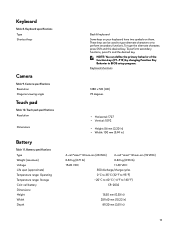
... 11.40 VDC 300 discharge/charge cycles 0°C to 35°C (32°F to 95°F) -20°C to 60°C (-4°F to perform secondary functions. Keyboard specifications Type Shortcut keys Camera Table 9. To type the alternate character, press Shift and the desired key. Camera specifications Resolution Diagonal viewing angle Touch pad Table 10. NOTE: You can be used to type alternate characters or to...
... 11.40 VDC 300 discharge/charge cycles 0°C to 35°C (32°F to 95°F) -20°C to 60°C (-4°F to perform secondary functions. Keyboard specifications Type Shortcut keys Camera Table 9. To type the alternate character, press Shift and the desired key. Camera specifications Resolution Diagonal viewing angle Touch pad Table 10. NOTE: You can be used to type alternate characters or to...

Setup and Specifications
Page 19
List of Macro keys Keys Description Disconnect Alienware Graphics Amplifier Disable/enable wireless Mute audio Decrease volume Increase volume Toggle integrated/discrete graphics Switch to external display Decrease brightness Increase brightness Disable/enable touch pad Disable/enable AlienFX Description Macro keys NOTE: You can configure modes and assign multiple tasks for the macro keys on the keyboard. 19 List of keyboard shortcuts Keys Table 18. Keyboard shortcuts Table 17.
List of Macro keys Keys Description Disconnect Alienware Graphics Amplifier Disable/enable wireless Mute audio Decrease volume Increase volume Toggle integrated/discrete graphics Switch to external display Decrease brightness Increase brightness Disable/enable touch pad Disable/enable AlienFX Description Macro keys NOTE: You can configure modes and assign multiple tasks for the macro keys on the keyboard. 19 List of keyboard shortcuts Keys Table 18. Keyboard shortcuts Table 17.


