
Service Manual
Page 8
Changing the audio settings 94 HDMI...94 Graphics...94 Downloading the graphics driver 94 Identifying the display adapter 95 Changing the screen resolution 95 Rotating the display 96 USB...98 Downloading the USB 2.0 and USB 3.0 driver 98 Enabling or disabling the USB in BIOS setup program 98 Fixing a no-boot issue caused by USB emulation 99 Wi-Fi...99 Turning on or off Wi-Fi 99 Downloading the Wi-Fi driver 99 Configuring the Wi-Fi 100 Bluetooth...100 Turning on...
Changing the audio settings 94 HDMI...94 Graphics...94 Downloading the graphics driver 94 Identifying the display adapter 95 Changing the screen resolution 95 Rotating the display 96 USB...98 Downloading the USB 2.0 and USB 3.0 driver 98 Enabling or disabling the USB in BIOS setup program 98 Fixing a no-boot issue caused by USB emulation 99 Wi-Fi...99 Turning on or off Wi-Fi 99 Downloading the Wi-Fi driver 99 Configuring the Wi-Fi 100 Bluetooth...100 Turning on...

Service Manual
Page 10
... page at www.dell.com/ regulatory_compliance. 10 Safety instructions Use the following safety guidelines to ground the system board. NOTE: If you ordered. Windows 10: Click Start → Power → Shut down . WARNING: Before working inside your computer, read the safety information that shipped with your computer. Console Mode: On the Home screen, click Power → Shut down . - NOTE: Remove the USB dongle from...
... page at www.dell.com/ regulatory_compliance. 10 Safety instructions Use the following safety guidelines to ground the system board. NOTE: If you ordered. Windows 10: Click Start → Power → Shut down . WARNING: Before working inside your computer, read the safety information that shipped with your computer. Console Mode: On the Home screen, click Power → Shut down . - NOTE: Remove the USB dongle from...

Service Manual
Page 12
After working inside your computer CAUTION: Leaving stray or loose screws inside your computer may severely damage your computer. 1 Replace all screws and ensure that no stray screws remain inside your computer. 2 Connect any external devices, peripherals, or cables you removed before working on your computer. 3 Replace any media cards, discs, or any other parts that you removed before working on your computer. 4 Connect your computer and all attached devices to their electrical outlets. 5 Turn on your computer. 12
After working inside your computer CAUTION: Leaving stray or loose screws inside your computer may severely damage your computer. 1 Replace all screws and ensure that no stray screws remain inside your computer. 2 Connect any external devices, peripherals, or cables you removed before working on your computer. 3 Replace any media cards, discs, or any other parts that you removed before working on your computer. 4 Connect your computer and all attached devices to their electrical outlets. 5 Turn on your computer. 12

Service Manual
Page 75
... at www.dell.com/ regulatory_compliance. Post-requisites 1 Replace the wireless card. 2 Replace the memory modules. 3 Replace the video-card fan. 4 Replace the processor. 5 Replace the processor heat sink. 75 board components". Replacing the system board WARNING: Before working inside your computer, read the safety information that secure the back panel to the chassis. 5 Connect the USB-port cable, front-panel light board cable, and power-button board cable to the BIOS using the BIOS setup program. NOTE: Your computer's Service Tag is stored in Before working inside your computer...
... at www.dell.com/ regulatory_compliance. Post-requisites 1 Replace the wireless card. 2 Replace the memory modules. 3 Replace the video-card fan. 4 Replace the processor. 5 Replace the processor heat sink. 75 board components". Replacing the system board WARNING: Before working inside your computer, read the safety information that secure the back panel to the chassis. 5 Connect the USB-port cable, front-panel light board cable, and power-button board cable to the BIOS using the BIOS setup program. NOTE: Your computer's Service Tag is stored in Before working inside your computer...

Service Manual
Page 81
... System Name System Time System Date Service Tag Service Tag Input Asset Tag Processor Information Processor Type Processor ID Processor Core Count Processor L1 Cache Processor L2 Cache Processor L3 Cache Memory Information Memory Installed Memory Available Memory Running Speed Memory Technology SATA Information SATA 1 Displays the BIOS version number. Displays the system name. Displays the BIOS release date. Displays the processor identification code. Displays the service tag of cores in the processor. Displays the processor L1 cache size. Displays the asset tag of your...
... System Name System Time System Date Service Tag Service Tag Input Asset Tag Processor Information Processor Type Processor ID Processor Core Count Processor L1 Cache Processor L2 Cache Processor L3 Cache Memory Information Memory Installed Memory Available Memory Running Speed Memory Technology SATA Information SATA 1 Displays the BIOS version number. Displays the system name. Displays the BIOS release date. Displays the processor identification code. Displays the service tag of cores in the processor. Displays the processor L1 cache size. Displays the asset tag of your...
Service Manual
Page 84
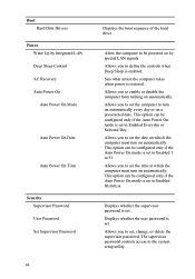
... option can be configured only if the Auto Power On mode is set . Displays whether the supervisor password is set to set, change, or delete the supervisor password. The supervisor password controls access to enable or disable the computer from turning on by Integrated LAN Deep Sleep Control AC Recovery Auto Power On Auto Power On Mode Auto Power On Date Auto Power On Time Security Supervisor Password User Password Set Supervisor Password 84 Displays the boot sequence of the hard drive. Boot Hard Disk Drivers Power Wake Up by special LAN...
... option can be configured only if the Auto Power On mode is set . Displays whether the supervisor password is set to set, change, or delete the supervisor password. The supervisor password controls access to enable or disable the computer from turning on by Integrated LAN Deep Sleep Control AC Recovery Auto Power On Auto Power On Mode Auto Power On Date Auto Power On Time Security Supervisor Password User Password Set Supervisor Password 84 Displays the boot sequence of the hard drive. Boot Hard Disk Drivers Power Wake Up by special LAN...

Service Manual
Page 86
... optical drive to run Dell Diagnostics from the Drivers and Utilities disc or to boot from the next bootable device. The Boot Options appears, listing all future boots, for the current boot 1 If you are the devices that your device is restored at the next boot. • Future Boot Sequence - Insert the memory device into a USB connector and restart the computer. The computer attempts to boot from and press Enter. If the computer cannot boot from the device...
... optical drive to run Dell Diagnostics from the Drivers and Utilities disc or to boot from the next bootable device. The Boot Options appears, listing all future boots, for the current boot 1 If you are the devices that your device is restored at the next boot. • Future Boot Sequence - Insert the memory device into a USB connector and restart the computer. The computer attempts to boot from and press Enter. If the computer cannot boot from the device...

Service Manual
Page 90
2 Remove the jumper plug from the password jumper (pin number three and four) and place it on the CMOS jumper (pin number five and six). 1 jumper plug 2 CMOS jumper (pin number five and six) 3 password jumper (pin number three and four) 3 Replace the video-card fan. 4 Replace the processor fan. 5 Replace the top cover. 6 Replace the base cover. 7 Turn on your computer. 90 A message is displayed to confirm that the CMOS settings are reset and default BIOS setup has been loaded. 8 Press F1 to continue and wait till the operating system is completely loaded. 9 Shut down your computer.
2 Remove the jumper plug from the password jumper (pin number three and four) and place it on the CMOS jumper (pin number five and six). 1 jumper plug 2 CMOS jumper (pin number five and six) 3 password jumper (pin number three and four) 3 Replace the video-card fan. 4 Replace the processor fan. 5 Replace the top cover. 6 Replace the base cover. 7 Turn on your computer. 90 A message is displayed to confirm that the CMOS settings are reset and default BIOS setup has been loaded. 8 Press F1 to continue and wait till the operating system is completely loaded. 9 Shut down your computer.
Service Manual
Page 93
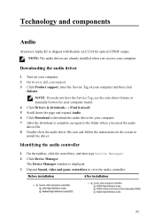
... expand Audio. 6 Click Download to download the audio driver for optical S/PDIF output. Identifying the audio controller 1 On the taskbar, click the search box, and then type Device Manager. 2 Click Device Manager. Technology and components Audio Alienware Alpha R2 is shipped with Realtek ALC3234 for your computer. 7 After the download is displayed. 3 Expand Sound, video and game controllers to view the audio controller. The Device Manager window is complete, navigate to www.dell.com/support. 3 Click Product support, enter the Service Tag...
... expand Audio. 6 Click Download to download the audio driver for optical S/PDIF output. Identifying the audio controller 1 On the taskbar, click the search box, and then type Device Manager. 2 Click Device Manager. Technology and components Audio Alienware Alpha R2 is shipped with Realtek ALC3234 for your computer. 7 After the download is displayed. 3 Expand Sound, video and game controllers to view the audio controller. The Device Manager window is complete, navigate to www.dell.com/support. 3 Click Product support, enter the Service Tag...
Service Manual
Page 94
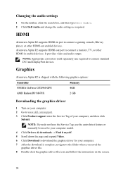
...-detect feature or manually browse for your computer model. 4 Click Drivers & downloads → Find it myself. 5 Scroll down the page and expand Video. 6 Click Download to download the graphics driver for your computer, and then click Submit. Alienware Alpha R2 supports HDMI-out port to connect a gaming console, Blu‑ray player, or other HDMI‑in enabled devices. HDMI Alienware Alpha R2 supports HDMI-in port to connect a monitor, TV, or other HDMI‑out enabled devices. Changing the audio settings 1 On the...
...-detect feature or manually browse for your computer model. 4 Click Drivers & downloads → Find it myself. 5 Scroll down the page and expand Video. 6 Click Download to download the graphics driver for your computer, and then click Submit. Alienware Alpha R2 supports HDMI-out port to connect a gaming console, Blu‑ray player, or other HDMI‑in enabled devices. HDMI Alienware Alpha R2 supports HDMI-in port to connect a monitor, TV, or other HDMI‑out enabled devices. Changing the audio settings 1 On the...
Service Manual
Page 98
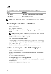
... Enabling or disabling the USB in Alienware Alpha R2. The BIOS setup program is displayed. 3 On the Advanced tab, select USB Configuration. 4 Select the Front USB Ports or Rear USB Ports options to be installed before it myself. 5 Scroll down the page and expand Chipset. 6 Click Download to download the USB 2.0 or USB 3.0 driver for your computer. 7 After the download is displayed on the screen to the folder where you do not have the Service Tag, use the...
... Enabling or disabling the USB in Alienware Alpha R2. The BIOS setup program is displayed. 3 On the Advanced tab, select USB Configuration. 4 Select the Front USB Ports or Rear USB Ports options to be installed before it myself. 5 Scroll down the page and expand Chipset. 6 Click Download to download the USB 2.0 or USB 3.0 driver for your computer. 7 After the download is displayed on the screen to the folder where you do not have the Service Tag, use the...
Service Manual
Page 99
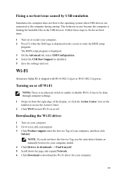
... Alienware Alpha R2 is no -boot issue: 1 Turn on or restart your computer. 99 It has to be done through computer settings. 1 Swipe-in the USB devices. Follow these steps to fix the no physical switch to download the Wi-Fi driver for bootable files in from the right edge of the display, or click the Action Center icon on the taskbar to access...
... Alienware Alpha R2 is no -boot issue: 1 Turn on or restart your computer. 99 It has to be done through computer settings. 1 Swipe-in the USB devices. Follow these steps to fix the no physical switch to download the Wi-Fi driver for bootable files in from the right edge of the display, or click the Action Center icon on the taskbar to access...
Service Manual
Page 105
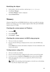
... system memory in Windows 1 Click Start . 2 Select Settings . 3 Click System → About. For more information, refer System setup options. NOTE: If the operating system logo appears, wait until you see the desktop. The Device Manager window is accessible by removing the base cover and top cover. Memory Alienware Alpha R2 has one SODIMM (RAM) slot, which is displayed. 3 Expand System devices. Testing memory using ePSA 1 Turn on or restart your computer. 2 Press F2 when the Dell logo is displayed...
... system memory in Windows 1 Click Start . 2 Select Settings . 3 Click System → About. For more information, refer System setup options. NOTE: If the operating system logo appears, wait until you see the desktop. The Device Manager window is accessible by removing the base cover and top cover. Memory Alienware Alpha R2 has one SODIMM (RAM) slot, which is displayed. 3 Expand System devices. Testing memory using ePSA 1 Turn on or restart your computer. 2 Press F2 when the Dell logo is displayed...
Service Manual
Page 108
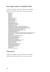
Install the video driver update from www.dell.com/support. Intel Chipset Software Installation Utility In the Device Manager, check if the chipset driver is installed. Video drivers In the Device Manager, check if the video driver is installed. Install the Intel chipset updates from www.dell.com/support. 108
Install the video driver update from www.dell.com/support. Intel Chipset Software Installation Utility In the Device Manager, check if the chipset driver is installed. Video drivers In the Device Manager, check if the video driver is installed. Install the Intel chipset updates from www.dell.com/support. 108

Alienware Steam Machine R2 Service Manual
Page 8
... as keyboard, mouse, monitor, and so on, from your computer. 6 Remove any media card and optical disc from the bottom USB-port. 7 After the computer is unplugged, press and hold the power button for shut-down your personal safety. 8 NOTE: If you ordered. NOTE: Remove the USB dongle from your computer, if applicable. Console Mode: On the Home screen, click Power → Shut down . - Windows 10: Click Start → Power...
... as keyboard, mouse, monitor, and so on, from your computer. 6 Remove any media card and optical disc from the bottom USB-port. 7 After the computer is unplugged, press and hold the power button for shut-down your personal safety. 8 NOTE: If you ordered. NOTE: Remove the USB dongle from your computer, if applicable. Console Mode: On the Home screen, click Power → Shut down . - Windows 10: Click Start → Power...

Alienware Steam Machine R2 Service Manual
Page 11
After working inside your computer CAUTION: Leaving stray or loose screws inside your computer may severely damage your computer. 1 Replace all screws and ensure that no stray screws remain inside your computer. 2 Connect any external devices, peripherals, or cables you removed before working on your computer. 3 Replace any media cards, discs, or any other parts that you removed before working on your computer. 4 Connect your computer and all attached devices to their electrical outlets. 5 Turn on your computer. 11
After working inside your computer CAUTION: Leaving stray or loose screws inside your computer may severely damage your computer. 1 Replace all screws and ensure that no stray screws remain inside your computer. 2 Connect any external devices, peripherals, or cables you removed before working on your computer. 3 Replace any media cards, discs, or any other parts that you removed before working on your computer. 4 Connect your computer and all attached devices to their electrical outlets. 5 Turn on your computer. 11

Alienware Steam Machine R2 Service Manual
Page 81
... memory technology used. 81 Displays the processor type. Displays the memory speed. Allows you to enter the service tag of your computer. Displays the total computer memory. Displays the current time in hh:mm:ss format. Main BIOS Revision BIOS Build Date System Name System Time System Date Service Tag Service Tag Input Asset Tag Processor Information Processor Type Processor ID Processor Core Count Processor L1 Cache Processor L2 Cache Processor L3 Cache Memory Information Memory Installed Memory Available Memory Running Speed Memory...
... memory technology used. 81 Displays the processor type. Displays the memory speed. Allows you to enter the service tag of your computer. Displays the total computer memory. Displays the current time in hh:mm:ss format. Main BIOS Revision BIOS Build Date System Name System Time System Date Service Tag Service Tag Input Asset Tag Processor Information Processor Type Processor ID Processor Core Count Processor L1 Cache Processor L2 Cache Processor L3 Cache Memory Information Memory Installed Memory Available Memory Running Speed Memory...

Alienware Steam Machine R2 Service Manual
Page 86
... optical drive to run Dell Diagnostics from and press Enter. For example, if you are booting to boot from : 86 change the sequence of devices that your computer. 3 When F2 Setup, F12 Boot Options appear in the lower-right corner of the screen, press F12. The previous boot sequence is restored at the next boot. • Future Boot Sequence - Changing boot sequence for example, to boot from the Drivers and Utilities disc or to a USB port. 2 Turn...
... optical drive to run Dell Diagnostics from and press Enter. For example, if you are booting to boot from : 86 change the sequence of devices that your computer. 3 When F2 Setup, F12 Boot Options appear in the lower-right corner of the screen, press F12. The previous boot sequence is restored at the next boot. • Future Boot Sequence - Changing boot sequence for example, to boot from the Drivers and Utilities disc or to a USB port. 2 Turn...

Alienware Steam Machine R2 Service Manual
Page 90
A message is displayed to confirm that the CMOS settings are reset and default BIOS setup has been loaded. 8 Press F1 to continue and wait till the operating system is completely loaded. 90 2 Remove the jumper plug from the password jumper (pin number three and four) and place it on the CMOS jumper (pin number five and six). 1 jumper plug 2 CMOS jumper (pin number five and six) 3 password jumper (pin number three and four) 3 Replace the video-card fan. 4 Replace the processor fan. 5 Replace the top cover. 6 Replace the base cover. 7 Turn on your computer.
A message is displayed to confirm that the CMOS settings are reset and default BIOS setup has been loaded. 8 Press F1 to continue and wait till the operating system is completely loaded. 90 2 Remove the jumper plug from the password jumper (pin number three and four) and place it on the CMOS jumper (pin number five and six). 1 jumper plug 2 CMOS jumper (pin number five and six) 3 password jumper (pin number three and four) 3 Replace the video-card fan. 4 Replace the processor fan. 5 Replace the top cover. 6 Replace the base cover. 7 Turn on your computer.

Alienware Graphics Amplifier Users Guide
Page 5
... attached peripherals, such as keyboard, mouse, monitor, and so on the configuration you finish working inside the device, replace all power sources before connecting to protect your device from potential damage and ensure your personal safety. Safety Instructions Use the following safety guidelines to the power source. WARNING: Disconnect all covers, panels, and screws before opening the device cover or panels. CAUTION: To avoid damaging the device, make sure that ships with...
... attached peripherals, such as keyboard, mouse, monitor, and so on the configuration you finish working inside the device, replace all power sources before connecting to protect your device from potential damage and ensure your personal safety. Safety Instructions Use the following safety guidelines to the power source. WARNING: Disconnect all covers, panels, and screws before opening the device cover or panels. CAUTION: To avoid damaging the device, make sure that ships with...


