
Service Manual
Page 10
After working inside your computer CAUTION: Leaving stray or loose screws inside your computer may severely damage your computer. 1 Replace all screws and ensure that no stray screws remain inside your computer. 2 Connect any external devices, peripherals, or cables you removed before working on your computer. 3 Replace any media cards, discs, or any other parts that you removed before working on your computer. 4 Connect your computer and all attached devices to their electrical outlets. 5 Turn on your computer. 10
After working inside your computer CAUTION: Leaving stray or loose screws inside your computer may severely damage your computer. 1 Replace all screws and ensure that no stray screws remain inside your computer. 2 Connect any external devices, peripherals, or cables you removed before working on your computer. 3 Replace any media cards, discs, or any other parts that you removed before working on your computer. 4 Connect your computer and all attached devices to their electrical outlets. 5 Turn on your computer. 10

Service Manual
Page 11
.../regulatory_compliance. WARNING: Disconnect all covers, panels, and screws before connecting to the electrical outlet. CAUTION: You should only perform troubleshooting and repairs as the metal at the back of the computer. Some cables have connectors with locking tabs or thumb-screws that is not authorized by the Dell technical assistance team. CAUTION: When you finish working inside your computer, ground yourself...
.../regulatory_compliance. WARNING: Disconnect all covers, panels, and screws before connecting to the electrical outlet. CAUTION: You should only perform troubleshooting and repairs as the metal at the back of the computer. Some cables have connectors with locking tabs or thumb-screws that is not authorized by the Dell technical assistance team. CAUTION: When you finish working inside your computer, ground yourself...

Service Manual
Page 35
After working inside your computer, follow the steps in After working inside your computer. Prerequisites Remove the left-side cover. Procedure 1 Disconnect the data and power cables from the hard drive. 2 Press the release tabs on the hard-drive carrier and slide the hard-drive carrier out of the hard-drive cage. 3 Pry the hard-drive carrier to release the tabs on the carrier from the slots on the hard drive. 35...
After working inside your computer, follow the steps in After working inside your computer. Prerequisites Remove the left-side cover. Procedure 1 Disconnect the data and power cables from the hard drive. 2 Press the release tabs on the hard-drive carrier and slide the hard-drive carrier out of the hard-drive cage. 3 Pry the hard-drive carrier to release the tabs on the carrier from the slots on the hard drive. 35...

Service Manual
Page 39
... computer and follow the instructions in Before working inside your computer. Procedure 1 Disconnect the data and power cables from the hard drive. 2 Press the release tabs on the hard-drive carrier and slide the hard-drive carrier out of the hard-drive cage. 3 Pry the hard-drive carrier to release the tabs on the carrier from the slots on the hard drive. 39 After working inside your computer, follow the...
... computer and follow the instructions in Before working inside your computer. Procedure 1 Disconnect the data and power cables from the hard drive. 2 Press the release tabs on the hard-drive carrier and slide the hard-drive carrier out of the hard-drive cage. 3 Pry the hard-drive carrier to release the tabs on the carrier from the slots on the hard drive. 39 After working inside your computer, follow the...
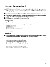
Service Manual
Page 99
You must make the appropriate changes again after you replace the system board. Procedure NOTE: Note the routing of the connectors so that you can reroute them so that shipped with your computer and follow the instructions in the BIOS setup program after you have made to step 4 in "Removing the power-supply unit". 3 Remove the memory modules. 4 Remove the solid-state drive. 5 Remove the wireless card. 6 Remove the processor fan and...
You must make the appropriate changes again after you replace the system board. Procedure NOTE: Note the routing of the connectors so that you can reroute them so that shipped with your computer and follow the instructions in the BIOS setup program after you have made to step 4 in "Removing the power-supply unit". 3 Remove the memory modules. 4 Remove the solid-state drive. 5 Remove the wireless card. 6 Remove the processor fan and...
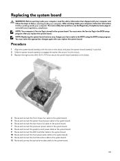
Service Manual
Page 101
... connect the top-chassis fan cable to the system board. 7 Route and connect the processor power cable to the system board. 8 Route and connect the graphics-card power cable to the system board. 9 Route and connect the LED controller cable to the system board. 10 Route and connect the front panel audio cable to the system board. 11 Route and connect the hard drive data cable to the system board. 12 Route and connect the optical drive data cable to the system board. 101 After working inside...
... connect the top-chassis fan cable to the system board. 7 Route and connect the processor power cable to the system board. 8 Route and connect the graphics-card power cable to the system board. 9 Route and connect the LED controller cable to the system board. 10 Route and connect the front panel audio cable to the system board. 11 Route and connect the hard drive data cable to the system board. 12 Route and connect the optical drive data cable to the system board. 101 After working inside...

Service Manual
Page 103
...; Removable Drive (if available) • STXXXX Drive NOTE: XXX denotes the SATA drive number. • Optical Drive (if available) • SATA Hard Drive (if available) • Diagnostics NOTE: Choosing Diagnostics, will display the ePSA diagnostics screen. System setup NOTE: Depending on Self Test (POST), when the Dell logo appears, you can: • Access System Setup by pressing F2 key • Bring up the one-time boot menu by pressing F12 key The one-time boot menu displays the devices...
...; Removable Drive (if available) • STXXXX Drive NOTE: XXX denotes the SATA drive number. • Optical Drive (if available) • SATA Hard Drive (if available) • Diagnostics NOTE: Choosing Diagnostics, will display the ePSA diagnostics screen. System setup NOTE: Depending on Self Test (POST), when the Dell logo appears, you can: • Access System Setup by pressing F2 key • Bring up the one-time boot menu by pressing F12 key The one-time boot menu displays the devices...
Service Manual
Page 104
... as the amount of RAM and the size of the hard drive. • Change the system configuration information. • Set or change a user-selectable option, such as the user password, type of the processor. Displays the processor type Displays the speed of hard drive installed, and enabling or disabling base devices. If you see the desktop. Entering BIOS setup program 1 Turn on your computer and its installed devices, the items listed in your computer. Displays the product name. Use the BIOS Setup program for it, and...
... as the amount of RAM and the size of the hard drive. • Change the system configuration information. • Set or change a user-selectable option, such as the user password, type of the processor. Displays the processor type Displays the speed of hard drive installed, and enabling or disabling base devices. If you see the desktop. Entering BIOS setup program 1 Turn on your computer and its installed devices, the items listed in your computer. Displays the product name. Use the BIOS Setup program for it, and...

Service Manual
Page 105
... external devices. This option can be configured only if the Auto Power On mode is set to wake the system from Hard Drive USB Configuration Front USB Ports Rear USB Ports Power Options Numlock Key Wake Up by special LAN signals. Allows you to enable front the USB devices to Enabled hh:mm:ss. 105 Allows you to 31. Table 4. Allows you to set the status of the integrated SATA hard drive controller. Allows you to define the controls when Deep Sleep is restored...
... external devices. This option can be configured only if the Auto Power On mode is set to wake the system from Hard Drive USB Configuration Front USB Ports Rear USB Ports Power Options Numlock Key Wake Up by special LAN signals. Allows you to enable front the USB devices to Enabled hh:mm:ss. 105 Allows you to 31. Table 4. Allows you to set the status of the integrated SATA hard drive controller. Allows you to define the controls when Deep Sleep is restored...

Service Manual
Page 106
System setup options-Boot menu Boot Boot List Option File Browser Add Boot Option File Browser Del Boot Option Secure Boot Control Load Legacy OPROM Boot Option Priorities Boot Option #1 Boot Option #2 Boot Option #3 Allows you to set the core ratio limit. Allows you enable or disable the OC level1/level2 setting and adjust the processor flex ratio and voltage in the Customization mode. Displays the system password. Displays the first boot device. Displays the hard drive password. Allows you to select between adaptive and override voltage modes. Default: Onboard ...
System setup options-Boot menu Boot Boot List Option File Browser Add Boot Option File Browser Del Boot Option Secure Boot Control Load Legacy OPROM Boot Option Priorities Boot Option #1 Boot Option #2 Boot Option #3 Allows you to set the core ratio limit. Allows you enable or disable the OC level1/level2 setting and adjust the processor flex ratio and voltage in the Customization mode. Displays the system password. Displays the first boot device. Displays the hard drive password. Allows you to select between adaptive and override voltage modes. Default: Onboard ...

Service Manual
Page 110
... POST, the computer emits a series of LED codes in a normal mode. Note the error code and contact Dell. Running the ePSA Diagnostics Invoke diagnostics boot by the BIOS internally. The ePSA is displayed. 3 In the boot menu screen, use Up/Down arrow key to select the Diagnostics option and then press Enter. The detected items are listed and tested. 5 To run a diagnostic test on a specific device, press Esc and click Yes to test only your hardware. If the computer passes the...
... POST, the computer emits a series of LED codes in a normal mode. Note the error code and contact Dell. Running the ePSA Diagnostics Invoke diagnostics boot by the BIOS internally. The ePSA is displayed. 3 In the boot menu screen, use Up/Down arrow key to select the Diagnostics option and then press Enter. The detected items are listed and tested. 5 To run a diagnostic test on a specific device, press Esc and click Yes to test only your hardware. If the computer passes the...
Service Manual
Page 111
... see Dell Windows Backup Media and Recovery Options. 111 Diagnostics Number of Power LED flashes 1 2 3 4 5 6 7 3,6 3,7 Problem description System board: BIOS and ROM failure No memory or RAM detected System board or chipset error Memory or RAM failure CMOS battery failure Video card or chip failure CPU failure BIOS recovery image not found BIOS recovery image found but invalid Flashing BIOS (USB key) 1 Follow the procedure from the One Time Boot Menu. 7 Type the BIOS setup program filename and press Enter. 8 The BIOS Update Utility appears. Follow these steps to flash the BIOS: 1 Turn...
... see Dell Windows Backup Media and Recovery Options. 111 Diagnostics Number of Power LED flashes 1 2 3 4 5 6 7 3,6 3,7 Problem description System board: BIOS and ROM failure No memory or RAM detected System board or chipset error Memory or RAM failure CMOS battery failure Video card or chip failure CPU failure BIOS recovery image not found BIOS recovery image found but invalid Flashing BIOS (USB key) 1 Follow the procedure from the One Time Boot Menu. 7 Type the BIOS setup program filename and press Enter. 8 The BIOS Update Utility appears. Follow these steps to flash the BIOS: 1 Turn...
Setup and Specifications
Page 3
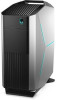
... your computer...4 Create a USB recovery drive for Windows 6 Setting up the Virtual Reality (VR) headset - optional 7 Views of Alienware Aurora R8 8 Front...8 Back...9 Back panel...10 Specifications of Alienware Aurora R8 12 Dimensions and weight...12 Processors...12 Chipset...12 Operating system...13 Memory...13 Intel Optane memory...13 Ports and connectors...14 Communications...15 Ethernet...15 Wireless module...15 Video...15 Audio...16 Storage...16 Power ratings...17 Computer environment...17 Getting help and...
... your computer...4 Create a USB recovery drive for Windows 6 Setting up the Virtual Reality (VR) headset - optional 7 Views of Alienware Aurora R8 8 Front...8 Back...9 Back panel...10 Specifications of Alienware Aurora R8 12 Dimensions and weight...12 Processors...12 Chipset...12 Operating system...13 Memory...13 Intel Optane memory...13 Ports and connectors...14 Communications...15 Ethernet...15 Wireless module...15 Video...15 Audio...16 Storage...16 Power ratings...17 Computer environment...17 Getting help and...
Setup and Specifications
Page 8
Provides data transfer speeds up to 5 Gbps. 2 Headphone port Connect a headphone or speakers. 3 Microphone port Connect an external microphone to provide sound input. 4 USB 3.1 Gen 1 Type-C port Connect to external storage devices. Press and hold for 4 seconds to 5 Gbps. Provides data transfer speeds up to 5 Gbps. 6 Optical-drive eject button Press to open the optical drive tray. 7 Optical drive (optional) Reads from and writes to CDs, DVDs, and Blu‑ray discs. 8 Power button (AlienHead) Press to put the...
Provides data transfer speeds up to 5 Gbps. 2 Headphone port Connect a headphone or speakers. 3 Microphone port Connect an external microphone to provide sound input. 4 USB 3.1 Gen 1 Type-C port Connect to external storage devices. Press and hold for 4 seconds to 5 Gbps. Provides data transfer speeds up to 5 Gbps. 6 Optical-drive eject button Press to open the optical drive tray. 7 Optical drive (optional) Reads from and writes to CDs, DVDs, and Blu‑ray discs. 8 Power button (AlienHead) Press to put the...

Setup and Specifications
Page 9
... installed in Power Options. NOTE: The PCI-Express X16 slot works at X8 speed only. For optimal graphics performance, use a PCI-Express X16 slot for connecting the graphics card. Back 1 Back panel Connect USB, audio, video, and other devices. 2 PCI-Express X16 (graphics slot 1) Connect a PCI-Express card such as graphics, audio, or network card to enhance the capabilities of your computer. For optimal graphics performance, use a PCI-Express X16 slot for connecting the graphics card. NOTE: If you to remove the power supply unit from your computer. 6 Power-supply diagnostics...
... installed in Power Options. NOTE: The PCI-Express X16 slot works at X8 speed only. For optimal graphics performance, use a PCI-Express X16 slot for connecting the graphics card. Back 1 Back panel Connect USB, audio, video, and other devices. 2 PCI-Express X16 (graphics slot 1) Connect a PCI-Express card such as graphics, audio, or network card to enhance the capabilities of your computer. For optimal graphics performance, use a PCI-Express X16 slot for connecting the graphics card. NOTE: If you to remove the power supply unit from your computer. 6 Power-supply diagnostics...
Setup and Specifications
Page 10
... Security-cable slot (for Kensington locks) Connect a security cable to the hard drive. 2 Optical S/PDIF port Connect an amplifier, speakers, or a TV for digital audio output through an optical cable. 3 USB 2.0 ports (5) Connect peripherals such as external storage devices and printers. Connect the display to 10 Gbps. 7 Side L/R surround port 10 Provides data transfer speeds up to 10 Gbps. 8 Power port Connect a power cable to provide power to your computer. 9 Service Tag label The Service Tag is covered. Back panel 1 Hard-drive activity light Turns on...
... Security-cable slot (for Kensington locks) Connect a security cable to the hard drive. 2 Optical S/PDIF port Connect an amplifier, speakers, or a TV for digital audio output through an optical cable. 3 USB 2.0 ports (5) Connect peripherals such as external storage devices and printers. Connect the display to 10 Gbps. 7 Side L/R surround port 10 Provides data transfer speeds up to 10 Gbps. 8 Power port Connect a power cable to provide power to your computer. 9 Service Tag label The Service Tag is covered. Back panel 1 Hard-drive activity light Turns on...

Setup and Specifications
Page 11
... data transfer speeds up to the connector indicate the connectivity status and network activity. 15 Coaxial S/PDIF port Connect an amplifier, speakers, or a TV for network or Internet access. The two lights next to 5 Gbps. 14 Network port (with the speakers. 12 Rear L/R surround port Connect audio-output devices such as speakers and amplifiers. NOTE: For more information about the speaker setup, refer the documentation that shipped with lights) Connect an Ethernet (RJ45) cable from a router...
... data transfer speeds up to the connector indicate the connectivity status and network activity. 15 Coaxial S/PDIF port Connect an amplifier, speakers, or a TV for network or Internet access. The two lights next to 5 Gbps. 14 Network port (with the speakers. 12 Rear L/R surround port Connect audio-output devices such as speakers and amplifiers. NOTE: For more information about the speaker setup, refer the documentation that shipped with lights) Connect an Ethernet (RJ45) cable from a router...

Setup and Specifications
Page 13
... (64-bit) Memory Table 4. Intel Optane memory specifications Description Type Interface Connector Values Storage accelarator PCIe 3.0x4 M.2 2280 13 Memory specifications Description Slots Type Speed Maximum memory Minimum memory Memory per slot Configurations supported Values Four DIMM sockets DDR4 • 2666 MHz • Up to the memory (RAM) installed on computers that meet the following requirements: • 7th Generation or higher Intel Core i3/i5/i7 processor • Windows 10 64...
... (64-bit) Memory Table 4. Intel Optane memory specifications Description Type Interface Connector Values Storage accelarator PCIe 3.0x4 M.2 2280 13 Memory specifications Description Slots Type Speed Maximum memory Minimum memory Memory per slot Configurations supported Values Four DIMM sockets DDR4 • 2666 MHz • Up to the memory (RAM) installed on computers that meet the following requirements: • 7th Generation or higher Intel Core i3/i5/i7 processor • Windows 10 64...

Setup and Specifications
Page 14
...-in port One DisplayPort - Internal ports and connectors specifications Description Expansion 14 Values 16 GB and 32 GB Up to the discrete graphics card of your computer. Not supported Not supported Kensington locks Not supported Values • Two PCIe x16 slots Description Configurations supported Capacity Ports and connectors Table 6. optional NOTE: The DisplayPort on the back panel of your computer is covered. External ports and connectors specifications Description Front USB Audio Back Network USB Audio Video Media-card reader Power adapter port Security Legacy ports...
...-in port One DisplayPort - Internal ports and connectors specifications Description Expansion 14 Values 16 GB and 32 GB Up to the discrete graphics card of your computer. Not supported Not supported Kensington locks Not supported Values • Two PCIe x16 slots Description Configurations supported Capacity Ports and connectors Table 6. optional NOTE: The DisplayPort on the back panel of your computer is covered. External ports and connectors specifications Description Front USB Audio Back Network USB Audio Video Media-card reader Power adapter port Security Legacy ports...

Setup and Specifications
Page 16
Intel UHD Graphics 630 One DisplayPort NOTE: Use discrete card output for DVD+/-RW drive or Blue- Storage specifications Storage type Two 2.5-inch hard drives One 3.5-inch hard drive Two M.2 2242/2260/2280 solid-state drives Interface type SATA AHCI 6 Gbps SATA AHCI 6 Gbps • SATA AHCI 6 Gbps • PCIe NVMe up to 32 Gbps Capacity Up to 2 TB Up to 1 TB Up to 1 TB One U.2 drive PCIe...
Intel UHD Graphics 630 One DisplayPort NOTE: Use discrete card output for DVD+/-RW drive or Blue- Storage specifications Storage type Two 2.5-inch hard drives One 3.5-inch hard drive Two M.2 2242/2260/2280 solid-state drives Interface type SATA AHCI 6 Gbps SATA AHCI 6 Gbps • SATA AHCI 6 Gbps • PCIe NVMe up to 32 Gbps Capacity Up to 2 TB Up to 1 TB Up to 1 TB One U.2 drive PCIe...


