Service Manual
Page 3
... Alienware x14...9 Disassembly and reassembly ...11 Base cover...11 Battery...16 Wireless card...19 Solid-state drive...21 Rear-I/O cover...26 Touchpad...27 Keyboard-controller board...30 Speakers...32 Display assembly...35 System board...41 Fan and heat-sink assembly...48 Headset port...52 I/O board...55 Power button...57 Palm-rest and keyboard assembly...58 Chapter 3: Drivers and downloads...61 Chapter 4: System setup...62 Entering BIOS setup program...62 Navigation keys...62 Boot Sequence...62 System setup options...63 System and setup password...
... Alienware x14...9 Disassembly and reassembly ...11 Base cover...11 Battery...16 Wireless card...19 Solid-state drive...21 Rear-I/O cover...26 Touchpad...27 Keyboard-controller board...30 Speakers...32 Display assembly...35 System board...41 Fan and heat-sink assembly...48 Headset port...52 I/O board...55 Power button...57 Palm-rest and keyboard assembly...58 Chapter 3: Drivers and downloads...61 Chapter 4: System setup...62 Entering BIOS setup program...62 Navigation keys...62 Boot Sequence...62 System setup options...63 System and setup password...

Service Manual
Page 5
... perform troubleshooting and repairs as authorized or directed by touching an unpainted metal surface, such as keyboard, mouse, and monitor from your personal safety. CAUTION: Press and eject any media card and optical disc from your computer and all attached network devices and peripherals, such as the metal at the back of your operating system for shut-down instructions. 3. Steps 1. WARNING: Before working inside...
... perform troubleshooting and repairs as authorized or directed by touching an unpainted metal surface, such as keyboard, mouse, and monitor from your personal safety. CAUTION: Press and eject any media card and optical disc from your computer and all attached network devices and peripherals, such as the metal at the back of your operating system for shut-down instructions. 3. Steps 1. WARNING: Before working inside...

Service Manual
Page 6
... the internal wires of the time when damage occurs, it during service procedures. Use only Field Service kits with increased sensitivity to static damage is no longer applicable. Always be connected to the mat and to avoid accidental ESD hardware damage. Swollen batteries should not be used in an anti-static container or packaging. Very slight charges can be removed...
... the internal wires of the time when damage occurs, it during service procedures. Use only Field Service kits with increased sensitivity to static damage is no longer applicable. Always be connected to the mat and to avoid accidental ESD hardware damage. Swollen batteries should not be used in an anti-static container or packaging. Very slight charges can be removed...

Service Manual
Page 7
... are insulators and often highly charged. ● Working Environment - The workspace should always be moved at an ESD-protected work area, insulators such as replacement parts or parts to be free of insulators that the new part arrived in static-safe packaging. ESD-sensitive devices should be removed from internal parts that is critical to keep sensitive parts separate from sensitive parts before physically handling any...
... are insulators and often highly charged. ● Working Environment - The workspace should always be moved at an ESD-protected work area, insulators such as replacement parts or parts to be free of insulators that the new part arrived in static-safe packaging. ESD-sensitive devices should be removed from internal parts that is critical to keep sensitive parts separate from sensitive parts before physically handling any...

Service Manual
Page 17
.... Removing the battery Prerequisites 1. After a service incident where the computer battery is disconnected, when the battery is fully discharged, or when the computer is reassembled and turned on and off three times. For guidelines on how to default. Remove the base cover. The computer starts functioning normally after setting the date and time. It is recommended that you to enter the BIOS and configure the...
.... Removing the battery Prerequisites 1. After a service incident where the computer battery is disconnected, when the battery is fully discharged, or when the computer is reassembled and turned on and off three times. For guidelines on how to default. Remove the base cover. The computer starts functioning normally after setting the date and time. It is recommended that you to enter the BIOS and configure the...

Service Manual
Page 42
Speaker cable 9. Keyboard-controller board cable 11. Left-fan cable 6. Solid-state drive slot The following image(s) indicate the location of the system board and provides a visual representation of the removal procedure. 42 Wireless-card slot 8. 1. I/O-board cable 3. Headset port cable 5. Display cable 4. Right-fan cable 2. Battery cable 10. Power-button cable 7.
Speaker cable 9. Keyboard-controller board cable 11. Left-fan cable 6. Solid-state drive slot The following image(s) indicate the location of the system board and provides a visual representation of the removal procedure. 42 Wireless-card slot 8. 1. I/O-board cable 3. Headset port cable 5. Display cable 4. Right-fan cable 2. Battery cable 10. Power-button cable 7.

Service Manual
Page 44
... I /O-board cable. In order to access the connector. 4. Open the latch and disconnect the I /O-board cable, the Mylar must be lifted to disconnect the I /O-board cable from the gap between the system board and the left fan. 44 Open the latch and disconnect the headset-port cable from the system board. 7. Remove the nine screws (M2x4) that secure the display-cable bracket to the palm-rest and keyboard assembly...
... I /O-board cable. In order to access the connector. 4. Open the latch and disconnect the I /O-board cable, the Mylar must be lifted to disconnect the I /O-board cable from the gap between the system board and the left fan. 44 Open the latch and disconnect the headset-port cable from the system board. 7. Remove the nine screws (M2x4) that secure the display-cable bracket to the palm-rest and keyboard assembly...

Service Manual
Page 45
... to the system board. 15. I/O-board cable 3. Keyboard-controller board cable 2. Turn the system-board assembly over . 18. Remove the fan and heat-sink assembly. 17. Adhere the processor (CPU) sticker over the processor (CPU) chip and ensure that have Element 31 grease is only applicable for computers with the service kit. Wireless-card slot 8. Turn the system board over and place it on . Power-button cable 7. Lift the two USB Type-C port brackets off...
... to the system board. 15. I/O-board cable 3. Keyboard-controller board cable 2. Turn the system-board assembly over . 18. Remove the fan and heat-sink assembly. 17. Adhere the processor (CPU) sticker over the processor (CPU) chip and ensure that have Element 31 grease is only applicable for computers with the service kit. Wireless-card slot 8. Turn the system board over and place it on . Power-button cable 7. Lift the two USB Type-C port brackets off...

Service Manual
Page 62
Entering BIOS setup program About this task Turn on Self Test (POST), when the Dell logo appears, you can: ● Access System Setup by pressing F2 key ● Bring up the one-time boot menu by pressing F12 key The one-time boot menu displays the devices that you can make are recorded but do not change a user-selectable option, such as the user password, type of the System Setup options, changes that prompts you restart...
Entering BIOS setup program About this task Turn on Self Test (POST), when the Dell logo appears, you can: ● Access System Setup by pressing F2 key ● Bring up the one-time boot menu by pressing F12 key The one-time boot menu displays the devices that you can make are recorded but do not change a user-selectable option, such as the user password, type of the System Setup options, changes that prompts you restart...

Service Manual
Page 63
... type of memory installed. Displays the size of AC adapter. Displays the speed of a USB-aware operating system, handles USB devices. Table 4. This feature defines how the BIOS, in this option is always enabled during POST. Default: Enabled Allows you to configure the operating mode of the computer. Display the M.2 PCIe SSD device information of the integrated SATA hard drive controller. 63 System setup options-Advance menu Advance Integrated NIC USB Emulation USB PowerShare Enables or disables the Integrated NIC. Default: Enabled Enables...
... type of memory installed. Displays the size of AC adapter. Displays the speed of a USB-aware operating system, handles USB devices. Table 4. This feature defines how the BIOS, in this option is always enabled during POST. Default: Enabled Allows you to configure the operating mode of the computer. Display the M.2 PCIe SSD device information of the integrated SATA hard drive controller. 63 System setup options-Advance menu Advance Integrated NIC USB Emulation USB PowerShare Enables or disables the Integrated NIC. Default: Enabled Enables...

Service Manual
Page 64
...Default: Disabled Maintenance Data Wipe on next boot Enables or disables data wipe on the user primary hard drive or an external USB key. Default: Disabled 64 Default: 2 SupportAssist OS Recovery Enables or disables the boot flow for the Dell operating system Recovery tool. Default: Multimedia key Keyboard Backlight with Battery Selects the timeout value for the keyboard backlight when an AC adapter is open Selects the power-on battery power. Default: 1 minute Battery Health Battery Charge Configuration Displays the battery health. System setup options-Advance menu...
...Default: Disabled Maintenance Data Wipe on next boot Enables or disables data wipe on the user primary hard drive or an external USB key. Default: Disabled 64 Default: 2 SupportAssist OS Recovery Enables or disables the boot flow for the Dell operating system Recovery tool. Default: Multimedia key Keyboard Backlight with Battery Selects the timeout value for the keyboard backlight when an AC adapter is open Selects the power-on battery power. Default: 1 minute Battery Health Battery Charge Configuration Displays the battery health. System setup options-Advance menu...

Service Manual
Page 65
... in Windows Enables or disables UEFI boot. Default: Disabled Enables or disables the Windows SMM Security Mitigations Table. Default: Enabled Allows you to permit or deny system password or HDD password changes. It allows the system firmware to confirm to control the TPM Physical Presence Interface (PPI). System setup options-Boot menu Boot Boot List Option File Browser Add Boot Option Windows Boot Manager UEFI Boot Displays if the administrator password is clear or set . Default: Permitted Enables or disables the BIOS module interface of platform features on Dell Client...
... in Windows Enables or disables UEFI boot. Default: Disabled Enables or disables the Windows SMM Security Mitigations Table. Default: Enabled Allows you to permit or deny system password or HDD password changes. It allows the system firmware to confirm to control the TPM Physical Presence Interface (PPI). System setup options-Boot menu Boot Boot List Option File Browser Add Boot Option Windows Boot Manager UEFI Boot Displays if the administrator password is clear or set . Default: Permitted Enables or disables the BIOS module interface of platform features on Dell Client...

Service Manual
Page 66
... create a system password and a setup password to your changes. The computer restarts. 66 The Security screen is disabled. Allows you must enter to access and make changes to load previous values for the data on your computer. Password that you must enter to log on or reboot. In the System BIOS or System Setup screen, select Security and press Enter. Type the system password that you entered earlier in the Enter the new password...
... create a system password and a setup password to your changes. The computer restarts. 66 The Security screen is disabled. Allows you must enter to access and make changes to load previous values for the data on your computer. Password that you must enter to log on or reboot. In the System BIOS or System Setup screen, select Security and press Enter. Type the system password that you entered earlier in the Enter the new password...
Service Manual
Page 67
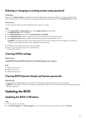
... system setup password Prerequisites Ensure that Password Status is Unlocked. 3. Select Setup Password, update, or delete the existing setup password, and press Enter or Tab. Remove the base cover. 2. Wait for one minute. 3. The System Security screen is Unlocked (in Windows Steps 1. In the System Security screen, verify that the Password Status is displayed. 2. Replace the base cover. Click Product support. Steps 1. Clearing CMOS settings About this task To clear the system or BIOS passwords, contact Dell technical support...
... system setup password Prerequisites Ensure that Password Status is Unlocked. 3. Select Setup Password, update, or delete the existing setup password, and press Enter or Tab. Remove the base cover. 2. Wait for one minute. 3. The System Security screen is Unlocked (in Windows Steps 1. In the System Security screen, verify that the Password Status is displayed. 2. Replace the base cover. Click Product support. Steps 1. Clearing CMOS settings About this task To clear the system or BIOS passwords, contact Dell technical support...

Service Manual
Page 68
... needs the BIOS update. 5. Restart the computer and press F12 . 6. Create a bootable USB drive. Copy the BIOS setup program file to download the latest BIOS setup program file. 2. Type the BIOS setup program filename and press Enter. Expand Find drivers. 4. Select the operating system installed on your computer model. 3. Follow the procedure from the One Time Boot Menu. 7. Follow the on -screen instructions. Select the USB drive from step 1 to step 6 in Updating the BIOS in Windows Steps 1. Updating...
... needs the BIOS update. 5. Restart the computer and press F12 . 6. Create a bootable USB drive. Copy the BIOS setup program file to download the latest BIOS setup program file. 2. Type the BIOS setup program filename and press Enter. Expand Find drivers. 4. Select the operating system installed on your computer model. 3. Follow the procedure from the One Time Boot Menu. 7. Follow the on -screen instructions. Select the USB drive from step 1 to step 6 in Updating the BIOS in Windows Steps 1. Updating...

Service Manual
Page 69
... or explosion. For more information on battery and the battery has less than 5% charge. These are as age, number of charge cycles, or exposure to find the Service Tag for your Dell Laptop. Locate the Service Tag or Express Service Code of your computer. Replace the battery only with a compatible battery purchased from Dell. Amber:Computer is connected and the battery has more information on how to improve...
... or explosion. For more information on battery and the battery has less than 5% charge. These are as age, number of charge cycles, or exposure to find the Service Tag for your Dell Laptop. Locate the Service Tag or Express Service Code of your computer. Replace the battery only with a compatible battery purchased from Dell. Amber:Computer is connected and the battery has more information on how to improve...

Service Manual
Page 70
... turned off , indicating no memory or RAM is detected. Ensure that indicate if problems were encountered during the test NOTE: Some tests are meant for specific devices and require user interaction. The following table shows different power and battery-status light patterns and associated problems. NOTE: The following diagnostic light codes and recommended solutions are performed. SBIOS message 3,1 Coin-cell battery failure 3,2 PCI, video card/chip failure 3,3 Recovery image...
... turned off , indicating no memory or RAM is detected. Ensure that indicate if problems were encountered during the test NOTE: Some tests are meant for specific devices and require user interaction. The following table shows different power and battery-status light patterns and associated problems. NOTE: The following diagnostic light codes and recommended solutions are performed. SBIOS message 3,1 Coin-cell battery failure 3,2 PCI, video card/chip failure 3,3 Recovery image...

Service Manual
Page 71
... a common troubleshooting step if your computer does not power on your computer. Recovering the operating system When your computer is unable to boot to conduct a WiFi power cycle: NOTE: Some ISPs (Internet Service Providers) provide a modem/router combo device. The following procedure provides the instructions on your computer. 71 Install the battery. 7. Turn on how to the operating system even after it automatically starts Dell SupportAssist OS Recovery.
... a common troubleshooting step if your computer does not power on your computer. Recovering the operating system When your computer is unable to boot to conduct a WiFi power cycle: NOTE: Some ISPs (Internet Service Providers) provide a modem/router combo device. The following procedure provides the instructions on your computer. 71 Install the battery. 7. Turn on how to the operating system even after it automatically starts Dell SupportAssist OS Recovery.

Setup and Specifications
Page 18
... Disable/enable Performance Boost Adjust keyboard backlight brightness Switch to external display Launch the Windows Connect app to perform multiple actions with a single key press. 18 List of the key is typed out. Keys that enable you press Shift + 2, @ is typed out. Some keys on your keyboard have two symbols on the lower part of the function keys (F1-F12) by pressing fn and the respective function key. However, if the function keys F1-F12 are needed...
... Disable/enable Performance Boost Adjust keyboard backlight brightness Switch to external display Launch the Windows Connect app to perform multiple actions with a single key press. 18 List of the key is typed out. Keys that enable you press Shift + 2, @ is typed out. Some keys on your keyboard have two symbols on the lower part of the function keys (F1-F12) by pressing fn and the respective function key. However, if the function keys F1-F12 are needed...

Setup and Specifications
Page 21
..., lighting, macros, and audio that are critical to your computer is available in Alienware Command Center. AWCC also supports Sound Management, Thermal Controls, CPU, GPU, Memory (RAM) monitoring. AlienFX enables you to create your own individual lighting effects and apply them to enhance the gaming experience. For more information about the location of AlienFX Lighting Zones on your computer or game. AWCC also supports AlienFX 2.0. You can quickly access settings...
..., lighting, macros, and audio that are critical to your computer is available in Alienware Command Center. AWCC also supports Sound Management, Thermal Controls, CPU, GPU, Memory (RAM) monitoring. AlienFX enables you to create your own individual lighting effects and apply them to enhance the gaming experience. For more information about the location of AlienFX Lighting Zones on your computer or game. AWCC also supports AlienFX 2.0. You can quickly access settings...


