Handling swollen Lithium-ion batteries
Page 1
... not bend the battery. ● Do not use of fire or explosion. Document Number: A05 Rev. We recommend contacting Dell product support for options to replace a swollen battery under the terms of the applicable warranty or service contract, including options for a slim form factor (especially with foreign objects. ● Do not expose the battery to high temperatures, or disassemble battery packs and cells...
... not bend the battery. ● Do not use of fire or explosion. Document Number: A05 Rev. We recommend contacting Dell product support for options to replace a swollen battery under the terms of the applicable warranty or service contract, including options for a slim form factor (especially with foreign objects. ● Do not expose the battery to high temperatures, or disassemble battery packs and cells...

Inspiron 15 7000 Service Manual
Page 1
Inspiron 15 7000 Service Manual Computer Model: Inspiron 15-7560 Regulatory Model: P61F Regulatory Type: P61F001
Inspiron 15 7000 Service Manual Computer Model: Inspiron 15-7560 Regulatory Model: P61F Regulatory Type: P61F001

Inspiron 15 7000 Service Manual
Page 5
Replacing the wireless card 35 Procedure 35 Post-requisites 36 Removing the display assembly 37 Prerequisites 37 Procedure 37 Replacing the display assembly 41 Procedure 41 Post-requisites 41 Removing the I/O board 42 Prerequisites 42 Procedure 42 Replacing the I/O board 44 Procedure 44 Post-requisites 44 Removing the memory modules 45 Prerequisites 45 Procedure 45 Replacing the memory modules 47 Procedure 47 Post-requisites 48 Removing the speakers 49 Prerequisites 49 Procedure 49 5
Replacing the wireless card 35 Procedure 35 Post-requisites 36 Removing the display assembly 37 Prerequisites 37 Procedure 37 Replacing the display assembly 41 Procedure 41 Post-requisites 41 Removing the I/O board 42 Prerequisites 42 Procedure 42 Replacing the I/O board 44 Procedure 44 Post-requisites 44 Removing the memory modules 45 Prerequisites 45 Procedure 45 Replacing the memory modules 47 Procedure 47 Post-requisites 48 Removing the speakers 49 Prerequisites 49 Procedure 49 5

Inspiron 15 7000 Service Manual
Page 8
... operating system for shut-down instructions. 3 Disconnect your computer and all attached devices from their electrical outlets. 4 Disconnect all cables such as telephone cables and network cables, from your computer. 5 Disconnect all attached devices and peripherals, such as keyboard, mouse, and monitor, from your computer. 6 Remove any media card and optical disc from potential damage and ensure your personal safety. WARNING: Disconnect all power sources before connecting...
... operating system for shut-down instructions. 3 Disconnect your computer and all attached devices from their electrical outlets. 4 Disconnect all cables such as telephone cables and network cables, from your computer. 5 Disconnect all attached devices and peripherals, such as keyboard, mouse, and monitor, from your computer. 6 Remove any media card and optical disc from potential damage and ensure your personal safety. WARNING: Disconnect all power sources before connecting...

Inspiron 15 7000 Service Manual
Page 9
... by the Dell technical assistance team. When connecting cables, ensure that you disconnect a cable, pull on its connector or on its pull tab, not on the cable itself. CAUTION: To avoid damaging the computer, ensure that the work , periodically touch an unpainted metal surface to avoid bending any installed card from the media-card reader. CAUTION: You should only perform troubleshooting and repairs as...
... by the Dell technical assistance team. When connecting cables, ensure that you disconnect a cable, pull on its connector or on its pull tab, not on the cable itself. CAUTION: To avoid damaging the computer, ensure that the work , periodically touch an unpainted metal surface to avoid bending any installed card from the media-card reader. CAUTION: You should only perform troubleshooting and repairs as...

Inspiron 15 7000 Service Manual
Page 12
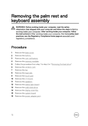
After working inside your computer CAUTION: Leaving stray or loose screws inside your computer may severely damage your computer. 1 Replace all screws and ensure that no stray screws remain inside your computer. 2 Connect any external devices, peripherals, or cables you removed before working on your computer. 3 Replace any media cards, discs, or any other parts that you removed before working on your computer. 4 Connect your computer and all attached devices to their electrical outlets. 5 Turn on your computer. 12
After working inside your computer CAUTION: Leaving stray or loose screws inside your computer may severely damage your computer. 1 Replace all screws and ensure that no stray screws remain inside your computer. 2 Connect any external devices, peripherals, or cables you removed before working on your computer. 3 Replace any media cards, discs, or any other parts that you removed before working on your computer. 4 Connect your computer and all attached devices to their electrical outlets. 5 Turn on your computer. 12

Inspiron 15 7000 Service Manual
Page 19
CAUTION: Removing the coin-cell battery resets the BIOS setup program's settings to default. It is recommended that shipped with your computer and follow the instructions in Before working inside your computer. Removing the coin-cell battery WARNING: Before working inside your computer, read the safety information that you note the BIOS setup program's settings before removing the coin-cell battery. For more safety best practices, see the...
CAUTION: Removing the coin-cell battery resets the BIOS setup program's settings to default. It is recommended that shipped with your computer and follow the instructions in Before working inside your computer. Removing the coin-cell battery WARNING: Before working inside your computer, read the safety information that you note the BIOS setup program's settings before removing the coin-cell battery. For more safety best practices, see the...

Inspiron 15 7000 Service Manual
Page 38
2 Open the latch and disconnect the display cable from the system board. 3 Open the display at an angle of 90 degrees. 4 Place the computer on the edge of a table so that the palm rest and keyboard assembly is on the table and the display assembly extends past the table edge with the display hinges facing up. 5 Remove the four screws (M2.5x5) that secure the display hinges to the palm rest and keyboard assembly. 38
2 Open the latch and disconnect the display cable from the system board. 3 Open the display at an angle of 90 degrees. 4 Place the computer on the edge of a table so that the palm rest and keyboard assembly is on the table and the display assembly extends past the table edge with the display hinges facing up. 5 Remove the four screws (M2.5x5) that secure the display hinges to the palm rest and keyboard assembly. 38

Inspiron 15 7000 Service Manual
Page 45
... base cover. 2 Remove the battery. Removing the memory modules WARNING: Before working inside your computer, read the safety information that shipped with your computer and follow the instructions in Before working inside your computer. After working inside your computer, follow the steps in After working inside your fingertips to carefully spread apart the securing clips on each end of the memory-module slot until the memory module...
... base cover. 2 Remove the battery. Removing the memory modules WARNING: Before working inside your computer, read the safety information that shipped with your computer and follow the instructions in Before working inside your computer. After working inside your computer, follow the steps in After working inside your fingertips to carefully spread apart the securing clips on each end of the memory-module slot until the memory module...

Inspiron 15 7000 Service Manual
Page 48
2 Slide the memory module firmly into place. Post-requisites 1 Replace the battery. 2 Replace the base cover. 48 NOTE: If you do not hear the click, remove the memory module and reinstall it clicks into the slot at an angle and press the memory module down until it .
2 Slide the memory module firmly into place. Post-requisites 1 Replace the battery. 2 Replace the base cover. 48 NOTE: If you do not hear the click, remove the memory module and reinstall it clicks into the slot at an angle and press the memory module down until it .

Inspiron 15 7000 Service Manual
Page 64
... follow the instructions in Before working inside your computer. After working inside your computer, follow the steps in After working inside your computer. Prerequisites 1 Remove the base cover. 2 Remove the battery. 3 Remove the memory modules. 4 Remove the wireless card. 5 Remove the fan. 6 Remove the heat sink. 7 Remove the solid-state drive. 8 Follow the procedure from step 1 to the BIOS using the BIOS setup program. NOTE: Replacing the system board removes any changes you replace the system board. NOTE: Your...
... follow the instructions in Before working inside your computer. After working inside your computer, follow the steps in After working inside your computer. Prerequisites 1 Remove the base cover. 2 Remove the battery. 3 Remove the memory modules. 4 Remove the wireless card. 5 Remove the fan. 6 Remove the heat sink. 7 Remove the solid-state drive. 8 Follow the procedure from step 1 to the BIOS using the BIOS setup program. NOTE: Replacing the system board removes any changes you replace the system board. NOTE: Your...

Inspiron 15 7000 Service Manual
Page 67
... latch to secure the cable. 8 Connect the power-adapter port cable to the BIOS using the BIOS setup program. NOTE: Replacing the system board removes any changes you replace the system board. You must make the appropriate changes again after you have made to the system board. 67 You must enter the Service Tag in Before working inside your computer. NOTE: Your computer's Service Tag is stored in After working inside your computer. For...
... latch to secure the cable. 8 Connect the power-adapter port cable to the BIOS using the BIOS setup program. NOTE: Replacing the system board removes any changes you replace the system board. You must make the appropriate changes again after you have made to the system board. 67 You must enter the Service Tag in Before working inside your computer. NOTE: Your computer's Service Tag is stored in After working inside your computer. For...

Inspiron 15 7000 Service Manual
Page 69
....dell.com/ regulatory_compliance. Prerequisites 1 Remove the base cover. 2 Remove the battery. 3 Remove the memory modules. 4 Remove the wireless card. 5 Remove the fan. 6 Remove the heat sink. 7 Remove the solid-state drive. 8 Follow the procedure from the routing guides on the palm rest and keyboard assembly. 2 Remove the screw (M2x3) that shipped with your computer and follow the instructions in "Removing the hard drive". 9 Remove the system board. 10 Remove the display assembly. Procedure 1 Note the power-adapter port cable routing and remove...
....dell.com/ regulatory_compliance. Prerequisites 1 Remove the base cover. 2 Remove the battery. 3 Remove the memory modules. 4 Remove the wireless card. 5 Remove the fan. 6 Remove the heat sink. 7 Remove the solid-state drive. 8 Follow the procedure from the routing guides on the palm rest and keyboard assembly. 2 Remove the screw (M2x3) that shipped with your computer and follow the instructions in "Removing the hard drive". 9 Remove the system board. 10 Remove the display assembly. Procedure 1 Note the power-adapter port cable routing and remove...
Inspiron 15 7000 Service Manual
Page 72
... the instructions in After working inside your computer. After working inside your computer, follow the steps in "Removing the hard drive". 6 Remove the wireless card. 7 Remove the fan. 8 Remove the heat sink. 9 Remove the touch pad. 10 Remove the I/O board. 11 Remove the speakers. 12 Remove the status-light board. 13 Remove the solid-state drive. 14 Remove the display assembly. 15 Remove the system board. 16 Remove the power-adapter port. 72 Procedure 1 Remove the base cover. 2 Remove the battery. 3 Remove the coin-cell battery. 4 Remove the memory modules. 5 Follow...
... the instructions in After working inside your computer. After working inside your computer, follow the steps in "Removing the hard drive". 6 Remove the wireless card. 7 Remove the fan. 8 Remove the heat sink. 9 Remove the touch pad. 10 Remove the I/O board. 11 Remove the speakers. 12 Remove the status-light board. 13 Remove the solid-state drive. 14 Remove the display assembly. 15 Remove the system board. 16 Remove the power-adapter port. 72 Procedure 1 Remove the base cover. 2 Remove the battery. 3 Remove the coin-cell battery. 4 Remove the memory modules. 5 Follow...

Inspiron 15 7000 Service Manual
Page 76
... connected and the battery has more than 5 percent charge. • Computer is in sleep state, hibernation, or turned off indicating no memory or RAM is running on battery and the battery has less than 5 percent charge. The power and battery-status light blinks amber along with beep codes indicating failures. Light Pattern 2,1 2,2 2,3 2,4 Problem description CPU failure System board: BIOS and ROM failure No memory or RAM detected Memory or RAM failure 76 NOTE: Press Fn+H to the hard drive. Hard-drive activity light Turns...
... connected and the battery has more than 5 percent charge. • Computer is in sleep state, hibernation, or turned off indicating no memory or RAM is running on battery and the battery has less than 5 percent charge. The power and battery-status light blinks amber along with beep codes indicating failures. Light Pattern 2,1 2,2 2,3 2,4 Problem description CPU failure System board: BIOS and ROM failure No memory or RAM detected Memory or RAM failure 76 NOTE: Press Fn+H to the hard drive. Hard-drive activity light Turns...

Inspiron 15 7000 Service Manual
Page 77
... memory installed System board or chipset error LCD failure CMOS battery failure PCI or video card or chip failure Recovery image not found Recovery image found but invalid The computer may emit a series of beeps during start-up if the errors or problems cannot be displayed. The repetitive beep codes help the user troubleshoot problems with the computer. Camera is enabled or disabled. • Solid white - Caps Lock status light: Indicates whether Caps Lock is not in use...
... memory installed System board or chipset error LCD failure CMOS battery failure PCI or video card or chip failure Recovery image not found Recovery image found but invalid The computer may emit a series of beeps during start-up if the errors or problems cannot be displayed. The repetitive beep codes help the user troubleshoot problems with the computer. Camera is enabled or disabled. • Solid white - Caps Lock status light: Indicates whether Caps Lock is not in use...

Inspiron 15 7000 Setup and Specifications
Page 3
Contents Set up your Inspiron 15-7560 5 Views of Inspiron 15-7560 7 Front...7 Left...7 Right...8 Base...9 Display...10 Bottom...11 Specifications of Inspiron 15-7560 12 Computer model 12 System information 12 Dimensions and weight 12 Memory 13 Ports and connectors 13 Communications 14 Audio...14 Storage 14 Media-card reader 15 Keyboard 15 Camera 16 Touchpad 16 3
Contents Set up your Inspiron 15-7560 5 Views of Inspiron 15-7560 7 Front...7 Left...7 Right...8 Base...9 Display...10 Bottom...11 Specifications of Inspiron 15-7560 12 Computer model 12 System information 12 Dimensions and weight 12 Memory 13 Ports and connectors 13 Communications 14 Audio...14 Storage 14 Media-card reader 15 Keyboard 15 Camera 16 Touchpad 16 3
Inspiron 15 7000 Setup and Specifications
Page 5
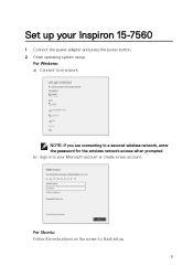
NOTE: If you are connecting to a network. For Windows: a) Connect to a secured wireless network, enter the password for the wireless network access when prompted. For Ubuntu: Follow the instructions on the screen to your Inspiron 15-7560 1 Connect the power adapter and press the power button. 2 Finish operating system setup. b) Sign in to finish setup. 5 Set up your Microsoft account or create a new account.
NOTE: If you are connecting to a network. For Windows: a) Connect to a secured wireless network, enter the password for the wireless network access when prompted. For Ubuntu: Follow the instructions on the screen to your Inspiron 15-7560 1 Connect the power adapter and press the power button. 2 Finish operating system setup. b) Sign in to finish setup. 5 Set up your Microsoft account or create a new account.

Inspiron 15 7000 Setup and Specifications
Page 7
... than 5% charge. Power adapter is running on when the computer reads from or writes to toggle between the power and battery-status light, and hard-drive activity light. Computer is connected and the battery has more than 5% charge. Left 7 Hard-drive activity light Turns on battery and the battery has more than 5% charge. - NOTE: Press Fn+H to the hard drive. Power and battery-status light Indicates the power and battery-charge status. Amber - Views of Inspiron 15-7560 Front 1 Power and battery-status light/hard-drive activity light Indicates the battery-charge status...
... than 5% charge. Power adapter is running on when the computer reads from or writes to toggle between the power and battery-status light, and hard-drive activity light. Computer is connected and the battery has more than 5% charge. Left 7 Hard-drive activity light Turns on battery and the battery has more than 5% charge. - NOTE: Press Fn+H to the hard drive. Power and battery-status light Indicates the power and battery-charge status. Amber - Views of Inspiron 15-7560 Front 1 Power and battery-status light/hard-drive activity light Indicates the battery-charge status...
Inspiron 15 7000 Setup and Specifications
Page 15
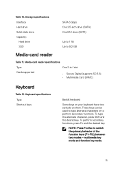
... key mode and function key mode. 15 Media-card reader specifications Type One 2-in-1 slot Cards supported • Secure Digital (supports SD 3.0) • Multimedia Card (MMC) Keyboard Table 12. These keys can be used to type alternate characters or to switch the primary behavior of the function keys (F1-F12) between two modes - NOTE: Press Fn+Esc to perform secondary functions. Keyboard specifications Type Shortcut keys Backlit keyboard Some keys on your keyboard have two symbols on them. Table 10. Storage specifications Interface Hard drive...
... key mode and function key mode. 15 Media-card reader specifications Type One 2-in-1 slot Cards supported • Secure Digital (supports SD 3.0) • Multimedia Card (MMC) Keyboard Table 12. These keys can be used to type alternate characters or to switch the primary behavior of the function keys (F1-F12) between two modes - NOTE: Press Fn+Esc to perform secondary functions. Keyboard specifications Type Shortcut keys Backlit keyboard Some keys on your keyboard have two symbols on them. Table 10. Storage specifications Interface Hard drive...


