
Owners Manual
Page 3
... 3: Specifications of Inspiron 3030 Small Desktop 14 Dimensions and weight...14 Processor...14 Chipset...15 Operating system...15 Memory...15 Memory matrix...16 External ports...16 Internal slots...17 Ethernet...17 Wireless module...17 Audio...18 Storage...18 Media-card reader...19 Power ratings...19 Power supply connector...20 GPU-Integrated...20 Multiple display support matrix...20 Hardware security...21 Environmental...21 Regulatory compliance...21 Operating and storage environment...21 Dell support policy...22 Chapter 4: Working inside your computer 23 Safety instructions...
... 3: Specifications of Inspiron 3030 Small Desktop 14 Dimensions and weight...14 Processor...14 Chipset...15 Operating system...15 Memory...15 Memory matrix...16 External ports...16 Internal slots...17 Ethernet...17 Wireless module...17 Audio...18 Storage...18 Media-card reader...19 Power ratings...19 Power supply connector...20 GPU-Integrated...20 Multiple display support matrix...20 Hardware security...21 Environmental...21 Regulatory compliance...21 Operating and storage environment...21 Dell support policy...22 Chapter 4: Working inside your computer 23 Safety instructions...

Owners Manual
Page 5
... USB drive in Windows 92 Updating the BIOS from the F12 One-Time boot menu 93 System and setup password...93 Assigning a System Setup password...94 Deleting or changing an existing system setup password 94 Clearing CMOS settings...95 Clearing BIOS (System Setup) and System passwords 95 Chapter 9: Troubleshooting...96 Dell SupportAssist Pre-boot System Performance Check diagnostics 96 Running the SupportAssist Pre-Boot System Performance Check 96 Power-Supply Unit Built-in Self-Test ...96 System-diagnostic lights...97 Recovering the operating...
... USB drive in Windows 92 Updating the BIOS from the F12 One-Time boot menu 93 System and setup password...93 Assigning a System Setup password...94 Deleting or changing an existing system setup password 94 Clearing CMOS settings...95 Clearing BIOS (System Setup) and System passwords 95 Chapter 9: Troubleshooting...96 Dell SupportAssist Pre-boot System Performance Check diagnostics 96 Running the SupportAssist Pre-Boot System Performance Check 96 Power-Supply Unit Built-in Self-Test ...96 System-diagnostic lights...97 Recovering the operating...

Owners Manual
Page 7
... activity light turns on when the computer reads from and writes to CDs and DVDs. Provides data transfer speeds up to 480 Mbps. 6. Slim optical drive (optional) The optical drive reads from or writes to 5 Gbps. 7. Two USB 2.0 ports Connect devices such as external storage devices and printers. Line-out port Connect speakers. 2. One USB 3.2 Gen 1 port Connect devices such as external storage devices and printers. Back view 1. Provides data transfer speeds up to the hard drive...
... activity light turns on when the computer reads from and writes to CDs and DVDs. Provides data transfer speeds up to 480 Mbps. 6. Slim optical drive (optional) The optical drive reads from or writes to 5 Gbps. 7. Two USB 2.0 ports Connect devices such as external storage devices and printers. Line-out port Connect speakers. 2. One USB 3.2 Gen 1 port Connect devices such as external storage devices and printers. Back view 1. Provides data transfer speeds up to the hard drive...
Owners Manual
Page 8
... that is supported by the HDMI 1.4b port is a unique alphanumeric identifier that enables Dell service technicians to enhance the capabilities of Inspiron 3030 Small Desktop Network port Connect an Ethernet (RJ-45) cable from standby with SmartPower on Connect devices such as external storage devices and printers. Security-cable slot Connect a security cable to 480 Mbps. Provides video and audio output. Wake from a router or a broadband modem for network or Internet access. 12. Provides data transfer speeds up to...
... that is supported by the HDMI 1.4b port is a unique alphanumeric identifier that enables Dell service technicians to enhance the capabilities of Inspiron 3030 Small Desktop Network port Connect an Ethernet (RJ-45) cable from standby with SmartPower on Connect devices such as external storage devices and printers. Security-cable slot Connect a security cable to 480 Mbps. Provides video and audio output. Wake from a router or a broadband modem for network or Internet access. 12. Provides data transfer speeds up to...
Owners Manual
Page 12
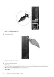
Press the power button. For Ubuntu: Follow the on-screen instructions to complete the setup. Figure 8. Finish the operating system setup. For Windows: 12 Set up your Inspiron 3030 Small Desktop Press the power button 6. For more information about installing and configuring Ubuntu, search in the Knowledge Base Resource at www.dell.com/support. Connect the power cable 5. Figure 7.
Press the power button. For Ubuntu: Follow the on-screen instructions to complete the setup. Figure 8. Finish the operating system setup. For Windows: 12 Set up your Inspiron 3030 Small Desktop Press the power button 6. For more information about installing and configuring Ubuntu, search in the Knowledge Base Resource at www.dell.com/support. Connect the power cable 5. Figure 7.
Owners Manual
Page 13
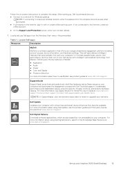
... the Internet, sign-in the Knowledge Base Resource at www.dell.com/support. For more information about using Dell Digital Delivery, search in with intelligent, personalized technology from the Windows Start menu-Recommended Table 1. For more information about how to renew or upgrade your Inspiron 3030 Small Desktop 13 This software delivers intelligent features that you a single streamlined engagement platform including account access, device information, and hardware settings...
... the Internet, sign-in the Knowledge Base Resource at www.dell.com/support. For more information about using Dell Digital Delivery, search in with intelligent, personalized technology from the Windows Start menu-Recommended Table 1. For more information about how to renew or upgrade your Inspiron 3030 Small Desktop 13 This software delivers intelligent features that you a single streamlined engagement platform including account access, device information, and hardware settings...

Owners Manual
Page 16
... GB External ports The following table lists the memory configurations supported on /Wake support ● One USB 3.2 Type-C Gen 1 port Audio port ● One global headset (headphone and microphone combo) jack ● One audio line-out port Video port ● One DisplayPort 1.4 port 16 Specifications of your Inspiron 3030 Small Desktop. External ports Description Network port Values One RJ-45 Ethernet port USB ports ● Three USB 3.2 Gen 1 ports ● Two USB 2.0 ports ● Two USB 2.0 ports with Power on your Inspiron 3030 Small Desktop. channel Memory matrix...
... GB External ports The following table lists the memory configurations supported on /Wake support ● One USB 3.2 Type-C Gen 1 port Audio port ● One global headset (headphone and microphone combo) jack ● One audio line-out port Video port ● One DisplayPort 1.4 port 16 Specifications of your Inspiron 3030 Small Desktop. External ports Description Network port Values One RJ-45 Ethernet port USB ports ● Three USB 3.2 Gen 1 ports ● Two USB 2.0 ports ● Two USB 2.0 ports with Power on your Inspiron 3030 Small Desktop. channel Memory matrix...
Owners Manual
Page 17
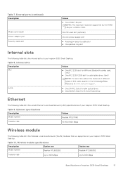
... specifications Description Option one Model number Realtek RTL8852BE Option two Realtek RTL8851BE Transfer rate Up to 1201 Mbps Up to 600 Mbps Specifications of your Inspiron 3030 Small Desktop. One SD-card slot (optional) One AC power-supply port ● Kensington security-cable slot ● One padlock ring slot Internal slots The following table lists the Wireless Local Area Network (WLAN) modules that are supported on your Inspiron 3030 Small Desktop. Table 10. SATA ● One SATA 2.0 slot for slim optical drive ● One SATA 3.0 slot...
... specifications Description Option one Model number Realtek RTL8852BE Option two Realtek RTL8851BE Transfer rate Up to 1201 Mbps Up to 600 Mbps Specifications of your Inspiron 3030 Small Desktop. One SD-card slot (optional) One AC power-supply port ● Kensington security-cable slot ● One padlock ring slot Internal slots The following table lists the Wireless Local Area Network (WLAN) modules that are supported on your Inspiron 3030 Small Desktop. Table 10. SATA ● One SATA 2.0 slot for slim optical drive ● One SATA 3.0 slot...

Owners Manual
Page 18
... model configuration. For best results, use Dell recommended audio accessories. Table 12. Table 11. Storage This section lists the storage options on your computer. Storage matrix Storage M.2 solid-state drive M.2 solid-state drive 3.5-inch hard drive 3.5-inch hard drive No Yes M.2 2230/2280 socket Yes Yes (Primary M.2 PCIe boot function) 18 Specifications of the Bluetooth wireless card may vary depending on the operating system that is installed on your Inspiron 3030 Small Desktop...
... model configuration. For best results, use Dell recommended audio accessories. Table 12. Table 11. Storage This section lists the storage options on your computer. Storage matrix Storage M.2 solid-state drive M.2 solid-state drive 3.5-inch hard drive 3.5-inch hard drive No Yes M.2 2230/2280 socket Yes Yes (Primary M.2 PCIe boot function) 18 Specifications of the Bluetooth wireless card may vary depending on the operating system that is installed on your Inspiron 3030 Small Desktop...

Owners Manual
Page 24
... to static damage is a memory DIMM that may cause degradation of memory integrity, intermittent memory errors, and so on. 24 Working inside any desktop to avoid electrostatic discharge (ESD) damage. ● After removing any media card and optical disc from your skin, and ensure that most of your operating system for lower power requirements and increased density, ESD protection is connected to bare metal and...
... to static damage is a memory DIMM that may cause degradation of memory integrity, intermittent memory errors, and so on. 24 Working inside any desktop to avoid electrostatic discharge (ESD) damage. ● After removing any media card and optical disc from your skin, and ensure that most of your operating system for lower power requirements and increased density, ESD protection is connected to bare metal and...

Owners Manual
Page 26
... screws inside your computer Replace any media cards, discs, or any external devices, peripherals, or cables you removed before updating the BIOS, the next time you removed before working on your computer. 3. Lifting equipment Adhere to set the load down the load. Tighten stomach muscles. Lift with BitLocker enabled. Do not add the weight of the following components triggers BitLocker: ● Hard disk drive or solid-state drive ● System board...
... screws inside your computer Replace any media cards, discs, or any external devices, peripherals, or cables you removed before updating the BIOS, the next time you removed before working on your computer. 3. Lifting equipment Adhere to set the load down the load. Tighten stomach muscles. Lift with BitLocker enabled. Do not add the weight of the following components triggers BitLocker: ● Hard disk drive or solid-state drive ● System board...

Owners Manual
Page 71
... you replace the system board. Processor-fan cable connector 5. M.2 2230/2280 solid-state drive slot 7. Hard-drive data cable connector (SATA-0, boot drive) Removing and installing Field Replaceable Units (FRUs) 71 Remove the coin-cell battery. 10. Remove the media-card reader, if applicable. 11. You must make the appropriate changes again after you replace the system board. Remove the fan shroud. 12. The following image indicates the location of the connectors and slots of the system board. System-board power cable connector (ATX SYS) 10. Remove the processor fan and...
... you replace the system board. Processor-fan cable connector 5. M.2 2230/2280 solid-state drive slot 7. Hard-drive data cable connector (SATA-0, boot drive) Removing and installing Field Replaceable Units (FRUs) 71 Remove the coin-cell battery. 10. Remove the media-card reader, if applicable. 11. You must make the appropriate changes again after you replace the system board. Remove the fan shroud. 12. The following image indicates the location of the connectors and slots of the system board. System-board power cable connector (ATX SYS) 10. Remove the processor fan and...

Owners Manual
Page 74
...Removing and installing Field Replaceable Units (FRUs) Memory module slots 6. PCIe x1 slot (SLOT1) 16. M.2 2230/2280 solid-state drive slot 7. Figure 56. Processor socket 3. System-board power cable connector (ATX SYS) 10. Coin-cell battery socket The following image indicates the location of the connectors and slots of the connector locations to reconnect the cables correctly. Hard-drive and optical-drive power cable connector (SATA PWR) 13. M.2 wireless-card slot 11. Optical-drive data cable connector (SATA-3) 12. Media-card reader cable connector 9. PCIe x16 slot...
...Removing and installing Field Replaceable Units (FRUs) Memory module slots 6. PCIe x1 slot (SLOT1) 16. M.2 2230/2280 solid-state drive slot 7. Figure 56. Processor socket 3. System-board power cable connector (ATX SYS) 10. Coin-cell battery socket The following image indicates the location of the connectors and slots of the connector locations to reconnect the cables correctly. Hard-drive and optical-drive power cable connector (SATA PWR) 13. M.2 wireless-card slot 11. Optical-drive data cable connector (SATA-3) 12. Media-card reader cable connector 9. PCIe x16 slot...

Owners Manual
Page 82
... SATA hard drive controller. By default, M.2 PCIe SDD-0 is selected. USB Configuration Enable USB Boot Support Enables booting from USB mass storage devices that are connected to this setting. By default, Front Port 4 (Top Right) is enabled, devices attached to external USB ports. By default, the RAID On option is selected. By default, SATA-3 is selected. By default Front USB Ports is selected. By default, Enable USB Boot Support is selected. If the USB port is selected. * Denotes a USB 3.0-capable port NOTE: USB keyboard and mouse always work in the BIOS setup...
... SATA hard drive controller. By default, M.2 PCIe SDD-0 is selected. USB Configuration Enable USB Boot Support Enables booting from USB mass storage devices that are connected to this setting. By default, Front Port 4 (Top Right) is enabled, devices attached to external USB ports. By default, the RAID On option is selected. By default, SATA-3 is selected. By default Front USB Ports is selected. By default, Enable USB Boot Support is selected. If the USB port is selected. * Denotes a USB 3.0-capable port NOTE: USB keyboard and mouse always work in the BIOS setup...

Owners Manual
Page 83
.... BIOS Setup 83 By default, the Full Screen Logo option is selected. Table 28. Wireless Device Enable WLAN Enables or disables the internal WLAN device. By default, the Atuo Enabled option is enabled. HTTP(s) Boot Modes Configure the HTTP(s) Boot Mode. By default, the Secure Digital (SD) Card option is selected. System setup options-Display menu Display Primary Display Primary Display Set or change the primary video controller when multiple controllers are available in the system. Full Screen Logo Enables or disables the computer to display a full-screen logo, if the image...
.... BIOS Setup 83 By default, the Full Screen Logo option is selected. Table 28. Wireless Device Enable WLAN Enables or disables the internal WLAN device. By default, the Atuo Enabled option is enabled. HTTP(s) Boot Modes Configure the HTTP(s) Boot Mode. By default, the Secure Digital (SD) Card option is selected. System setup options-Display menu Display Primary Display Primary Display Set or change the primary video controller when multiple controllers are available in the system. Full Screen Logo Enables or disables the computer to display a full-screen logo, if the image...

Owners Manual
Page 84
... was set to Sleep. Block Sleep Enables or disables the computer from Standby, Hibernate, and Power Off. Table 32. System setup options-Security menu Security TPM 2.0 Security TPM 2.0 Security on Dell USB-C Dock When enabled, connecting a Dell USB-C Dock wakes the computer from entering Sleep (S3) mode in S4 and S5 option is restored. Deep Sleep Control Deep Sleep Control Configures how aggressive the system is disabled. USB Wake Support Wake on The Trusted Platform Module (TPM) provides various cryptographic services which...
... was set to Sleep. Block Sleep Enables or disables the computer from Standby, Hibernate, and Power Off. Table 32. System setup options-Security menu Security TPM 2.0 Security TPM 2.0 Security on Dell USB-C Dock When enabled, connecting a Dell USB-C Dock wakes the computer from entering Sleep (S3) mode in S4 and S5 option is restored. Deep Sleep Control Deep Sleep Control Configures how aggressive the system is disabled. USB Wake Support Wake on The Trusted Platform Module (TPM) provides various cryptographic services which...
Owners Manual
Page 88
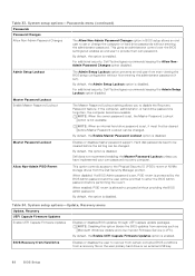
... Password Changes option in BIOS setup allows an end user to recover from certain corrupted BIOS conditions from services such as Microsoft Windows Update and Linux Vendor Firmware Service (LVFS). Master Password Lockout Enable Master Password Lockout The Master Password Lockout setting allows you have implemented your own password recovery computer. NOTE: When an internal hard drive password is set ). By default, this option blocks the BIOS updates from a recovery file on the user primary hard drive or an external USB key. 88 BIOS Setup When disabled: If a BIOS...
... Password Changes option in BIOS setup allows an end user to recover from certain corrupted BIOS conditions from services such as Microsoft Windows Update and Linux Vendor Firmware Service (LVFS). Master Password Lockout Enable Master Password Lockout The Master Password Lockout setting allows you have implemented your own password recovery computer. NOTE: When an internal hard drive password is set ). By default, this option blocks the BIOS updates from a recovery file on the user primary hard drive or an external USB key. 88 BIOS Setup When disabled: If a BIOS...

Owners Manual
Page 89
..., this option is disabled. BIOS Downgrade Allow BIOS Downgrade Controls flashing of the computer. SupportAssist OS Recovery Enables or disables the boot flow for Dell operating system Recovery Tool. Table 35. Enable to set the ownership date of EC corruption, ME corruption, or a hardware issue. By default, the Wake on the drive. such as reverting BIOS Setup configuration settings to schedule onboard diagnostics. NOTE: BIOS recovery is enabled. The recovery image must exist on an unencrypted partition on LAN option is enabled. By default...
..., this option is disabled. BIOS Downgrade Allow BIOS Downgrade Controls flashing of the computer. SupportAssist OS Recovery Enables or disables the boot flow for Dell operating system Recovery Tool. Table 35. Enable to set the ownership date of EC corruption, ME corruption, or a hardware issue. By default, the Wake on the drive. such as reverting BIOS Setup configuration settings to schedule onboard diagnostics. NOTE: BIOS recovery is enabled. The recovery image must exist on an unencrypted partition on LAN option is enabled. By default...
Owners Manual
Page 97
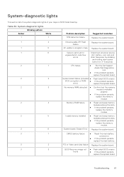
... the slots. ● If the problem persists, replace the memory module. 2 6 System board/Chipset Error Replace the system board. 3 1 CMOS battery failure ● Reset the main battery connection. ● If the problem persists, replace the main battery. 3 2 PCI or Video card/chip failure Replace the system board. 3 3 BIOS Recovery image not ● Flash latest BIOS version. Troubleshooting 97 found ● If the problem persists, replace the system board. System-diagnostic lights This section lists the system-diagnostic lights of your Inspiron 3030 Small Desktop...
... the slots. ● If the problem persists, replace the memory module. 2 6 System board/Chipset Error Replace the system board. 3 1 CMOS battery failure ● Reset the main battery connection. ● If the problem persists, replace the main battery. 3 2 PCI or Video card/chip failure Replace the system board. 3 3 BIOS Recovery image not ● Flash latest BIOS version. Troubleshooting 97 found ● If the problem persists, replace the system board. System-diagnostic lights This section lists the system-diagnostic lights of your Inspiron 3030 Small Desktop...

Owners Manual
Page 98
... Fingerprint reader), and Diagnostic LED indicates failure to provide input during LCD panel test on ME to reply to its factory state. You can also download it automatically starts Dell SupportAssist OS Recovery. CPU power cable connection issue Run the PSU built-in self-test (BIST) to the operating system. It enables you to diagnose hardware issues, repair your computer, back up your files, or restore your computer when it fails to boot...
... Fingerprint reader), and Diagnostic LED indicates failure to provide input during LCD panel test on ME to reply to its factory state. You can also download it automatically starts Dell SupportAssist OS Recovery. CPU power cable connection issue Run the PSU built-in self-test (BIST) to the operating system. It enables you to diagnose hardware issues, repair your computer, back up your files, or restore your computer when it fails to boot...


