Setup and Specifications
Page 10
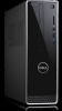
... a standard padlock to prevent unauthorized access to the interior of your computer. 10 Views of Inspiron 3470 The two lights next to the connector indicate the connectivity status and network activity. 8 Service... Tag label The Service Tag is a unique alphanumeric identifier that enables Dell service technicians to identify the hardware components in your computer and access warranty information. 9 ...projector. 5 HDMI port Connect to your computer. 11 Power-supply diagnostics light Indicates the power-supply state. 12 Security-cable slot (for network or Internet access.
... a standard padlock to prevent unauthorized access to the interior of your computer. 10 Views of Inspiron 3470 The two lights next to the connector indicate the connectivity status and network activity. 8 Service... Tag label The Service Tag is a unique alphanumeric identifier that enables Dell service technicians to identify the hardware components in your computer and access warranty information. 9 ...projector. 5 HDMI port Connect to your computer. 11 Power-supply diagnostics light Indicates the power-supply state. 12 Security-cable slot (for network or Internet access.

Service Manual
Page 5
... modules...45 Procedure...45 Post-requisites...45 26 Removing the power-button module...46 Prerequisites...46 Procedure...46 27 Replacing the power-button module...48 Procedure...48 Post-requisites...49 28 Removing the power-supply unit...50 Prerequisites...50 Procedure...50 29 Replacing the power-supply unit...52 Procedure...52 Post-requisites...53 30 Removing the...
... modules...45 Procedure...45 Post-requisites...45 26 Removing the power-button module...46 Prerequisites...46 Procedure...46 27 Replacing the power-button module...48 Procedure...48 Post-requisites...49 28 Removing the power-supply unit...50 Prerequisites...50 Procedure...50 29 Replacing the power-supply unit...52 Procedure...52 Post-requisites...53 30 Removing the...

Service Manual
Page 8
Screw list Component Computer cover 2.5-inch hard drive 2.5-inch hard drive 3.5-inch hard drive 3.5-inch hard drive Drive cage Optical drive Wireless card Power-supply unit Front-I/O bracket System board Secured to Chassis Drive cage Hard-drive bracket Drive cage Hard-drive bracket Chassis Optical-drive bracket System board Chassis ...
Screw list Component Computer cover 2.5-inch hard drive 2.5-inch hard drive 3.5-inch hard drive 3.5-inch hard drive Drive cage Optical drive Wireless card Power-supply unit Front-I/O bracket System board Secured to Chassis Drive cage Hard-drive bracket Drive cage Hard-drive bracket Chassis Optical-drive bracket System board Chassis ...

Service Manual
Page 10
..., see the Regulatory Compliance home page at www.dell.com/ regulatory_compliance. Topics: • Inside view of your computer • System board components Inside view of your computer 1 memory modules 3 processor fan and heat-sink assembly 5 drive cage 2 system board 4 hard-drive assembly 6 power-supply unit 10 Technical overview After working inside your computer...
..., see the Regulatory Compliance home page at www.dell.com/ regulatory_compliance. Topics: • Inside view of your computer • System board components Inside view of your computer 1 memory modules 3 processor fan and heat-sink assembly 5 drive cage 2 system board 4 hard-drive assembly 6 power-supply unit 10 Technical overview After working inside your computer...

Service Manual
Page 11
... x1 card slot (SLOT1) 9 password clear jumper 11 solid-state drive slot (M.2 SSD) 13 processor power connector (ATX_CPU) 15 hard-drive data cable connector (SATA3) 17 hard drive and optical-drive power cable connector 2 coin-cell battery 4 power-supply unit cable connector (ATX_SYS) 6 PCI-Express x16 card slot (SLOT2) 8 service mode jumper 10 CMOS...
... x1 card slot (SLOT1) 9 password clear jumper 11 solid-state drive slot (M.2 SSD) 13 processor power connector (ATX_CPU) 15 hard-drive data cable connector (SATA3) 17 hard drive and optical-drive power cable connector 2 coin-cell battery 4 power-supply unit cable connector (ATX_SYS) 6 PCI-Express x16 card slot (SLOT2) 8 service mode jumper 10 CMOS...

Service Manual
Page 50
... safety best practices, see the Regulatory Compliance home page at www.dell.com/ regulatory_compliance. 28 Removing the power-supply unit WARNING: Before working inside your computer, read the safety information that secure the power-supply unit to the chassis. 5 Press the clamp and slide the power-supply unit towards the front of the chassis to step 6 in...
... safety best practices, see the Regulatory Compliance home page at www.dell.com/ regulatory_compliance. 28 Removing the power-supply unit WARNING: Before working inside your computer, read the safety information that secure the power-supply unit to the chassis. 5 Press the clamp and slide the power-supply unit towards the front of the chassis to step 6 in...

Service Manual
Page 51
Removing the power-supply unit 51 6 Lift the power-supply unit, along with the cables, off the chassis.
Removing the power-supply unit 51 6 Lift the power-supply unit, along with the cables, off the chassis.

Service Manual
Page 52
...safety best practices, see the Regulatory Compliance home page at www.dell.com/ regulatory_compliance. Topics: • Procedure • Post-requisites Procedure 1 Place the power-supply unit on the chassis. 2 Slide the power-supply unit towards the back of the chassis until it snaps into place...(#6-32xL6.35) that secure the power-supply unit to the chassis. 5 Route the power-supply unit cable through the routing guides inside the chassis. 6 Connect the power-supply unit cables (ATX_CPU and ATX_SYS) to the system board. 52 Replacing the power-supply unit After working inside your computer...
...safety best practices, see the Regulatory Compliance home page at www.dell.com/ regulatory_compliance. Topics: • Procedure • Post-requisites Procedure 1 Place the power-supply unit on the chassis. 2 Slide the power-supply unit towards the back of the chassis until it snaps into place...(#6-32xL6.35) that secure the power-supply unit to the chassis. 5 Route the power-supply unit cable through the routing guides inside the chassis. 6 Connect the power-supply unit cables (ATX_CPU and ATX_SYS) to the system board. 52 Replacing the power-supply unit After working inside your computer...

Service Manual
Page 53
Replacing the power-supply unit 53 Post-requisites 1 Follow the procedure from step 5 to step 8 in "Replacing the optical drive". 2 Replace the front bezel. 3 Replace the computer cover.
Replacing the power-supply unit 53 Post-requisites 1 Follow the procedure from step 5 to step 8 in "Replacing the optical drive". 2 Replace the front bezel. 3 Replace the computer cover.

Service Manual
Page 59
...cable from the system board. 4 Disconnect the power-supply unit cable from the system board. 5 Disconnect the hard-drive data cable from the system board. 6 Disconnect the hard drive and optical-drive power cable from the system board. 7 Disconnect the power-button module from the system board. 8 ...Disconnect the processor power-cable from the system board and remove the processor power-cable from the routing guides on the chassis. 9 Remove...
...cable from the system board. 4 Disconnect the power-supply unit cable from the system board. 5 Disconnect the hard-drive data cable from the system board. 6 Disconnect the hard drive and optical-drive power cable from the system board. 7 Disconnect the power-button module from the system board. 8 ...Disconnect the processor power-cable from the system board and remove the processor power-cable from the routing guides on the chassis. 9 Remove...

Service Manual
Page 61
...the instructions in the system board. Replacing the system board 61 For more safety best practices, see the Regulatory Compliance home page at www.dell.com/ regulatory_compliance. 35 Replacing the system board WARNING: Before working inside your computer, read the safety information that shipped with the slots on... (#6-32xL6.35) that secure the system board to the chassis. 3 Connect the optical-drive data cable to the system board. 4 Connect the power-supply unit cable to the system board. 5 Connect the hard-drive data cable to the BIOS using the BIOS setup program. You must make the ...
...the instructions in the system board. Replacing the system board 61 For more safety best practices, see the Regulatory Compliance home page at www.dell.com/ regulatory_compliance. 35 Replacing the system board WARNING: Before working inside your computer, read the safety information that shipped with the slots on... (#6-32xL6.35) that secure the system board to the chassis. 3 Connect the optical-drive data cable to the system board. 4 Connect the power-supply unit cable to the system board. 5 Connect the hard-drive data cable to the BIOS using the BIOS setup program. You must make the ...

Service Manual
Page 70
... Main System Time System Date BIOS Version Product Name Service Tag Asset Tag CPU Type CPU Speed CPU ID Cache L1 Cache L2 First HDD Power supply unit System Memory Memory Speed Displays the current time in mm/dd/yyyy format. Displays the current date in hh:mm:ss format. Displays the...
... Main System Time System Date BIOS Version Product Name Service Tag Asset Tag CPU Type CPU Speed CPU ID Cache L1 Cache L2 First HDD Power supply unit System Memory Memory Speed Displays the current time in mm/dd/yyyy format. Displays the current date in hh:mm:ss format. Displays the...


