Dell™ Technology Guide
Page 11
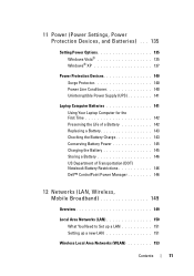
... Uninterruptible Power Supply (UPS 141 Laptop Computer Batteries 141 Using Your Laptop Computer for the First Time 142 Preserving the Life of a Battery 142 Replacing a Battery 143 Checking the Battery Charge 143 Conserving Battery Power 145 Charging the Battery 145 Storing a Battery 146 US Department of Transportation (DOT) Notebook Battery Restrictions 146 Dell™ ControlPoint Power...
... Uninterruptible Power Supply (UPS 141 Laptop Computer Batteries 141 Using Your Laptop Computer for the First Time 142 Preserving the Life of a Battery 142 Replacing a Battery 143 Checking the Battery Charge 143 Conserving Battery Power 145 Charging the Battery 145 Storing a Battery 146 US Department of Transportation (DOT) Notebook Battery Restrictions 146 Dell™ ControlPoint Power...

Dell™ Technology Guide
Page 279
... A G E S . - IT IS ADVISABLE TO IMMEDIATELY BACK UP YOUR DATA AND REPLACE YOUR HARD DRIVE BY CALLING YOUR SUPPORT DESK OR D E L L. - Contact Dell for assistance (see "Contacting Dell" on page 337). Connect the correct AC adapter. THE RECOMMENDED XXX-W AC ADAPTER ORIGINALLY ... THE BATTERY ATTACHED CANNOT POWER THE SYSTEM. WA R N I N G : T H E T P M C O U L D N O T B E I N I T I A L I S R E M O V E D . - YOUR POWER ADAPTER DOES NOT SUPPLY ENOUGH POWER TO RUN THE ATTACHED DOCKING STATION. THEY SYSTEM WILL ADJUST THE PERFORMANCE TO MATCH THE POWER AVAILABLE. System board failure ...
... A G E S . - IT IS ADVISABLE TO IMMEDIATELY BACK UP YOUR DATA AND REPLACE YOUR HARD DRIVE BY CALLING YOUR SUPPORT DESK OR D E L L. - Contact Dell for assistance (see "Contacting Dell" on page 337). Connect the correct AC adapter. THE RECOMMENDED XXX-W AC ADAPTER ORIGINALLY ... THE BATTERY ATTACHED CANNOT POWER THE SYSTEM. WA R N I N G : T H E T P M C O U L D N O T B E I N I T I A L I S R E M O V E D . - YOUR POWER ADAPTER DOES NOT SUPPLY ENOUGH POWER TO RUN THE ATTACHED DOCKING STATION. THEY SYSTEM WILL ADJUST THE PERFORMANCE TO MATCH THE POWER AVAILABLE. System board failure ...

Owner's Manual
Page 8
Inspiron 530sc 115 Inspiron 530sd 117 Power Supply DC Connector Pin Assignments 119 Memory 123 Memory Installation Guidelines 123 Installing Memory 125 Removing Memory 127 Cards 128 PCI and PCI Express Cards 128 Bezel 135 Removing the Bezel 135 Replacing the Bezel 136 Drives 137 Recommended Drive Cable Connections 137 Connecting Drive Cables 138 Drive Interface...
Inspiron 530sc 115 Inspiron 530sd 117 Power Supply DC Connector Pin Assignments 119 Memory 123 Memory Installation Guidelines 123 Installing Memory 125 Removing Memory 127 Cards 128 PCI and PCI Express Cards 128 Bezel 135 Removing the Bezel 135 Replacing the Bezel 136 Drives 137 Recommended Drive Cable Connections 137 Connecting Drive Cables 138 Drive Interface...

Owner's Manual
Page 159
... on page 154). 6 Remove the hard drive power cable, CD/DVD drive data and power cable, front panel cable, and any other cables from the system board and drives. Removing and Installing Parts 159 Power Supply CAUTION: Before you replace them to prevent them from the securing clip on ...the side of the power supply. 7 Remove the three screws that attach the power supply to the back of the computer chassis. NOTICE: To prevent...
... on page 154). 6 Remove the hard drive power cable, CD/DVD drive data and power cable, front panel cable, and any other cables from the system board and drives. Removing and Installing Parts 159 Power Supply CAUTION: Before you replace them to prevent them from the securing clip on ...the side of the power supply. 7 Remove the three screws that attach the power supply to the back of the computer chassis. NOTICE: To prevent...

Owner's Manual
Page 160
... of the system grounding. NOTE: Double-check all screws may cause electrical shock as these screws are secure. 14 Replace the support bracket (see "Replacing the Support Bracket" on the side of the power supply. CAUTION: Failure to the securing clip on page 173). 160 Removing and Installing Parts The cables must be properly...
... of the system grounding. NOTE: Double-check all screws may cause electrical shock as these screws are secure. 14 Replace the support bracket (see "Replacing the Support Bracket" on the side of the power supply. CAUTION: Failure to the securing clip on page 173). 160 Removing and Installing Parts The cables must be properly...

Owner's Manual
Page 161
...them on. 17 Verify that you can do so by touching an unpainted metal surface on the computer chassis. 15 Replace the computer cover (see "Replacing the Computer Cover" on page 174). 16 Connect your computer and devices to cool before you touch them. Removing... Guide. CAUTION: To guard against likelihood of electric shock, laceration by running the Dell Diagnostics (see "Dell Diagnostics" on page 88). Carelessness may be extremely careful. CAUTION: The heat sink assembly, power supply, and other unexpected injuries, always unplug your body before opening the cover. NOTICE:...
...them on. 17 Verify that you can do so by touching an unpainted metal surface on the computer chassis. 15 Replace the computer cover (see "Replacing the Computer Cover" on page 174). 16 Connect your computer and devices to cool before you touch them. Removing... Guide. CAUTION: To guard against likelihood of electric shock, laceration by running the Dell Diagnostics (see "Dell Diagnostics" on page 88). Carelessness may be extremely careful. CAUTION: The heat sink assembly, power supply, and other unexpected injuries, always unplug your body before opening the cover. NOTICE:...

Owner's Manual
Page 170
Replacing the Chassis Fan 1 Follow the procedures in "Before You Begin" on page 103. 1 1 screw 2 Remove the computer cover (see "Removing the Computer Cover" on page ... Removing the System Board CAUTION: To guard against likelihood of the computer. 4 Tighten the screw to secure the chassis fan. CAUTION: The heat sink assembly, power supply, and other unexpected injuries, always unplug your computer, ground yourself by moving fan blades or other components may be very hot during normal operation. NOTICE...
Replacing the Chassis Fan 1 Follow the procedures in "Before You Begin" on page 103. 1 1 screw 2 Remove the computer cover (see "Removing the Computer Cover" on page ... Removing the System Board CAUTION: To guard against likelihood of the computer. 4 Tighten the screw to secure the chassis fan. CAUTION: The heat sink assembly, power supply, and other unexpected injuries, always unplug your computer, ground yourself by moving fan blades or other components may be very hot during normal operation. NOTICE...


