
Setup and Specifications
Page 4
... the Windows Start menu-Recommended. NOTE: To conserve battery power, the battery might enter power saving mode. Locate and use Dell apps from your computer depending on -screen instructions to a secured wireless network, enter the password for your computer. The SupportAssist OS Recovery tool troubleshoots issues with Dell. Connect the power adapter and press the power button. NOTE: If connecting to complete the setup. Table 1. SupportAssist Proactively checks the health of your Inspiron 5593 For more information about installing and configuring Ubuntu...
... the Windows Start menu-Recommended. NOTE: To conserve battery power, the battery might enter power saving mode. Locate and use Dell apps from your computer depending on -screen instructions to a secured wireless network, enter the password for your computer. The SupportAssist OS Recovery tool troubleshoots issues with Dell. Connect the power adapter and press the power button. NOTE: If connecting to complete the setup. Table 1. SupportAssist Proactively checks the health of your Inspiron 5593 For more information about installing and configuring Ubuntu...
Setup and Specifications
Page 6
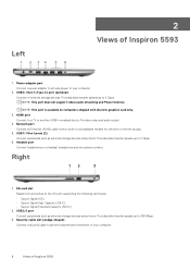
...-adapter port Connect a power adapter to provide power to 5 Gbps. Headset port Connect headphones or a headset (headphone and microphone combo). Security-cable slot (wedge-shaped) Connect a security cable to the SD card, supporting the following card types: • Secure Digital (SD) • Secure Digital High Capacity (SDHC) • Secure Digital Extended Capacity (SDXC) 2. Provides video and audio output. 4. 2 Views of Inspiron 5593 USB 3.1 Gen 1 (Type-C) port (optional) Connect to 5 Gbps. 6. USB 3.1 Gen 1 ports (2) Connect peripherals such as external storage devices...
...-adapter port Connect a power adapter to provide power to 5 Gbps. Headset port Connect headphones or a headset (headphone and microphone combo). Security-cable slot (wedge-shaped) Connect a security cable to the SD card, supporting the following card types: • Secure Digital (SD) • Secure Digital High Capacity (SDHC) • Secure Digital Extended Capacity (SDXC) 2. Provides video and audio output. 4. 2 Views of Inspiron 5593 USB 3.1 Gen 1 (Type-C) port (optional) Connect to 5 Gbps. 6. USB 3.1 Gen 1 ports (2) Connect peripherals such as external storage devices...

Setup and Specifications
Page 12
... Internal ports and connectors Description Internal: M.2 Communications Values One headset (headphone and microphone combo) port One HDMI port NOTE: The maximum resolution supported by this HDMI port is 1920x1080. Ethernet Table 11. Ethernet specifications Description Model number Transfer rate Values Ethernet controller integrated on the system board 10/100 Mbps Wireless module Table 12. External ports and connectors(continued) Description Audio Video Media card reader Docking port Power adapter port Security Table 10. Wireless module specifications Description Values Model number...
... Internal ports and connectors Description Internal: M.2 Communications Values One headset (headphone and microphone combo) port One HDMI port NOTE: The maximum resolution supported by this HDMI port is 1920x1080. Ethernet Table 11. Ethernet specifications Description Model number Transfer rate Values Ethernet controller integrated on the system board 10/100 Mbps Wireless module Table 12. External ports and connectors(continued) Description Audio Video Media card reader Docking port Power adapter port Security Table 10. Wireless module specifications Description Values Model number...
Service Manual
Page 3
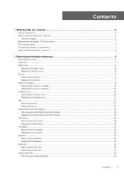
... protection...7 ESD field service kit ...7 Transporting sensitive components...8 After working inside your computer...8 2 Removing and installing components 9 Recommended tools...9 Screw list...9 Base cover...10 Removing the base cover...10 Replacing the base cover...13 Battery...16 Removing the battery...16 Replacing the battery...17 Memory modules...19 Removing the memory modules...19 Replacing the memory modules...20 Wireless card...20 Removing the wireless card...20 Replacing the wireless card...21 Fan...22 Removing the fan...22 Replacing the fan...23 Solid-state drive/Intel Optane...24...
... protection...7 ESD field service kit ...7 Transporting sensitive components...8 After working inside your computer...8 2 Removing and installing components 9 Recommended tools...9 Screw list...9 Base cover...10 Removing the base cover...10 Replacing the base cover...13 Battery...16 Removing the battery...16 Replacing the battery...17 Memory modules...19 Removing the memory modules...19 Replacing the memory modules...20 Wireless card...20 Removing the wireless card...20 Replacing the wireless card...21 Fan...22 Removing the fan...22 Replacing the fan...23 Solid-state drive/Intel Optane...24...
Service Manual
Page 4
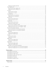
... camera...62 Replacing the camera...63 Display panel...64 Removing the display panel...64 Replacing the display panel...66 Display cable...68 Removing the display cable...68 Replacing the display cable...69 Display back-cover and antenna assembly...70 Removing the display back-cover and antenna assembly 70 Replacing the display back-cover and antenna assembly 71 3 Device drivers...73 Downloading the audio driver...73 Downloading the network driver...73 Downloading the chipset driver...74 Downloading the media-card reader driver...74 Downloading the WiFi driver...75 Downloading the USB driver...
... camera...62 Replacing the camera...63 Display panel...64 Removing the display panel...64 Replacing the display panel...66 Display cable...68 Removing the display cable...68 Replacing the display cable...69 Display back-cover and antenna assembly...70 Removing the display back-cover and antenna assembly 70 Replacing the display back-cover and antenna assembly 71 3 Device drivers...73 Downloading the audio driver...73 Downloading the network driver...73 Downloading the chipset driver...74 Downloading the media-card reader driver...74 Downloading the WiFi driver...75 Downloading the USB driver...
Service Manual
Page 6
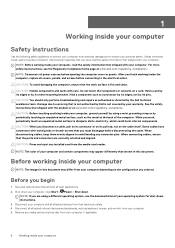
... only perform troubleshooting and repairs as a processor by its edges, not by periodically touching an unpainted metal surface, such as keyboard, mouse, and monitor from your computer CAUTION: Press and eject any connector pins. Disconnect all attached network devices and peripherals, such as the metal at www.dell.com/regulatory_compliance. Remove any media card and optical disc from your computer, if applicable. 6 Working inside...
... only perform troubleshooting and repairs as a processor by its edges, not by periodically touching an unpainted metal surface, such as keyboard, mouse, and monitor from your computer CAUTION: Press and eject any connector pins. Disconnect all attached network devices and peripherals, such as the metal at www.dell.com/regulatory_compliance. Remove any media card and optical disc from your computer, if applicable. 6 Working inside...
Service Manual
Page 7
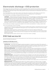
... the system, or inside of semiconductors used service kit. The use wireless wrist straps. Touching the chassis before handling parts does not ensure adequate ESD protection on the ESD mat, in recent Dell products, the sensitivity to avoid accidental ESD hardware damage. a red LED is successful; For example, deploying the kit for a large open flat work area, insulators such as bonding...
... the system, or inside of semiconductors used service kit. The use wireless wrist straps. Touching the chassis before handling parts does not ensure adequate ESD protection on the ESD mat, in recent Dell products, the sensitivity to avoid accidental ESD hardware damage. a red LED is successful; For example, deploying the kit for a large open flat work area, insulators such as bonding...
Service Manual
Page 8
... in . Connect any external devices, peripherals, or cables you removed before working on your computer. 8 Working inside your computer Connect your computer and all attached devices to the load. All ESD-sensitive devices must be used in the original box that the new part arrived in reverse to set the load down the load. When transporting ESD sensitive components such as replacement parts or parts to be...
... in . Connect any external devices, peripherals, or cables you removed before working on your computer. 8 Working inside your computer Connect your computer and all attached devices to the load. All ESD-sensitive devices must be used in the original box that the new part arrived in reverse to set the load down the load. When transporting ESD sensitive components such as replacement parts or parts to be...

Service Manual
Page 19
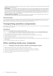
Prerequisites Remove the base cover. Procedure 1. Removing and installing components 19 Post-requisites Replace the base cover. After working inside your computer, follow the steps in After working inside your computer. Use your fingertips to carefully spread apart the securing-clips on your computer. 2. Locate the memory module on each end of the memory-module slot until the memory module pops up. 3. Remove the memory module from the memory-module slot. For more safety best...
Prerequisites Remove the base cover. Procedure 1. Removing and installing components 19 Post-requisites Replace the base cover. After working inside your computer, follow the steps in After working inside your computer. Use your fingertips to carefully spread apart the securing-clips on your computer. 2. Locate the memory module on each end of the memory-module slot until the memory module pops up. 3. Remove the memory module from the memory-module slot. For more safety best...
Service Manual
Page 20
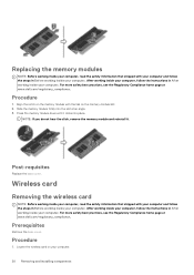
... the memory module with the tab on your computer. Prerequisites Remove the base cover. Locate the wireless card on the memory-module slot. 2. After working inside your computer, follow the instructions in After working inside your computer. 20 Removing and installing components NOTE: If you do not hear the click, remove the memory module and reinstall it clicks into the slot at www.dell.com/regulatory_compliance. Wireless card Removing the wireless card NOTE: Before working inside...
... the memory module with the tab on your computer. Prerequisites Remove the base cover. Locate the wireless card on the memory-module slot. 2. After working inside your computer, follow the instructions in After working inside your computer. 20 Removing and installing components NOTE: If you do not hear the click, remove the memory module and reinstall it clicks into the slot at www.dell.com/regulatory_compliance. Wireless card Removing the wireless card NOTE: Before working inside...
Service Manual
Page 45
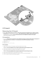
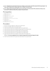
...-cell battery resets the BIOS setup program's settings to note the BIOS setup program's settings. 1. Open the latch and disconnect the fingerprint-reader cable from the I /O board along with the coin-cell battery, it is applicable only for computers shipped with the optional fingerprint reader. 2. Lift the I /O board. After working inside your computer, follow the steps in After working inside your computer. Before removing the I /O board. 3. Remove the base cover. 2. Remove the battery. 3. Remove the hard drive...
...-cell battery resets the BIOS setup program's settings to note the BIOS setup program's settings. 1. Open the latch and disconnect the fingerprint-reader cable from the I /O board along with the coin-cell battery, it is applicable only for computers shipped with the optional fingerprint reader. 2. Lift the I /O board. After working inside your computer, follow the steps in After working inside your computer. Before removing the I /O board. 3. Remove the base cover. 2. Remove the battery. 3. Remove the hard drive...
Service Manual
Page 51
... the power-adapter port cable from the system board. 6. Open the latch and disconnect the touchpad cable from the system board. 2. Removing and installing components 51 Remove the wireless card. 5. Remove the heat sink. 8. Open the latch and disconnect the fingerprint-reader cable from the system board. 7. Remove the base cover. 2. Remove the display assembly. Open the latch and disconnect the hard-drive cable from the system board. Remove the memory modules. 4. Remove the battery. 3. Open the latch and disconnect the power-button board cable from the system board. 4. Open...
... the power-adapter port cable from the system board. 6. Open the latch and disconnect the touchpad cable from the system board. 2. Removing and installing components 51 Remove the wireless card. 5. Remove the heat sink. 8. Open the latch and disconnect the fingerprint-reader cable from the system board. 7. Remove the base cover. 2. Remove the display assembly. Open the latch and disconnect the hard-drive cable from the system board. Remove the memory modules. 4. Remove the battery. 3. Open the latch and disconnect the power-button board cable from the system board. 4. Open...

Service Manual
Page 73
... Drivers button. 6. NOTE: Review on your computer model. 4. Review and agree to the Terms and Conditions to make changes on your computer. 10. Turn on -screen instructions for your computer starts to make changes on the system. 12. Click the Detect Drivers button. 6. Click View Drivers for My System. 9. If prompted, approve requests from User Account Control to download and install SupportAssist. NOTE: If you do not have the Service Tag, use...
... Drivers button. 6. NOTE: Review on your computer model. 4. Review and agree to the Terms and Conditions to make changes on your computer. 10. Turn on -screen instructions for your computer starts to make changes on the system. 12. Click the Detect Drivers button. 6. Click View Drivers for My System. 9. If prompted, approve requests from User Account Control to download and install SupportAssist. NOTE: If you do not have the Service Tag, use...

Service Manual
Page 74
... the Service Tag, use the auto-detect feature or manually browse for browser-specific instructions. 8. Click the Detect Drivers button. 6. NOTE: Review on-screen instructions for your computer. 10. If prompted, approve requests from User Account Control to install the driver. For manual download and installation, click Category. 14. Click Network in the drop-down list. 15. Double-click the network driver file icon and follow the instructions on the screen to make changes on...
... the Service Tag, use the auto-detect feature or manually browse for browser-specific instructions. 8. Click the Detect Drivers button. 6. NOTE: Review on-screen instructions for your computer. 10. If prompted, approve requests from User Account Control to install the driver. For manual download and installation, click Category. 14. Click Network in the drop-down list. 15. Double-click the network driver file icon and follow the instructions on the screen to make changes on...

Service Manual
Page 75
... Terms and Conditions to install the driver. If prompted, approve requests from User Account Control to make changes on the screen to use the auto-detect feature or manually browse for browser-specific instructions. 8. NOTE: Not all driver updates detected for your computer starts to download the media-card reader driver for your computer starts to install the driver. Downloading the WiFi driver 1. Go to www.dell.com/support. 3. Click the Detect Drivers button. 6. NOTE: Review on your computer, and...
... Terms and Conditions to install the driver. If prompted, approve requests from User Account Control to make changes on the screen to use the auto-detect feature or manually browse for browser-specific instructions. 8. NOTE: Not all driver updates detected for your computer starts to download the media-card reader driver for your computer starts to install the driver. Downloading the WiFi driver 1. Go to www.dell.com/support. 3. Click the Detect Drivers button. 6. NOTE: Review on your computer, and...
Service Manual
Page 76
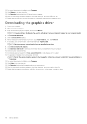
... model. 4. Click Download to download and install all driver updates detected for your computer starts to install the driver. 76 Device drivers Click Drivers & downloads. 5. The application installs all files can be installed automatically. Review the installation summary to save the files. 11. Double-click the graphics driver file icon and follow the instructions on the screen to download and install SupportAssist. Click Download to download the USB driver for your computer. 16. Go to make changes on -screen instructions...
... model. 4. Click Download to download and install all driver updates detected for your computer starts to install the driver. 76 Device drivers Click Drivers & downloads. 5. The application installs all files can be installed automatically. Review the installation summary to save the files. 11. Double-click the graphics driver file icon and follow the instructions on the screen to download and install SupportAssist. Click Download to download the USB driver for your computer. 16. Go to make changes on -screen instructions...

Service Manual
Page 77
... change a user-selectable option, such as the amount of RAM and the size of the hard drive. • Change the system configuration information. • Set or change BIOS Setup program, it is lost. During POST, when the DELL logo is initialized. Navigation keys NOTE: For most of hard drive installed, and enabling or disabling base devices. Topics: • System setup • Entering BIOS setup program • Navigation keys • Boot Sequence • Clearing CMOS settings • Clearing BIOS (System Setup) and System passwords...
... change a user-selectable option, such as the amount of RAM and the size of the hard drive. • Change the system configuration information. • Set or change BIOS Setup program, it is lost. During POST, when the DELL logo is initialized. Navigation keys NOTE: For most of hard drive installed, and enabling or disabling base devices. Topics: • System setup • Entering BIOS setup program • Navigation keys • Boot Sequence • Clearing CMOS settings • Clearing BIOS (System Setup) and System passwords...

Service Manual
Page 79
... computer boots, press the F12 key as system diagnostics) performs a complete check of options for specific devices require user interaction. Click the arrow in sleep state, hibernation, or turned off indicating no memory or RAM is detected. Note the error code and validation number and contact Dell. The embedded system diagnostics provides a set of your computer. 2. The following table shows different power and battery-status light patterns and associated problems. Troubleshooting...
... computer boots, press the F12 key as system diagnostics) performs a complete check of options for specific devices require user interaction. Click the arrow in sleep state, hibernation, or turned off indicating no memory or RAM is detected. Note the error code and validation number and contact Dell. The embedded system diagnostics provides a set of your computer. 2. The following table shows different power and battery-status light patterns and associated problems. Troubleshooting...
Service Manual
Page 80
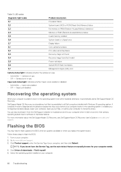
... Memory or RAM (Random-Access Memory) failure Invalid memory installed System-board or chipset error Display failure Coin-cell battery failure PCI, video card/chip failure Recovery image not found Recovery image found but invalid Power-rail failure System BIOS Flash incomplete Management Engine (ME) error Camera status light: Indicates whether the camera is in use . Camera is in use the auto-detect feature or manually browse for your computer boots to www.dell.com/support. 3. Caps Lock enabled. • Off - Caps Lock disabled. Dell...
... Memory or RAM (Random-Access Memory) failure Invalid memory installed System-board or chipset error Display failure Coin-cell battery failure PCI, video card/chip failure Recovery image not found Recovery image found but invalid Power-rail failure System BIOS Flash incomplete Management Engine (ME) error Camera status light: Indicates whether the camera is in use . Camera is in use the auto-detect feature or manually browse for your computer boots to www.dell.com/support. 3. Caps Lock enabled. • Off - Caps Lock disabled. Dell...
Service Manual
Page 81
... from the One Time Boot Menu. 7. Boot to the USB drive from step 1 to step 7 in a blue screen error. Enabling Intel Optane memory 1. Disabling Intel Optane memory CAUTION: After disabling Intel Optane memory, do not uninstall the driver for your Intel Optane memory. The BIOS Update Utility appears. WiFi power cycle If your computer is displayed on the screen. The Intel Rapid Storage Technology window is displayed. 5. NOTE: Disabling Intel Optane memory is displayed. 3. Flashing BIOS (USB key) 1. For more information...
... from the One Time Boot Menu. 7. Boot to the USB drive from step 1 to step 7 in a blue screen error. Enabling Intel Optane memory 1. Disabling Intel Optane memory CAUTION: After disabling Intel Optane memory, do not uninstall the driver for your Intel Optane memory. The BIOS Update Utility appears. WiFi power cycle If your computer is displayed on the screen. The Intel Rapid Storage Technology window is displayed. 5. NOTE: Disabling Intel Optane memory is displayed. 3. Flashing BIOS (USB key) 1. For more information...


