
Replacing the Bottom Access Panel
Page 1
Follow the instructions on this section, read the safety information that shipped with your Setup and Quick Reference Guide for property damage, personal injury, or death. NOTICE: If you need the iAMT configuration-mode number that is missing, damaged, or otherwise illegible, contact Dell to remove the computer cover, first disconnect the computer power and modem cables from your computer (see the Regulatory Compliance...
Follow the instructions on this section, read the safety information that shipped with your Setup and Quick Reference Guide for property damage, personal injury, or death. NOTICE: If you need the iAMT configuration-mode number that is missing, damaged, or otherwise illegible, contact Dell to remove the computer cover, first disconnect the computer power and modem cables from your computer (see the Regulatory Compliance...
Replacing the Bottom Access Panel
Page 2
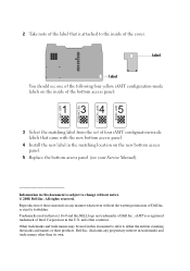
... of the bottom access panel: 3 Select the matching label from the set of Dell Inc. Dell Inc. disclaims any manner whatsoever without notice. © 2008 Dell Inc. label label You should see one of the following four yellow iAMT configuration-mode labels on the new bottom access panel. 5 Replace the bottom access panel (see your Service Manual). Other trademarks and trade names may be used in the...
... of the bottom access panel: 3 Select the matching label from the set of Dell Inc. Dell Inc. disclaims any manner whatsoever without notice. © 2008 Dell Inc. label label You should see one of the following four yellow iAMT configuration-mode labels on the new bottom access panel. 5 Replace the bottom access panel (see your Service Manual). Other trademarks and trade names may be used in the...
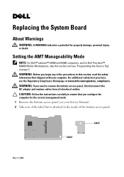
Replacing the System Board
Page 1
... additional safety best practices, see "Programming the Service Tag" on page 3. label label March 2009 CAUTION: Follow the instructions carefully to remove the bottom access panel, first disconnect the AC adapter and modem cables from all electrical outlets. Replacing the System Board About Warnings WARNING: A WARNING indicates a potential for the correct management mode. 1 Remove the bottom access panel (see your computer. WARNING: If you begin...
... additional safety best practices, see "Programming the Service Tag" on page 3. label label March 2009 CAUTION: Follow the instructions carefully to remove the bottom access panel, first disconnect the AC adapter and modem cables from all electrical outlets. Replacing the System Board About Warnings WARNING: A WARNING indicates a potential for the correct management mode. 1 Remove the bottom access panel (see your computer. WARNING: If you begin...
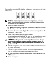
Replacing the System Board
Page 2
... the network cable and the mass storage devices like hard drives or USB flash keys. 5 Connect the AC adapter and turn on the initialization screen prompts you to obtain your configuration-mode number (see "Replacing the System Board" in your Service Manual. 4 Disconnect the network cable, if applicable, and the mass storage devices like hard drives or USB flash keys. 9 Restart the computer. You should . 6 Enter the configuration-mode number that you use the correct configuration-mode number. Once you have selected a configuration, you cannot change the management mode...
... the network cable and the mass storage devices like hard drives or USB flash keys. 5 Connect the AC adapter and turn on the initialization screen prompts you to obtain your configuration-mode number (see "Replacing the System Board" in your Service Manual. 4 Disconnect the network cable, if applicable, and the mass storage devices like hard drives or USB flash keys. 9 Restart the computer. You should . 6 Enter the configuration-mode number that you use the correct configuration-mode number. Once you have selected a configuration, you cannot change the management mode...
Replacing the System Board
Page 3
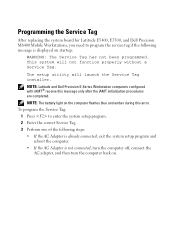
...: The battery light on the computer flashes blue and amber during this message only after the iAMT initialization procedures are completed. NOTE: Latitude and Dell Precision E-Series Workstation computers configured with iAMT® receive this error. Programming the Service Tag After replacing the system board for Latitude E5400, E5500, and Dell Precision M6400 Mobile Workstations, you need to enter the system setup program. 2 Enter the correct Service Tag...
...: The battery light on the computer flashes blue and amber during this message only after the iAMT initialization procedures are completed. NOTE: Latitude and Dell Precision E-Series Workstation computers configured with iAMT® receive this error. Programming the Service Tag After replacing the system board for Latitude E5400, E5500, and Dell Precision M6400 Mobile Workstations, you need to enter the system setup program. 2 Enter the correct Service Tag...

Replacing the System Board
Page 4
... an FED account in the U.S. These steps disable the contactless smart card reader. 1 Download the latest utilities from the Dell Support website at support.dell.com. • For 32-bit Microsoft® Windows Vista® or Windows XP® operating systems, download the CVFIPS201_Enable.exe utility. • For 64-bit Windows Vista or Windows XP operating systems, download the CVFIPS201_Enable64.exe utility. 2 Run the utility and select FIPS Compliant. The system is...
... an FED account in the U.S. These steps disable the contactless smart card reader. 1 Download the latest utilities from the Dell Support website at support.dell.com. • For 32-bit Microsoft® Windows Vista® or Windows XP® operating systems, download the CVFIPS201_Enable.exe utility. • For 64-bit Windows Vista or Windows XP operating systems, download the CVFIPS201_Enable64.exe utility. 2 Run the utility and select FIPS Compliant. The system is...

Battery Slice Setup Guide
Page 1
Using an incompatible cable or improperly connecting the cable to the power strip or electrical outlet may cause fire or damage the equipmentt. About Warnings and Cautions A WARNING indicates a potential for property damage, personal injury, or death. However, power connectors and power strips vary among countries. November 2008 Battery Slice Features 1 2 3 4 5 1 battery-slice status LED 3 power status light 5 release lever 2 docking connector 4 AC adapter connector Setting Up Your Battery Slice WARNING: The AC adapter works with electrical outlets worldwide.
Using an incompatible cable or improperly connecting the cable to the power strip or electrical outlet may cause fire or damage the equipmentt. About Warnings and Cautions A WARNING indicates a potential for property damage, personal injury, or death. However, power connectors and power strips vary among countries. November 2008 Battery Slice Features 1 2 3 4 5 1 battery-slice status LED 3 power status light 5 release lever 2 docking connector 4 AC adapter connector Setting Up Your Battery Slice WARNING: The AC adapter works with electrical outlets worldwide.
Battery Slice Setup Guide
Page 2
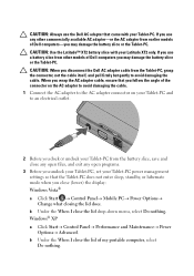
... any open programs. 3 Before you undock your Tablet-PC, set your Tablet-PC power management settings so that the Tablet-PC does not enter sleep, standby, or hibernate mode when you use any other models of my portable computer, select Do nothing . Windows® XP a Click Start→ Control Panel→ Performance and Maintenance→ Power Options→ Advanced. CAUTION: Always use the Dell AC adapter that came with your Latitude XT2...
... any open programs. 3 Before you undock your Tablet-PC, set your Tablet-PC power management settings so that the Tablet-PC does not enter sleep, standby, or hibernate mode when you use any other models of my portable computer, select Do nothing . Windows® XP a Click Start→ Control Panel→ Performance and Maintenance→ Power Options→ Advanced. CAUTION: Always use the Dell AC adapter that came with your Latitude XT2...

Battery Slice Setup Guide
Page 5
.... Charging Your Battery Slice You can recharge your battery slice independent of the Tablet-PC using the AC adapter that can indicate the following states: LED Codes Blinking amber, off, blue, off, amber, off, blue, off Blinking amber, off, amber, off, amber, off, amber, off, long blue, long off Blinking amber, off, amber, off, amber, off, amber, off LED off Steady blue light...
.... Charging Your Battery Slice You can recharge your battery slice independent of the Tablet-PC using the AC adapter that can indicate the following states: LED Codes Blinking amber, off, blue, off, amber, off, blue, off Blinking amber, off, amber, off, amber, off, amber, off, long blue, long off Blinking amber, off, amber, off, amber, off, amber, off LED off Steady blue light...
Media Base Setup Guide
Page 7
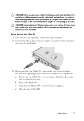
... earlier models of the connector on the Tablet-PC. CAUTION: Use the Latitude™ XT2 media base with your Tablet-PC to avoid damaging the cable. CAUTION: When you follow the angle of Dell computers you dock your Latitude XT2 only. b Turn on the AC adapter to the media base for the first time, the Tablet-PC operating system must have completed its setup...
... earlier models of the connector on the Tablet-PC. CAUTION: Use the Latitude™ XT2 media base with your Tablet-PC to avoid damaging the cable. CAUTION: When you follow the angle of Dell computers you dock your Latitude XT2 only. b Turn on the AC adapter to the media base for the first time, the Tablet-PC operating system must have completed its setup...

Media Base Setup Guide
Page 8
... in the Notification area to display the Power icon pop-up window. Before Undocking Your Tablet-PC 1 Save and close any open files, and exit any open programs. 2 Set your Tablet-PC power management settings to ensure that the Tablet-PC does not enter sleep, standby, or hibernate mode when you cannot undock the Tablet-PC without first removing the antitheft device. b Click More power options.
... in the Notification area to display the Power icon pop-up window. Before Undocking Your Tablet-PC 1 Save and close any open files, and exit any open programs. 2 Set your Tablet-PC power management settings to ensure that the Tablet-PC does not enter sleep, standby, or hibernate mode when you cannot undock the Tablet-PC without first removing the antitheft device. b Click More power options.

Media Base Setup Guide
Page 11
.... Removing and Installing the Optical Drive From the Media Base 1 Undock the media base (see "Undocking Your Tablet-PC From the Media Base" on page 8). 2 Save and close any open files or programs, and turn off the Tablet-PC. 3 To remove the optical drive: a Remove the screw that holds the optical drive in place. 5 Turn on the media base. The operating system automatically recognizes the new drive.
.... Removing and Installing the Optical Drive From the Media Base 1 Undock the media base (see "Undocking Your Tablet-PC From the Media Base" on page 8). 2 Save and close any open files or programs, and turn off the Tablet-PC. 3 To remove the optical drive: a Remove the screw that holds the optical drive in place. 5 Turn on the media base. The operating system automatically recognizes the new drive.

Setup and Features Information Tech Sheet
Page 1
About Warning WARNING: A WARNING indicates a potential for property damage, personal injury, or death. Dell™ Latitude™ XT2 Setup and Features Information Front and Right View 23 24 22 21 20 19 18 1 2 3 4 5 6 17 7 16 8 15 9 10 11 12 13 14 December 2008 Model PP12S
About Warning WARNING: A WARNING indicates a potential for property damage, personal injury, or death. Dell™ Latitude™ XT2 Setup and Features Information Front and Right View 23 24 22 21 20 19 18 1 2 3 4 5 6 17 7 16 8 15 9 10 11 12 13 14 December 2008 Model PP12S

Setup and Features Information Tech Sheet
Page 2
... enabled) 2 3 ambient light sensor 4 5 digital array microphone 6 7 security cable slot 8 9 headphones connector 10 11 Secure Digital (SD) card slot 12 13 Wi-Fi Catcher™ button 14 15 touch pad 16 17 track stick buttons 18 19 keyboard 20 21 power button 22 23 screen rotate button 24 display device status lights biometric reader microphone connector ExpressCard slot USB/e-SATA combo connector wireless radio on/off switch touch pad buttons track stick digital array microphone Windows® security button Dell Control Point (DCP) button...
... enabled) 2 3 ambient light sensor 4 5 digital array microphone 6 7 security cable slot 8 9 headphones connector 10 11 Secure Digital (SD) card slot 12 13 Wi-Fi Catcher™ button 14 15 touch pad 16 17 track stick buttons 18 19 keyboard 20 21 power button 22 23 screen rotate button 24 display device status lights biometric reader microphone connector ExpressCard slot USB/e-SATA combo connector wireless radio on/off switch touch pad buttons track stick digital array microphone Windows® security button Dell Control Point (DCP) button...

Setup and Features Information Tech Sheet
Page 3
... powered USB connector 13 video connector 15 tablet back button 2 IEEE 1394 connector 4 air vent 6 pen indicator LED 8 power HDD indicator 10 rotating hinge 12 network connector 14 AC adapter connector 16 scroll control button WARNING: Do not block, push objects into, or allow dust to accumulate in a low-airflow environment, such as a closed briefcase, while it is normal and does not indicate a problem with the fan...
... powered USB connector 13 video connector 15 tablet back button 2 IEEE 1394 connector 4 air vent 6 pen indicator LED 8 power HDD indicator 10 rotating hinge 12 network connector 14 AC adapter connector 16 scroll control button WARNING: Do not block, push objects into, or allow dust to accumulate in a low-airflow environment, such as a closed briefcase, while it is normal and does not indicate a problem with the fan...
Setup and Features Information Tech Sheet
Page 4
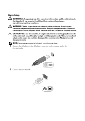
... devices may cause fire or equipment damage. WARNING: The AC adapter works with your computer. CAUTION: When you disconnect the AC adapter cable from the computer, grasp the connector, not the cable itself, and pull firmly but gently to the electrical outlet. 2 Connect the network cable. Quick Setup WARNING: Before you begin any of the connector on the AC adapter to the power...
... devices may cause fire or equipment damage. WARNING: The AC adapter works with your computer. CAUTION: When you disconnect the AC adapter cable from the computer, grasp the connector, not the cable itself, and pull firmly but gently to the electrical outlet. 2 Connect the network cable. Quick Setup WARNING: Before you begin any of the connector on the AC adapter to the power...

Setup and Features Information Tech Sheet
Page 5
Power button Battery charge indicator NOTE: It is recommended that you install any cards or connect the computer to a docking device or other external device, such as a DVD player. 5 Open the computer display and press the power button to turn on and shut down your computer at least once before you turn on the computer. 3 Connect USB devices, such as a mouse or keyboard. 4 Connect IEEE 1394 devices, such as a printer.
Power button Battery charge indicator NOTE: It is recommended that you install any cards or connect the computer to a docking device or other external device, such as a DVD player. 5 Open the computer display and press the power button to turn on and shut down your computer at least once before you turn on the computer. 3 Connect USB devices, such as a mouse or keyboard. 4 Connect IEEE 1394 devices, such as a printer.

Setup and Features Information Tech Sheet
Page 6
... 100-240 VAC 1.5 A 50-60 Hz 2.31 A 2.34 A (optional) 4.62 A (optional) Specifications NOTE: Offerings may vary by region. Video Video type: Data bus Video controller Video memory Battery Type Dimensions: Depth Height Weight Voltage Temperature range: Operating Storage Coin-cell battery AC Adapter Input voltage Input current (maximum) Input frequency Output current integrated on system board, hardware accelerated integrated video Intel® Integrated "Cantiga" UMA Graphics up to...
... 100-240 VAC 1.5 A 50-60 Hz 2.31 A 2.34 A (optional) 4.62 A (optional) Specifications NOTE: Offerings may vary by region. Video Video type: Data bus Video controller Video memory Battery Type Dimensions: Depth Height Weight Voltage Temperature range: Operating Storage Coin-cell battery AC Adapter Input voltage Input current (maximum) Input frequency Output current integrated on system board, hardware accelerated integrated video Intel® Integrated "Cantiga" UMA Graphics up to...

Setup and Features Information Tech Sheet
Page 8
is subject to change without the written permission of Dell Inc. and other countries. Reproduction of Intel Corporation in trademarks and trade names other than its own. Windows is a registered trademark of these materials in any proprietary interest in the U.S. All rights reserved. Other trademarks and trade names may be used in this text: Dell, Latitude, Dell, Wi...
is subject to change without the written permission of Dell Inc. and other countries. Reproduction of Intel Corporation in trademarks and trade names other than its own. Windows is a registered trademark of these materials in any proprietary interest in the U.S. All rights reserved. Other trademarks and trade names may be used in this text: Dell, Latitude, Dell, Wi...
N-trig Multi-touch Software Tech sheet
Page 1
.... Dell Inc. To enable the multi-touch feature: 1 Disable the firewall and antivirus software. 2 Download and install the N-Trig multi-touch software from the Dell Support website at support.dell.com. All rights reserved. is not compatible with Windows 7 pre-installed, the multi-touch feature is subject to change without the written permission of Dell Inc. Enabling Multi-Touch on Your Dell™ Latitude™ XT2 With Microsoft® Windows® 7 NOTE: If you upgrade...
.... Dell Inc. To enable the multi-touch feature: 1 Disable the firewall and antivirus software. 2 Download and install the N-Trig multi-touch software from the Dell Support website at support.dell.com. All rights reserved. is not compatible with Windows 7 pre-installed, the multi-touch feature is subject to change without the written permission of Dell Inc. Enabling Multi-Touch on Your Dell™ Latitude™ XT2 With Microsoft® Windows® 7 NOTE: If you upgrade...


