
Tower Owners Manual
Page 3
......23 Expansion card...24 Removing PCIe expansion card...24 Installing PCIe expansion card...25 WLAN card...27 Removing WLAN card...27 Installing WLAN card...30 Power supply unit...32 Contents 3
......23 Expansion card...24 Removing PCIe expansion card...24 Installing PCIe expansion card...25 WLAN card...27 Removing WLAN card...27 Installing WLAN card...30 Power supply unit...32 Contents 3

Tower Owners Manual
Page 4
Removing power supply unit or PSU...32 Installing power supply unit or PSU...34 VGA daughter board...35 Removing VGA daughter board...35 Installing VGA daughter board...36 Intrusion switch...39 Removing intrusion switch...39 Installing intrusion switch...40 Power switch...41 Removing power switch...41 Installing power switch...42 Speaker...42 Removing speaker...42 Installing speaker...44...
Removing power supply unit or PSU...32 Installing power supply unit or PSU...34 VGA daughter board...35 Removing VGA daughter board...35 Installing VGA daughter board...36 Intrusion switch...39 Removing intrusion switch...39 Installing intrusion switch...40 Power switch...41 Removing power switch...41 Installing power switch...42 Speaker...42 Removing speaker...42 Installing speaker...44...

Tower Owners Manual
Page 5
... ePSA Diagnostic 3.0 87 Running the ePSA Diagnostics...87 Diagnostic error messages...87 System error messages...90 Power Supply Unit (PSU) Built-in Windows ...76 Updating your system BIOS using a USB flash drive 76 Enabling smart power on...77 6 Software...78 Supported operating systems...78 Downloading drivers...78 Downloading the chipset driver...78 ......80 Downloading the Wi-Fi driver...80 Realtek HD audio drivers...81 Downloading the audio driver...81 7 Troubleshooting your computer...82 Diagnostic and Power LED codes...82 Power LED issue...86 Dell Enhanced Pre-Boot System Assessment -
... ePSA Diagnostic 3.0 87 Running the ePSA Diagnostics...87 Diagnostic error messages...87 System error messages...90 Power Supply Unit (PSU) Built-in Windows ...76 Updating your system BIOS using a USB flash drive 76 Enabling smart power on...77 6 Software...78 Supported operating systems...78 Downloading drivers...78 Downloading the chipset driver...78 ......80 Downloading the Wi-Fi driver...80 Realtek HD audio drivers...81 Downloading the audio driver...81 7 Troubleshooting your computer...82 Diagnostic and Power LED codes...82 Power LED issue...86 Dell Enhanced Pre-Boot System Assessment -

Tower Owners Manual
Page 6
Power supply specifications...94 Physical dimension specifications...95 System board layout...95 Controls and lights specifications...96 Environmental specifications...96 9 Contacting Dell...98 6 Contents
Power supply specifications...94 Physical dimension specifications...95 System board layout...95 Controls and lights specifications...96 Environmental specifications...96 9 Contacting Dell...98 6 Contents

Tower Owners Manual
Page 32
b Unroute the PSU cable from the retention clip [3]. f Remove the screws that secure the PSU to the computer [4]. 32 Disassembly and reassembly e Unroute the PSU cables from the release clip [2]. c Disconnect the PSU cable from the connector on the system board [1]. Power supply unit Removing power supply unit or PSU 1 Follow the procedure in Before working inside your computer. 2 Remove the: a cover b bezel 3 Open the front panel door. 4 To release the PSU: a Disconnect the PSU cable from the connector on the system board [1]. d Pull the release clip [2].
b Unroute the PSU cable from the retention clip [3]. f Remove the screws that secure the PSU to the computer [4]. 32 Disassembly and reassembly e Unroute the PSU cables from the release clip [2]. c Disconnect the PSU cable from the connector on the system board [1]. Power supply unit Removing power supply unit or PSU 1 Follow the procedure in Before working inside your computer. 2 Remove the: a cover b bezel 3 Open the front panel door. 4 To release the PSU: a Disconnect the PSU cable from the connector on the system board [1]. d Pull the release clip [2].

Tower Owners Manual
Page 34
Installing power supply unit or PSU 1 Insert the PSU into the PSU slot and slide it towards the back of the computer until it clicks into place. 2 Tighten the screws to secure the PSU to the computer. 3 Route the PSU cables through the retention clips and secure one of the cables with the release clips. 4 Connect the PSU cables to the connectors on the system board. 5 Close the front panel door. 6 Install the: a bezel b cover 7 Follow the procedure in After working inside your computer. 34 Disassembly and reassembly
Installing power supply unit or PSU 1 Insert the PSU into the PSU slot and slide it towards the back of the computer until it clicks into place. 2 Tighten the screws to secure the PSU to the computer. 3 Route the PSU cables through the retention clips and secure one of the cables with the release clips. 4 Connect the PSU cables to the connectors on the system board. 5 Close the front panel door. 6 Install the: a bezel b cover 7 Follow the procedure in After working inside your computer. 34 Disassembly and reassembly

Tower Owners Manual
Page 74
...When this works only when the operating system supports Simple Boot Flag). This option is disabled by default. This allows the operating system to power up and immediately boot to automatically turn off state when triggered by special LAN signals when it receives a wake-up the boot process ... - Sets time to PXE. • WLAN Only - This feature only works when the computer is connected to be powered on by a special LAN signal. Allows the system to AC power supply. • Disabled - The system does not skip any steps in either the S4 or S5 state, that will cause...
...When this works only when the operating system supports Simple Boot Flag). This option is disabled by default. This allows the operating system to power up and immediately boot to automatically turn off state when triggered by special LAN signals when it receives a wake-up the boot process ... - Sets time to PXE. • WLAN Only - This feature only works when the computer is connected to be powered on by a special LAN signal. Allows the system to AC power supply. • Disabled - The system does not skip any steps in either the S4 or S5 state, that will cause...

Tower Owners Manual
Page 83
...Problem Description Bad Motherboard Suggested Resolution Replace the motherboard 2 blinks > short pause > 2 blinks > long pause > repeats Bad Motherboard, Power Supply or Power Supply cabling If customer can assist to troubleshoot, narrow down the issue by long pause then repeats. If problem persists, replace the motherboard ... blinks up to troubleshoot, narrow down the issue with PSU BIST Test, reseat cable. If nothing works, replace the motherboard, power supply or cabling 2 blinks > short pause > 3 blinks > long pause > repeats Bad Motherboard, Memory or Processor If customer ...
...Problem Description Bad Motherboard Suggested Resolution Replace the motherboard 2 blinks > short pause > 2 blinks > long pause > repeats Bad Motherboard, Power Supply or Power Supply cabling If customer can assist to troubleshoot, narrow down the issue by long pause then repeats. If problem persists, replace the motherboard ... blinks up to troubleshoot, narrow down the issue with PSU BIST Test, reseat cable. If nothing works, replace the motherboard, power supply or cabling 2 blinks > short pause > 3 blinks > long pause > repeats Bad Motherboard, Memory or Processor If customer ...
Tower Owners Manual
Page 91
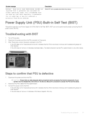
Dell recommends that you take adequate safety precautions before accessing the internal components of range may or may not indicate a potential hard drive problem Description S.M.A.R.T error, possible hard disk drive failure. BIST can be performed by simply connecting the AC power cord to confirm that the..., and wait for 15 seconds. 3 After 15 seconds, connect the power cord back to access the PSU and its normal operating range. Power Supply Unit (PSU) Built-in Self Test (BIST) This system supports a new Power Supply Unit (PSU) Built-in the Service Manual for procedure to the PSU...
Dell recommends that you take adequate safety precautions before accessing the internal components of range may or may not indicate a potential hard drive problem Description S.M.A.R.T error, possible hard disk drive failure. BIST can be performed by simply connecting the AC power cord to confirm that the..., and wait for 15 seconds. 3 After 15 seconds, connect the power cord back to access the PSU and its normal operating range. Power Supply Unit (PSU) Built-in Self Test (BIST) This system supports a new Power Supply Unit (PSU) Built-in the Service Manual for procedure to the PSU...
Tower Owners Manual
Page 92
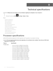
... • Audio specifications • Communication specifications • Storage specifications • Ports and connectors specifications • Power supply specifications • Physical dimension specifications • System board layout • Controls and lights specifications • Environmental specifications Processor specifications OptiPlex 3050 systems are shipped with Intel 6th generation and 7th generation core processor technology. Feature Specification Processor...
... • Audio specifications • Communication specifications • Storage specifications • Ports and connectors specifications • Power supply specifications • Physical dimension specifications • System board layout • Controls and lights specifications • Environmental specifications Processor specifications OptiPlex 3050 systems are shipped with Intel 6th generation and 7th generation core processor technology. Feature Specification Processor...

Tower Owners Manual
Page 94
... port VGA port PS/2 Serial/Parallel Specification One Two Two Two Two One One One One One One (optional) Two (optional) One (optional) Power supply specifications Feature Type Frequency Voltage Input current Coin cell battery Specification 240 W 47 Hz - 63 Hz 90 VAC - 264 VAC 4 A / 2 A 3 V CR2032 lithium coin cell 94 ...
... port VGA port PS/2 Serial/Parallel Specification One Two Two Two Two One One One One One One (optional) Two (optional) One (optional) Power supply specifications Feature Type Frequency Voltage Input current Coin cell battery Specification 240 W 47 Hz - 63 Hz 90 VAC - 264 VAC 4 A / 2 A 3 V CR2032 lithium coin cell 94 ...

Tower Owners Manual
Page 96
... the network and the computer. Network activity light on state; Power supply diagnostic light Green light - 13 Memory module connectors 15 Power switch connector 17 SATA 1 connector 19 Speaker connector 21 HDD and ODD power connector 23 CMOS_CLR/Password/Service_Mode Jumper 14 Card reader connector 16 ...not detecting a physical connection to the power connector (at the back of the computer. The power cable must be connected to the network. a good 10 Mbps or 100 Mbps connection exists between the network and the computer. The power supply is turned on Green - blinking white...
... the network and the computer. Network activity light on state; Power supply diagnostic light Green light - 13 Memory module connectors 15 Power switch connector 17 SATA 1 connector 19 Speaker connector 21 HDD and ODD power connector 23 CMOS_CLR/Password/Service_Mode Jumper 14 Card reader connector 16 ...not detecting a physical connection to the power connector (at the back of the computer. The power cable must be connected to the network. a good 10 Mbps or 100 Mbps connection exists between the network and the computer. The power supply is turned on Green - blinking white...

Small Form Factor Owners Manual
Page 4
... card reader...23 Removing the SD card reader...23 Installing the SD card reader...23 Power supply unit...24 Removing power supply unit or PSU...24 Installing the power supply unit or PSU...26 Power switch...26 Removing power switch...26 Installing the power switch...27 System board...27 Removing system board...27 Installing the system board...31 System...
... card reader...23 Removing the SD card reader...23 Installing the SD card reader...23 Power supply unit...24 Removing power supply unit or PSU...24 Installing the power supply unit or PSU...26 Power switch...26 Removing power switch...26 Installing the power switch...27 System board...27 Removing system board...27 Installing the system board...31 System...

Small Form Factor Owners Manual
Page 5
... specifications...61 Processor specifications...61 Memory specifications...62 Video specifications...62 Audio specifications...62 Communication specifications...62 Storage specifications...63 Ports and connectors specifications...63 Power supply specifications...63 Physical dimension specifications...64 Controls and lights specifications...64 Environmental specifications...64 9 Contacting...
... specifications...61 Processor specifications...61 Memory specifications...62 Video specifications...62 Audio specifications...62 Communication specifications...62 Storage specifications...63 Ports and connectors specifications...63 Power supply specifications...63 Physical dimension specifications...64 Controls and lights specifications...64 Environmental specifications...64 9 Contacting...

Small Form Factor Owners Manual
Page 23
... Before working inside your computer. 2 Remove the: a cover b bezel c hard drive and optical drive module d M.2 PCIe SSD 3 To remove the SD card reader: a Release the power supply unit cables from the retention clips on the chassis. 2 Tighten the screws that secure the SD card reader and lift it away from the computer [2] [3].
... Before working inside your computer. 2 Remove the: a cover b bezel c hard drive and optical drive module d M.2 PCIe SSD 3 To remove the SD card reader: a Release the power supply unit cables from the retention clips on the chassis. 2 Tighten the screws that secure the SD card reader and lift it away from the computer [2] [3].

Small Form Factor Owners Manual
Page 24
Power supply unit Removing power supply unit or PSU 1 Follow the procedure in After working inside your computer. 2 Remove the: a cover b bezel c hard drive and optical drive module 3 To release the PSU: a Disconnect the power cable from the system board [1] [2]. c Remove the screws that secure the PSU to the computer [4]. 24 Removing and installing components b Unroute...
Power supply unit Removing power supply unit or PSU 1 Follow the procedure in After working inside your computer. 2 Remove the: a cover b bezel c hard drive and optical drive module 3 To release the PSU: a Disconnect the power cable from the system board [1] [2]. c Remove the screws that secure the PSU to the computer [4]. 24 Removing and installing components b Unroute...

Small Form Factor Owners Manual
Page 26
... After working inside your computer. 2 Remove the: a cover b bezel c hard drive and optical drive module 26 Removing and installing components Installing the power supply unit or PSU 1 Insert the PSU in the chassis and slide it toward the back of the computer to secure it. 2 Tighten the screws to... secure the PSU to the back of the computer. 3 Route the PSU cables through the retention clips. 4 Connect the power cables to the system board. 5 Install the: a hard drive and optical drive module b bezel c cover 6 Follow the procedure in Before working inside your...
... After working inside your computer. 2 Remove the: a cover b bezel c hard drive and optical drive module 26 Removing and installing components Installing the power supply unit or PSU 1 Insert the PSU in the chassis and slide it toward the back of the computer to secure it. 2 Tighten the screws to... secure the PSU to the back of the computer. 3 Route the PSU cables through the retention clips. 4 Connect the power cables to the system board. 5 Install the: a hard drive and optical drive module b bezel c cover 6 Follow the procedure in Before working inside your...

Small Form Factor Owners Manual
Page 50
... wireless LAN. • LAN or WLAN - This option is enabled by bypassing some compatibility steps: • Minimal - Allows the system to power on by special LAN or wireless LAN signals. • LAN Only - This option is disabled by default. Allows you to enable or disable... process. • Auto - Allows you to control this setting (this option is selected by default This option allows the computer to AC power supply. • Disabled - This allows the operating system to determine the speed of Intel Ready Mode Technology. This option is enabled, the system...
... wireless LAN. • LAN or WLAN - This option is enabled by bypassing some compatibility steps: • Minimal - Allows the system to power on by special LAN or wireless LAN signals. • LAN Only - This option is disabled by default. Allows you to enable or disable... process. • Auto - Allows you to control this setting (this option is selected by default This option allows the computer to AC power supply. • Disabled - This allows the operating system to determine the speed of Intel Ready Mode Technology. This option is enabled, the system...

Small Form Factor Owners Manual
Page 61
... specifications • Memory specifications • Video specifications • Audio specifications • Communication specifications • Storage specifications • Ports and connectors specifications • Power supply specifications • Physical dimension specifications • Controls and lights specifications • Environmental specifications Processor specifications OptiPlex 3050 systems are shipped with Intel 6th generation and 7th generation core processor technology.
... specifications • Memory specifications • Video specifications • Audio specifications • Communication specifications • Storage specifications • Ports and connectors specifications • Power supply specifications • Physical dimension specifications • Controls and lights specifications • Environmental specifications Processor specifications OptiPlex 3050 systems are shipped with Intel 6th generation and 7th generation core processor technology.

Small Form Factor Owners Manual
Page 63
... port PS/2 Parallel VGA port Specification One Two Two Two Two One (optional) One One One One One Two (optional) One (optional) One (optional) Power supply specifications Feature Type Frequency Voltage Input current Coin cell battery Specification 180 W 47 Hz - 63 Hz 90 VAC - 264 VAC 3 A / 1.5 A 3 V CR2032 lithium coin cell Technical ...
... port PS/2 Parallel VGA port Specification One Two Two Two Two One (optional) One One One One One Two (optional) One (optional) One (optional) Power supply specifications Feature Type Frequency Voltage Input current Coin cell battery Specification 180 W 47 Hz - 63 Hz 90 VAC - 264 VAC 3 A / 1.5 A 3 V CR2032 lithium coin cell Technical ...


