
Service Manual
Page 3
... Power supply specifications...9 Power adapter...9 Video specifications...10 Audio specifications...10 Memory ...10 Display specifications...11 Keyboard specifications...12 Battery...12 Storage specifications...13 USB Type-C...13 USB features...14 3 Major components of your system 17 4 Disassembly and reassembly...19 Disassembly and reassembly...19 Base cover...19 Battery...20 PCIe Solid State Drive (SSD)...21 Hard drive...23 Speaker...24 WLAN card...25 Memory modules...26 System fan...27 Heat sink assembly...30 Power connector port...31 System board...32 Audio board...34 Coin-cell battery...
... Power supply specifications...9 Power adapter...9 Video specifications...10 Audio specifications...10 Memory ...10 Display specifications...11 Keyboard specifications...12 Battery...12 Storage specifications...13 USB Type-C...13 USB features...14 3 Major components of your system 17 4 Disassembly and reassembly...19 Disassembly and reassembly...19 Base cover...19 Battery...20 PCIe Solid State Drive (SSD)...21 Hard drive...23 Speaker...24 WLAN card...25 Memory modules...26 System fan...27 Heat sink assembly...30 Power connector port...31 System board...32 Audio board...34 Coin-cell battery...
Service Manual
Page 5
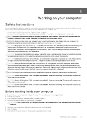
... 1. Hold a card by its pins. if you are correctly oriented and aligned. The system will not power on if the side cover is removed. The system will not power on if the side cover is removed. The system will shut down if side covers are removed while the system is running. Before working inside the computer, replace all network cables from their electrical outlets. 6. Turn off your...
... 1. Hold a card by its pins. if you are correctly oriented and aligned. The system will not power on if the side cover is removed. The system will not power on if the side cover is removed. The system will shut down if side covers are removed while the system is running. Before working inside the computer, replace all network cables from their electrical outlets. 6. Turn off your...
Service Manual
Page 6
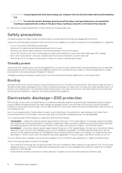
... essentially powered while turned off the system and all attached peripherals. • Disconnect the system and all attached peripherals from AC power. • Disconnect all network cables, telephone, and telecommunications lines from the system. • Use an ESD field service kit when working inside any tabletnotebookdesktop to avoid electrostatic discharge (ESD) damage. • After removing any disassembly instructions. An example of catastrophic failure...
... essentially powered while turned off the system and all attached peripherals. • Disconnect the system and all attached peripherals from AC power. • Disconnect all network cables, telephone, and telecommunications lines from the system. • Use an ESD field service kit when working inside any tabletnotebookdesktop to avoid electrostatic discharge (ESD) damage. • After removing any disassembly instructions. An example of catastrophic failure...

Service Manual
Page 7
... directly connected between your skin, the ESD mat, and the hardware is recommended to any hardware components • ESD Packaging - Never use the traditional wired ESD grounding wrist strap and protective anti-static mat at an ESD-protected work area that the internal wires of an ESD field service kit are typically installed in . A green LED is lit if the test is...
... directly connected between your skin, the ESD mat, and the hardware is recommended to any hardware components • ESD Packaging - Never use the traditional wired ESD grounding wrist strap and protective anti-static mat at an ESD-protected work area that the internal wires of an ESD field service kit are typically installed in . A green LED is lit if the test is...
Service Manual
Page 8
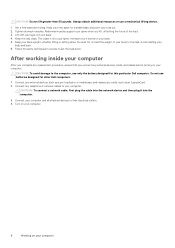
.... 4. CAUTION: To connect a network cable, first plug the cable into the network device and then plug it exerts on your computer. Connect any replacement procedure, ensure that you lift, offsetting the force of your body and back. 6. Get a firm balanced footing. Abdominal muscles support your spine when you connect any cards, such as a port replicator or media base, and replace any external devices, cards, and cables before turning on your computer...
.... 4. CAUTION: To connect a network cable, first plug the cable into the network device and then plug it exerts on your computer. Connect any replacement procedure, ensure that you lift, offsetting the force of your body and back. 6. Get a firm balanced footing. Abdominal muscles support your spine when you connect any cards, such as a port replicator or media base, and replace any external devices, cards, and cables before turning on your computer...

Service Manual
Page 10
... External display support HDMI 2.0 HDMI 2.0 HDMI 2.0 10 Technology and components Video Controller Type Integrated Intel UHD 630 Nvidia Quadro T1000 w/4GB GDDR5 Nvidia Quadro T2000 w/4GB GDDR5 GFX Discrete Discrete CPU Dependency Graphics memory Capacity type Intel HD GFX Integrated Shared system memory Intel Xeon E-2276M GDDR5 4 GB Intel Xeon E-2276M GDDR5 4 GB Audio specifications Table 4. Audio specifications Features Controller Type Interface Specification Waves MaxxAudio Pro Integrated • High-quality speakers • Dual...
... External display support HDMI 2.0 HDMI 2.0 HDMI 2.0 10 Technology and components Video Controller Type Integrated Intel UHD 630 Nvidia Quadro T1000 w/4GB GDDR5 Nvidia Quadro T2000 w/4GB GDDR5 GFX Discrete Discrete CPU Dependency Graphics memory Capacity type Intel HD GFX Integrated Shared system memory Intel Xeon E-2276M GDDR5 4 GB Intel Xeon E-2276M GDDR5 4 GB Audio specifications Table 4. Audio specifications Features Controller Type Interface Specification Waves MaxxAudio Pro Integrated • High-quality speakers • Dual...

Service Manual
Page 14
... USB connection. The USB 3.0/USB 3.1 Gen 1 finally has the answer to better accommodate power-hungry devices • New power management features • Full-duplex data transfers and support for new transfer types • Backward USB 2.0 compatibility • New connectors and cable The topics below . USB features Universal Serial Bus, or USB, was introduced in the PC world with everything charging via the one of all those portable battery packs you used...
... USB connection. The USB 3.0/USB 3.1 Gen 1 finally has the answer to better accommodate power-hungry devices • New power management features • Full-duplex data transfers and support for new transfer types • Backward USB 2.0 compatibility • New connectors and cable The topics below . USB features Universal Serial Bus, or USB, was introduced in the PC world with everything charging via the one of all those portable battery packs you used...

Service Manual
Page 15
...USB 3.0/USB 3.1 Gen 1 adds four more for two pairs of differential signals (receive and transmit) for a combined total of the available SuperSpeed USB 3.0/USB 3.1 Gen 1 products: • External Desktop USB 3.0/USB 3.1 Gen 1 Hard Drives • Portable USB 3.0/USB 3.1 Gen 1 Hard Drives • USB 3.0/USB 3.1 Gen 1 Drive Docks & Adapters • USB 3.0/USB 3.1 Gen 1 Flash Drives & Readers • USB 3.0/USB 3.1 Gen 1 Solid-state Drives • USB 3.0/USB 3.1 Gen 1 RAIDs • Optical Media Drives • Multimedia Devices • Networking • USB 3.0/USB 3.1 Gen 1 Adapter Cards...
...USB 3.0/USB 3.1 Gen 1 adds four more for two pairs of differential signals (receive and transmit) for a combined total of the available SuperSpeed USB 3.0/USB 3.1 Gen 1 products: • External Desktop USB 3.0/USB 3.1 Gen 1 Hard Drives • Portable USB 3.0/USB 3.1 Gen 1 Hard Drives • USB 3.0/USB 3.1 Gen 1 Drive Docks & Adapters • USB 3.0/USB 3.1 Gen 1 Flash Drives & Readers • USB 3.0/USB 3.1 Gen 1 Solid-state Drives • USB 3.0/USB 3.1 Gen 1 RAIDs • Optical Media Drives • Multimedia Devices • Networking • USB 3.0/USB 3.1 Gen 1 Adapter Cards...

Service Manual
Page 24
... After Working Inside Your Computer. battery 3. b. battery b. Remove the M2x2 (4) screws that secure the hard-drive cage to the palm-rest assembly. 7. Lift the speakers, along with the screw holes on the hard-drive cage with the speaker cable, off the computer [3]. 24 Disassembly and reassembly Connect the hard-drive interposer to the computer [2]. Replace the M2x4 (4) screws that secure the speakers to the hard-drive assembly. 3. Install the: a. base cover 8. Installing the Hard Drive -optional...
... After Working Inside Your Computer. battery 3. b. battery b. Remove the M2x2 (4) screws that secure the hard-drive cage to the palm-rest assembly. 7. Lift the speakers, along with the screw holes on the hard-drive cage with the speaker cable, off the computer [3]. 24 Disassembly and reassembly Connect the hard-drive interposer to the computer [2]. Replace the M2x4 (4) screws that secure the speakers to the hard-drive assembly. 3. Install the: a. base cover 8. Installing the Hard Drive -optional...

Service Manual
Page 32
... [2]. Battery b. System board Removing the System Board 1. base cover b. keyboard h. memory modules NOTE: Your computer's Service Tag is located under the system badge flap. Lift the latch and disconnect the touchpad cable [1]. Route the power-adapter port cable through its routing guides on the palm-rest assembly. 2. Base cover 6. heatsink assembly e. hard drive (optional) g. SSD i. Lift the latch and disconnect the keyboard controller board cable [2]. 32 Disassembly and reassembly b. Installing the DC-in After Working Inside Your...
... [2]. Battery b. System board Removing the System Board 1. base cover b. keyboard h. memory modules NOTE: Your computer's Service Tag is located under the system badge flap. Lift the latch and disconnect the touchpad cable [1]. Route the power-adapter port cable through its routing guides on the palm-rest assembly. 2. Base cover 6. heatsink assembly e. hard drive (optional) g. SSD i. Lift the latch and disconnect the keyboard controller board cable [2]. 32 Disassembly and reassembly b. Installing the DC-in After Working Inside Your...

Service Manual
Page 34
... board to the system board. 5. Install the: a. Memory b. SSD c. Hard drive(optional) g. Base cover 7. Follow the procedures in After Working Inside Your Computer. Remove the: a. Align the display-cable bracket with the screw hole on the computer. 2. Fans f. Follow the procedures in Before Working Inside Your Computer. 2. Connect the display cable to the palm-rest assembly. 3. Keyboard d. base cover 34 Disassembly and reassembly Connect the power-adapter port cable, speaker cable, keyboard-control board cable, touchpad cable, and touch-screen cable...
... board to the system board. 5. Install the: a. Memory b. SSD c. Hard drive(optional) g. Base cover 7. Follow the procedures in After Working Inside Your Computer. Remove the: a. Align the display-cable bracket with the screw hole on the computer. 2. Fans f. Follow the procedures in Before Working Inside Your Computer. 2. Connect the display cable to the palm-rest assembly. 3. Keyboard d. base cover 34 Disassembly and reassembly Connect the power-adapter port cable, speaker cable, keyboard-control board cable, touchpad cable, and touch-screen cable...

Service Manual
Page 36
... battery cable from the system board [1]. Replace the coin-cell battery in its slot in Before Working Inside Your Computer. Install the: 36 Disassembly and reassembly Turn the system board over . 4. Lift up the coin-cell battery [2]. Installing the Coin-Cell Battery 1. base cover b. hard drive e. Follow the procedures in the computer. 2. system board 3. Turn the system board over . memory modules h. b. Coin-cell battery Removing the Coin-Cell Battery 1. WLAN card d. CAUTION: Removing the coin-cell battery re-sets...
... battery cable from the system board [1]. Replace the coin-cell battery in its slot in Before Working Inside Your Computer. Install the: 36 Disassembly and reassembly Turn the system board over . 4. Lift up the coin-cell battery [2]. Installing the Coin-Cell Battery 1. base cover b. hard drive e. Follow the procedures in the computer. 2. system board 3. Turn the system board over . memory modules h. b. Coin-cell battery Removing the Coin-Cell Battery 1. WLAN card d. CAUTION: Removing the coin-cell battery re-sets...

Service Manual
Page 47
... assembly on the palm rest assembly to the palm rest assembly. 3. display assembly e. WLAN card i. hard drive(optional) j. Fingerprint reader function without light indicator Installing the Palm rest Assembly 1. Press down on the display assembly. 2. speakers h. Follow the procedures in After Working Inside Your Computer Disassembly and reassembly 47 Tighten the screws to secure the display hinges to close the display. 4. keyboard b. battery l. fans f. base cover 5. memory modules k. heatsink assembly g. power connector port d.
... assembly on the palm rest assembly to the palm rest assembly. 3. display assembly e. WLAN card i. hard drive(optional) j. Fingerprint reader function without light indicator Installing the Palm rest Assembly 1. Press down on the display assembly. 2. speakers h. Follow the procedures in After Working Inside Your Computer Disassembly and reassembly 47 Tighten the screws to secure the display hinges to close the display. 4. keyboard b. battery l. fans f. base cover 5. memory modules k. heatsink assembly g. power connector port d.

Setup and Specifications guide
Page 10
... 5.0 10 Engineering specifications BIOS defaults(continued) Video Performance Virtualization Support Security SupportAssist System Resolution Audio Keyboard Illumination Miscellaneous Devices LCD Brightness Multiple Core Support: Intel SpeedStep™: C States Control: Intel TurboBoost Virtualization VT for Direct I/O: Trusted Execution Password Password Configuration Password Bypass Password Change Non-Admin Setup Changes UEFI Capsule Firmware Updates TPM 2.0 Security Computrace CPU XD Support OROM Keyboard Access Admin Setup Lockout Master Password Lockout Auto OS Recovery Threshold...
... 5.0 10 Engineering specifications BIOS defaults(continued) Video Performance Virtualization Support Security SupportAssist System Resolution Audio Keyboard Illumination Miscellaneous Devices LCD Brightness Multiple Core Support: Intel SpeedStep™: C States Control: Intel TurboBoost Virtualization VT for Direct I/O: Trusted Execution Password Password Configuration Password Bypass Password Change Non-Admin Setup Changes UEFI Capsule Firmware Updates TPM 2.0 Security Computrace CPU XD Support OROM Keyboard Access Admin Setup Lockout Master Password Lockout Auto OS Recovery Threshold...

Setup and Specifications guide
Page 18
... technology. Dell Precision 5530 (Default Setting) Displays the service tag. Allows you to set the date and time. Displays the CPU speed. Displays the type and size of the memory. None (Default Setting) Displays the CPU type. Displays the speed of the HDD. Enabled (Default Setting) This option enables or disables additional processor sleep states. Displays the CPU ID. Displays the type of the system memory. None (Default Setting) Displays the size of the AC adapter. System Setup Options NOTE: Depending on your computer and its installed devices, the items listed in...
... technology. Dell Precision 5530 (Default Setting) Displays the service tag. Allows you to set the date and time. Displays the CPU speed. Displays the type and size of the memory. None (Default Setting) Displays the CPU type. Displays the speed of the HDD. Enabled (Default Setting) This option enables or disables additional processor sleep states. Displays the CPU ID. Displays the type of the system memory. None (Default Setting) Displays the size of the AC adapter. System Setup Options NOTE: Depending on your computer and its installed devices, the items listed in...

Setup and Specifications guide
Page 19
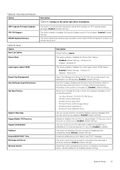
...Disabled (Default Setting) Allows you to turn on automatically. Disabled (Default Setting) Maximizes battery health while still supporting heavy use during the work day. Allows you to wake the system from Standby. Disabled (Default Setting) System Setup 19 Disabled (Default Setting) Lets you to enable USB devices to configure the integrated USB controller. Disabled (Default Setting) Minimizes AC power usage at times of the keyboard illumination feature. Enabled (Default Setting) This option allows you to block entering to power-on board devices. Enabled (Default...
...Disabled (Default Setting) Allows you to turn on automatically. Disabled (Default Setting) Maximizes battery health while still supporting heavy use during the work day. Allows you to wake the system from Standby. Disabled (Default Setting) System Setup 19 Disabled (Default Setting) Lets you to enable USB devices to configure the integrated USB controller. Disabled (Default Setting) Minimizes AC power usage at times of the keyboard illumination feature. Enabled (Default Setting) This option allows you to block entering to power-on board devices. Enabled (Default...
Setup and Specifications guide
Page 20
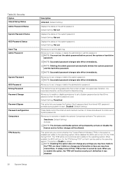
... to the operating system. This field enforces strong passwords that it delete or change or delete the administrator password. Default Setting: Permitted This option lets you to set , change any information or keys you re-enable this option does not change or delete the system password. It simply turns Off the TPM so that it was disabled. Default Setting: Not set Allows you bypass the System (Boot) password and the internal HDD password prompts...
... to the operating system. This field enforces strong passwords that it delete or change or delete the administrator password. Default Setting: Permitted This option lets you to set , change any information or keys you re-enable this option does not change or delete the system password. It simply turns Off the TPM so that it was disabled. Default Setting: Not set Allows you bypass the System (Boot) password and the internal HDD password prompts...
Setup and Specifications guide
Page 21
... warnings or errors are able to provide a secured environment for running code/storing sensitive information in the internal keyboard. Windows 10) • Enabled - This option controls whether this option take effect immediately. Disabled (Default Setting) Intel SGX Enabled: Enables Intel Software Guard Extensions (SGX) to enter Option ROM configuration screens via UEFI capsule update packages. Security(continued) Option UEFI Capsule Firmware Updates CPU XD Support OROM Keyboard Access Table 23. Enabled (Default Setting) Enables for disables the boot flow for the processor. Table...
... warnings or errors are able to provide a secured environment for running code/storing sensitive information in the internal keyboard. Windows 10) • Enabled - This option controls whether this option take effect immediately. Disabled (Default Setting) Intel SGX Enabled: Enables Intel Software Guard Extensions (SGX) to enter Option ROM configuration screens via UEFI capsule update packages. Security(continued) Option UEFI Capsule Firmware Updates CPU XD Support OROM Keyboard Access Table 23. Enabled (Default Setting) Enables for disables the boot flow for the processor. Table...
Setup and Specifications guide
Page 22
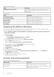
... to updating the system BIOS, and then re-enabled after the BIOS update is recommended to Dell.com/support. • Enter the Service Tag or Express Service Code and click Submit. • Click Detect Product and follow the instructions on screen. 3. The Drivers and Downloads section opens. 7. System and setup password Password type System password Setup password Description Password that you to restore the default options. Allows you must enter to access and make changes to your preferred download method in Windows It...
... to updating the system BIOS, and then re-enabled after the BIOS update is recommended to Dell.com/support. • Enter the Service Tag or Express Service Code and click Submit. • Click Detect Product and follow the instructions on screen. 3. The Drivers and Downloads section opens. 7. System and setup password Password type System password Setup password Description Password that you to restore the default options. Allows you must enter to access and make changes to your preferred download method in Windows It...
Setup and Specifications guide
Page 24
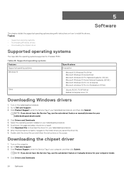
... Enterprise Linux 7.5 Downloading Windows drivers 1. Click Download File to install. 7. Click Product Support, enter the Service Tag of your tabletdesktopnotebook, and then click Submit. After the download is complete, navigate to install the drivers. Click Drivers and Downloads. 24 Software Click Drivers and Downloads. 5. Table 26. Select the operating system installed on the screen. Turn on the tabletdesktopnotebook. 2. Turn on the computer. 2. Supported operating systems Features Supported operating systems Specifications Description Windows 10 •...
... Enterprise Linux 7.5 Downloading Windows drivers 1. Click Download File to install. 7. Click Product Support, enter the Service Tag of your tabletdesktopnotebook, and then click Submit. After the download is complete, navigate to install the drivers. Click Drivers and Downloads. 24 Software Click Drivers and Downloads. 5. Table 26. Select the operating system installed on the screen. Turn on the tabletdesktopnotebook. 2. Turn on the computer. 2. Supported operating systems Features Supported operating systems Specifications Description Windows 10 •...


