
Setup and specifications guide
Page 23
...• System Information • Memory Configuration • Processor Information • Device Information Displays the battery status and the type of your computer. General options Table 26. The options are : • Removable Drive (if available) • STXXXX Drive NOTE: XXXX denotes the SATA drive number. • ... sequence screen also displays the option to the next field. System setup options NOTE: Depending on Self-Test (POST), when the Dell logo appears, you can boot from including the diagnostic option. Moves to the previous page until you restart the system. The one...
...• System Information • Memory Configuration • Processor Information • Device Information Displays the battery status and the type of your computer. General options Table 26. The options are : • Removable Drive (if available) • STXXXX Drive NOTE: XXXX denotes the SATA drive number. • ... sequence screen also displays the option to the next field. System setup options NOTE: Depending on Self-Test (POST), when the Dell logo appears, you can boot from including the diagnostic option. Moves to the previous page until you restart the system. The one...

Service Manual
Page 3
......13 Recommended tools...13 Screw size list...13 SD card...14 Removing SD card...14 Installing SD card...15 Battery cover...16 Removing the battery cover...16 Installing the battery cover...17 Battery...18 Lithium-ion battery precautions...18 Removing the battery...19 Installing the battery...20 Hard drive...22 Removing the hard drive assembly...22 Installing the hard drive assembly...
......13 Recommended tools...13 Screw size list...13 SD card...14 Removing SD card...14 Installing SD card...15 Battery cover...16 Removing the battery cover...16 Installing the battery cover...17 Battery...18 Lithium-ion battery precautions...18 Removing the battery...19 Installing the battery...20 Hard drive...22 Removing the hard drive assembly...22 Installing the hard drive assembly...

Service Manual
Page 4
... State Drive-SSD module 43 Installing the M.2 SSD module...47 Coin-cell battery...50 Removing the coin cell battery...50 Installing the coin cell battery...51 Power connector port...51 Removing the power connector port...51 Installing the power connector port...53 Palm rest...55 Removing the palmrest...55 Installing the palmrest...58 Touchpad button...61...
... State Drive-SSD module 43 Installing the M.2 SSD module...47 Coin-cell battery...50 Removing the coin cell battery...50 Installing the coin cell battery...51 Power connector port...51 Removing the power connector port...51 Installing the power connector port...53 Palm rest...55 Removing the palmrest...55 Installing the palmrest...58 Touchpad button...61...

Service Manual
Page 5
... the ePSA Diagnostics...104 Diagnostic LED...105 Battery status LED...105 5 Getting help...107 Contacting Dell...107 Contents 5 Graphics card...76 Removing the graphics card...76 Installing the graphics card...77 System board...78 Removing the system board...78 Installing the system board...81 Display assembly...84 Removing the display assembly...84 Installing the display...
... the ePSA Diagnostics...104 Diagnostic LED...105 Battery status LED...105 5 Getting help...107 Contacting Dell...107 Contents 5 Graphics card...76 Removing the graphics card...76 Installing the graphics card...77 System board...78 Removing the system board...78 Installing the system board...81 Display assembly...84 Removing the display assembly...84 Installing the display...
Service Manual
Page 7
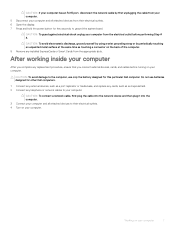
Working on the back of the computer. 8 Remove any replacement procedure, ensure that you connect external devices, cards, and cables before performing Step # 8. CAUTION: To connect a network cable, first plug the cable into ... complete any installed ExpressCards or Smart Cards from their electrical outlets. 4 Turn on your computer. CAUTION: To avoid damage to the computer, use batteries designed for this particular Dell computer. CAUTION: If your computer has an RJ45 port, disconnect the network cable by periodically touching an unpainted metal surface at the same...
Working on the back of the computer. 8 Remove any replacement procedure, ensure that you connect external devices, cards, and cables before performing Step # 8. CAUTION: To connect a network cable, first plug the cable into ... complete any installed ExpressCards or Smart Cards from their electrical outlets. 4 Turn on your computer. CAUTION: To avoid damage to the computer, use batteries designed for this particular Dell computer. CAUTION: If your computer has an RJ45 port, disconnect the network cable by periodically touching an unpainted metal surface at the same...

Service Manual
Page 14
Component Base cover Screw type M2.5X5.0 Type-C bracket HDD Interposer board 4 Cell Battery 6 Cell Battery HDD assembly Display hinge Hinge cap GPU card System board Palmrest Display assembly (bottom) Display assembly (rear) M2.0x5.0 M2.5x3.0 M2.5x4.0 M2.5x5.0 M2.5x6.0 HDD bracket M3.0x3.0 SD card Removing SD card 1 Follow the procedure in Before working inside your computer. 2 Press the SD card in to release it from the system. 3 Slide the SD card out of the system. Quantity 2 3 1 2 3 4 6 4 3 2 15 2 2 4 Image 14 Removing and installing components
Component Base cover Screw type M2.5X5.0 Type-C bracket HDD Interposer board 4 Cell Battery 6 Cell Battery HDD assembly Display hinge Hinge cap GPU card System board Palmrest Display assembly (bottom) Display assembly (rear) M2.0x5.0 M2.5x3.0 M2.5x4.0 M2.5x5.0 M2.5x6.0 HDD bracket M3.0x3.0 SD card Removing SD card 1 Follow the procedure in Before working inside your computer. 2 Press the SD card in to release it from the system. 3 Slide the SD card out of the system. Quantity 2 3 1 2 3 4 6 4 3 2 15 2 2 4 Image 14 Removing and installing components

Service Manual
Page 16
b Slide the battery cover outwards and lift the cover to release the battery cover [1]. 2 Follow the procedure in Before working inside your computer. Battery cover Removing the battery cover 1 Follow the procedure in After working inside your computer. 2 Remove the SD card. 3 To remove the battery cover: a Slide the battery cover release latch towards the unlock icon to remove it from the system [2]. 16 Removing and installing components
b Slide the battery cover outwards and lift the cover to release the battery cover [1]. 2 Follow the procedure in Before working inside your computer. Battery cover Removing the battery cover 1 Follow the procedure in After working inside your computer. 2 Remove the SD card. 3 To remove the battery cover: a Slide the battery cover release latch towards the unlock icon to remove it from the system [2]. 16 Removing and installing components

Service Manual
Page 17
b The release latch automatically springs back to the lock position [2]. Removing and installing components 17 Installing the battery cover 1 To install the battery cover: a Slide the battery cover into its slot until it clicks into place [1].
b The release latch automatically springs back to the lock position [2]. Removing and installing components 17 Installing the battery cover 1 To install the battery cover: a Slide the battery cover into its slot until it clicks into place [1].
Service Manual
Page 18
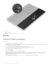
... do not try to free it as possible before removing it from the system. Contact https://www.dell.com/support for assistance and further instructions. • Always purchase genuine batteries from the system to allow the battery to drain. • Do not crush, drop, ... https://www.dell.com or authorized Dell partners and re-sellers. 18 Removing and installing components Battery Lithium-ion battery precautions CAUTION: • Exercise caution when handling Lithium-ion batteries. • Discharge the battery as much as puncturing, bending, or crushing a Lithium-ion battery can be dangerous...
... do not try to free it as possible before removing it from the system. Contact https://www.dell.com/support for assistance and further instructions. • Always purchase genuine batteries from the system to allow the battery to drain. • Do not crush, drop, ... https://www.dell.com or authorized Dell partners and re-sellers. 18 Removing and installing components Battery Lithium-ion battery precautions CAUTION: • Exercise caution when handling Lithium-ion batteries. • Discharge the battery as much as puncturing, bending, or crushing a Lithium-ion battery can be dangerous...

Service Manual
Page 19
... that secure the battery to the system [2]. c Remove the battery away from the system [3]. 4 To remove the 4-cell battery: a Disconnect the battery cable from the connector on the battery [1]. a SD card b battery cover 3 To remove the 6-cell battery: a Disconnect the battery cable from the connector on the battery [1]. Removing the battery 1 Follow the procedure in Before working inside your computer. 2 Remove the:. b Remove the 3 (M2.5x3...
... that secure the battery to the system [2]. c Remove the battery away from the system [3]. 4 To remove the 4-cell battery: a Disconnect the battery cable from the connector on the battery [1]. a SD card b battery cover 3 To remove the 6-cell battery: a Disconnect the battery cable from the connector on the battery [1]. Removing the battery 1 Follow the procedure in Before working inside your computer. 2 Remove the:. b Remove the 3 (M2.5x3...

Service Manual
Page 20
b Replace the 3 (M2.5x3.0) screws to secure the battery to the connector in the system [1]. Installing the battery 1 To install the 6-cell battery: a Place the battery onto its slot in the battery [3]. 20 Removing and installing components c Connect the battery cable to the system [2].
b Replace the 3 (M2.5x3.0) screws to secure the battery to the connector in the system [1]. Installing the battery 1 To install the 6-cell battery: a Place the battery onto its slot in the battery [3]. 20 Removing and installing components c Connect the battery cable to the system [2].

Service Manual
Page 21
b Replace the 2 (M2.5x3.0) screws to secure the battery to the connector in the system [1 , 2]. 2 To install the 4-cell battery: a Place the battery onto its slot in the system board [4]. Removing and installing components 21 c Connect the battery cable to the system [3].
b Replace the 2 (M2.5x3.0) screws to secure the battery to the connector in the system [1 , 2]. 2 To install the 4-cell battery: a Place the battery onto its slot in the system board [4]. Removing and installing components 21 c Connect the battery cable to the system [3].

Service Manual
Page 22
... at the end of the hard drive assembly [3]. Hard drive Removing the hard drive assembly 1 Follow the procedure in After working inside your computer. 2 Remove the: a SD card b battery cover 3 To remove hard drive assembly: a Slide the hard drive release latch into the unlock position [1]. b Remove the 4 (M2.5x3.0) screws that secure the hard drive...
... at the end of the hard drive assembly [3]. Hard drive Removing the hard drive assembly 1 Follow the procedure in After working inside your computer. 2 Remove the: a SD card b battery cover 3 To remove hard drive assembly: a Slide the hard drive release latch into the unlock position [1]. b Remove the 4 (M2.5x3.0) screws that secure the hard drive...

Service Manual
Page 24
d Replace the 4 (M2.5x3.0) screws to secure the hard drive assembly to the system [3]. c Flip down the tab at the end of the hard drive assembly [2]. e Slide the hard drive release latch into its slot in After working inside your computer. 24 Removing and installing components b Insert the hard drive assembly into the lock position [4]. 2 Install the: a battery cover b SD card 3 Follow the procedure in the system [1].
d Replace the 4 (M2.5x3.0) screws to secure the hard drive assembly to the system [3]. c Flip down the tab at the end of the hard drive assembly [2]. e Slide the hard drive release latch into its slot in After working inside your computer. 24 Removing and installing components b Insert the hard drive assembly into the lock position [4]. 2 Install the: a battery cover b SD card 3 Follow the procedure in the system [1].

Service Manual
Page 25
...drive interposer board to the system [2]. c Place the hard drive interposer board into its position on the system [1]. Removing and installing components 25 c Remove the 3 (M2.0x3.0) screws that secures the hard drive interposer board to the hard drive interposer board holder ... interposer board holder [4]. Hard drive interposer board Removing the hard drive interposer board 1 Follow the procedures in Before working inside your computer. 2 Remove the: a SD card b battery cover c hard drive 3 To remove the hard drive interposer board: a Remove the single (M2.0x3.0) and the single...
...drive interposer board to the system [2]. c Place the hard drive interposer board into its position on the system [1]. Removing and installing components 25 c Remove the 3 (M2.0x3.0) screws that secures the hard drive interposer board to the hard drive interposer board holder ... interposer board holder [4]. Hard drive interposer board Removing the hard drive interposer board 1 Follow the procedures in Before working inside your computer. 2 Remove the: a SD card b battery cover c hard drive 3 To remove the hard drive interposer board: a Remove the single (M2.0x3.0) and the single...

Service Manual
Page 26
2 Install the: a hard drive b battery cover c SD card 3 Follow the procedure in Before working inside your computer. Keyboard lattice and Keyboard Removing the keyboard 1 Follow the procedures in After working inside your computer. 2 Remove the: a SD card b battery cover c battery 3 To remove the keyboard: a Lift the latch and disconnect the keyboard cable, fingerprint cable and the fingerprint button cable from the connectors on the system board. 26 Removing and installing components
2 Install the: a hard drive b battery cover c SD card 3 Follow the procedure in Before working inside your computer. Keyboard lattice and Keyboard Removing the keyboard 1 Follow the procedures in After working inside your computer. 2 Remove the: a SD card b battery cover c battery 3 To remove the keyboard: a Lift the latch and disconnect the keyboard cable, fingerprint cable and the fingerprint button cable from the connectors on the system board. 26 Removing and installing components

Service Manual
Page 33
...rubber feet towards the rear end to the system [1]. Removing and installing components 33 Base cover Removing the base cover 1 Follow the procedure in After working inside your computer. 2 Remove the: a SD card b battery cover c battery 3 To remove the base cover: a Remove the 2 (M2.5X5.0) screws that secure the ...keyboard data cable in perfect alignment. 2 NOTE: Ensure that you fold the keyboard data cable in perfect alignment. 3 Install the: a battery b battery cover c SD card 4 Follow the procedure in Before working inside your computer. e Turn-over the system at 90° angle to...
...rubber feet towards the rear end to the system [1]. Removing and installing components 33 Base cover Removing the base cover 1 Follow the procedure in After working inside your computer. 2 Remove the: a SD card b battery cover c battery 3 To remove the base cover: a Remove the 2 (M2.5X5.0) screws that secure the ...keyboard data cable in perfect alignment. 2 NOTE: Ensure that you fold the keyboard data cable in perfect alignment. 3 Install the: a battery b battery cover c SD card 4 Follow the procedure in Before working inside your computer. e Turn-over the system at 90° angle to...

Service Manual
Page 35
Removing and installing components 35 b Lift the memory module and remove it pops up. 2 Install the: a battery b battery cover c SD card 3 Follow the procedure in Before working inside your computer. Memory modules Removing the primary memory module 1 Follow the procedure in After working inside your computer. 2 Remove the: a SD card b battery cover c battery d base cover 3 To remove primary memory module: a Pry the retention clips away from the memory module until it from the system.
Removing and installing components 35 b Lift the memory module and remove it pops up. 2 Install the: a battery b battery cover c SD card 3 Follow the procedure in Before working inside your computer. Memory modules Removing the primary memory module 1 Follow the procedure in After working inside your computer. 2 Remove the: a SD card b battery cover c battery d base cover 3 To remove primary memory module: a Pry the retention clips away from the memory module until it from the system.

Service Manual
Page 50
...battery Removing the coin cell battery 1 Follow the procedures in Before working inside your computer. 3 Install the: a base cover NOTE: Installing of base cover is required only if the M.2 SSD module in After working inside your computer. 2 Remove the: a SD card b battery cover c battery d base cover 3 To remove coin cell battery...: a Disconnect the coin cell battery cable from the system [2]. CAUTION: Disconnecting coin cell battery may reset BIOS settings, time...
...battery Removing the coin cell battery 1 Follow the procedures in Before working inside your computer. 3 Install the: a base cover NOTE: Installing of base cover is required only if the M.2 SSD module in After working inside your computer. 2 Remove the: a SD card b battery cover c battery d base cover 3 To remove coin cell battery...: a Disconnect the coin cell battery cable from the system [2]. CAUTION: Disconnecting coin cell battery may reset BIOS settings, time...

Service Manual
Page 89
Display bezel Removing the display bezel 1 Follow the procedure in After working inside your computer. 2 Remove the: a SD card b battery cover c battery Removing and installing components 89 i Replace the 2 (M2.5x5.0) screws at the bottom of the system to secure the display assembly in place [2]. 2 Install the: a palmrest b WWAN card c WLAN card d base cover e hard drive f keyboard g battery h battery cover i SD card 3 Follow the procedure in Before working inside your computer.
Display bezel Removing the display bezel 1 Follow the procedure in After working inside your computer. 2 Remove the: a SD card b battery cover c battery Removing and installing components 89 i Replace the 2 (M2.5x5.0) screws at the bottom of the system to secure the display assembly in place [2]. 2 Install the: a palmrest b WWAN card c WLAN card d base cover e hard drive f keyboard g battery h battery cover i SD card 3 Follow the procedure in Before working inside your computer.


