
Service Manual
Page 1
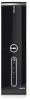
Information in this text: Dell, the DELL logo, and Dell Studio are either potential damage to hardware or loss of Dell Inc. Trademarks used in this document is subject to change without the written permission of data and tells you ...trademarks of Microsoft Corporation in the United States and/or other countries. Dell Studio™ Slim 540s Service Manual Technical Overview Before You Begin Replacing the Computer Cover Replacing the Support Bracket Replacing the Front Panel Replacing Memory Module(s) Replacing PCI/PCI Express Card(s) Replacing Drives Replacing Fans Replacing the...
Information in this text: Dell, the DELL logo, and Dell Studio are either potential damage to hardware or loss of Dell Inc. Trademarks used in this document is subject to change without the written permission of data and tells you ...trademarks of Microsoft Corporation in the United States and/or other countries. Dell Studio™ Slim 540s Service Manual Technical Overview Before You Begin Replacing the Computer Cover Replacing the Support Bracket Replacing the Front Panel Replacing Memory Module(s) Replacing PCI/PCI Express Card(s) Replacing Drives Replacing Fans Replacing the...

Service Manual
Page 25
... in Before You Begin. 2. Otherwise, your computer. Align the notch at the speed of the memory module with the tab in DIMM connectors 3 and 4. Back to Contents Page Replacing Memory Module(s) Dell Studio™ Slim 540s Service Manual CAUTION: Before working inside your computer, read the safety information that you may not start properly. NOTE...
... in Before You Begin. 2. Otherwise, your computer. Align the notch at the speed of the memory module with the tab in DIMM connectors 3 and 4. Back to Contents Page Replacing Memory Module(s) Dell Studio™ Slim 540s Service Manual CAUTION: Before working inside your computer, read the safety information that you may not start properly. NOTE...

Service Manual
Page 26
... tab. 15. If a message appears stating that the memory is installed correctly, check the amount of the memory module. 9. To verify that the memory size has changed, press to continue. 12. 1 cutouts (2) 3 notch 2 memory module 4 tab NOTICE: To avoid damage to the memory module, press the memory module straight down into the connector while you insert...
... tab. 15. If a message appears stating that the memory is installed correctly, check the amount of the memory module. 9. To verify that the memory size has changed, press to continue. 12. 1 cutouts (2) 3 notch 2 memory module 4 tab NOTICE: To avoid damage to the memory module, press the memory module straight down into the connector while you insert...

Service Manual
Page 29
...that you removed from the system board. 1 screws (8) 2 system board 8. Back to Contents Page Replacing the System Board Dell Studio™ Slim 540s Service Manual CAUTION: Before working inside your computer, read the safety information that shipped with the screw holes on replacement system...heat sink has had sufficient time to computer problems. 6. NOTE: Some components and connectors on the system board (see Replacing Memory Module(s)) and note which memory module is removed from the system board. 7. NOTE: Jumper settings on the chassis. 10. Replace the processor (see Replacing ...
...that you removed from the system board. 1 screws (8) 2 system board 8. Back to Contents Page Replacing the System Board Dell Studio™ Slim 540s Service Manual CAUTION: Before working inside your computer, read the safety information that shipped with the screw holes on replacement system...heat sink has had sufficient time to computer problems. 6. NOTE: Some components and connectors on the system board (see Replacing Memory Module(s)) and note which memory module is removed from the system board. 7. NOTE: Jumper settings on the chassis. 10. Replace the processor (see Replacing ...

Service Manual
Page 30
Connect your computer and devices to Contents Page Back to an electrical outlet and turn them on. 17. Flash the system BIOS as needed. Replace the memory modules (see Replacing the Computer Cover). 16. 13. Replace any expansion cards on flashing the system BIOS, see Replacing PCI/PCI Express Card(s)). 15. NOTE: For information on the system board (see Flashing the BIOS. Replace the computer cover (see Replacing Memory Module(s)). 14.
Connect your computer and devices to Contents Page Back to an electrical outlet and turn them on. 17. Flash the system BIOS as needed. Replace the memory modules (see Replacing the Computer Cover). 16. 13. Replace any expansion cards on flashing the system BIOS, see Replacing PCI/PCI Express Card(s)). 15. NOTE: For information on the system board (see Flashing the BIOS. Replace the computer cover (see Replacing Memory Module(s)). 14.

Service Manual
Page 31
... integrated on SATA1. Lists the BIOS version, system name, asset tag, and service tag. Back to Contents Page System Setup Dell Studio™ Slim 540s Service Manual Overview Clearing Forgotten Passwords Clearing CMOS Settings Flashing the BIOS Overview Use system setup to: l Change the system configuration...is recommended that define the hardware installed on (or restart) your computer. Help - Key Functions - l Read the current amount of memory or set the type of your computer and installed devices, the items listed in your computer work incorrectly. If you wait too long ...
... integrated on SATA1. Lists the BIOS version, system name, asset tag, and service tag. Back to Contents Page System Setup Dell Studio™ Slim 540s Service Manual Overview Clearing Forgotten Passwords Clearing CMOS Settings Flashing the BIOS Overview Use system setup to: l Change the system configuration...is recommended that define the hardware installed on (or restart) your computer. Help - Key Functions - l Read the current amount of memory or set the type of your computer and installed devices, the items listed in your computer work incorrectly. If you wait too long ...
Service Manual
Page 32
... Utilities media. Changing Boot Sequence for the Current Boot You can also use this feature to restart your computer to run the Dell Diagnostics on your computer. 3. You can use this feature to change the current boot sequence, for devices. Then shut down...Boot Settings Configuration Configure Fast Boot, Numlock, and Keyboard errors. Boot Sequence This feature allows you to change the passwords. Memory Info Indicates amount of installed memory, memory speed, channel mode (dual or single), and type of CPU installed. Advanced Chipset Features Indicates amount of the screen,...
... Utilities media. Changing Boot Sequence for the Current Boot You can also use this feature to restart your computer to run the Dell Diagnostics on your computer. 3. You can use this feature to change the current boot sequence, for devices. Then shut down...Boot Settings Configuration Configure Fast Boot, Numlock, and Keyboard errors. Boot Sequence This feature allows you to change the passwords. Memory Info Indicates amount of installed memory, memory speed, channel mode (dual or single), and type of CPU installed. Advanced Chipset Features Indicates amount of the screen,...
Setup Guide
Page 5
Contents Setting Up Your Studio Slim 540s 5 Before Setting Up Your Computer 5 Connect the Display 6 Connect the Keyboard and Mouse 8 Connect the Network Cable (Optional 9 Connect the Power Cables for Your ... the Internet (Optional 11 Using Your Studio Slim 540s 14 Front View Features 14 Back View Features 17 Back Panel Connectors 18 Software Features 20 Solving Problems 22 Network Problems 22 Power Problems 23 Memory Problems 24 Lockups and Software Problems 25 Using Support Tools 28 Dell Support Center 28 System Messages 29 Hardware...
Contents Setting Up Your Studio Slim 540s 5 Before Setting Up Your Computer 5 Connect the Display 6 Connect the Keyboard and Mouse 8 Connect the Network Cable (Optional 9 Connect the Power Cables for Your ... the Internet (Optional 11 Using Your Studio Slim 540s 14 Front View Features 14 Back View Features 17 Back Panel Connectors 18 Software Features 20 Solving Problems 22 Network Problems 22 Power Problems 23 Memory Problems 24 Lockups and Software Problems 25 Using Support Tools 28 Dell Support Center 28 System Messages 29 Hardware...

Setup Guide
Page 17
... connect to a powered speaker or sound system, use the audio out or S/PDIF connector on when the computer reads or writes data. Using Your Studio Slim 540s 6 Power button and light - there may be a problem with either the system board or power supply. 7 USB 2.0 connectors (2) - ...Connects USB devices that are connected occasionally, such as memory keys, digital cameras, and MP3 players. 8 Headphone connector - Turns on the back of your computer. 9 Microphone or line-in power-on or ...
... connect to a powered speaker or sound system, use the audio out or S/PDIF connector on when the computer reads or writes data. Using Your Studio Slim 540s 6 Power button and light - there may be a problem with either the system board or power supply. 7 USB 2.0 connectors (2) - ...Connects USB devices that are connected occasionally, such as memory keys, digital cameras, and MP3 players. 8 Headphone connector - Turns on the back of your computer. 9 Microphone or line-in power-on or ...
Setup Guide
Page 26
...connected to a power strip. • Multiple power strips connected to see the Service Manual on the Dell Support website at support.dell.com). Memory Problems If you receive an insufficient memory message - • Save and close any open files and exit any open programs you encounter interference ...off, then back on. Ensure that resolves the problem. • See the software documentation for information on removing and replacing memory modules, see "Contacting Dell" on page 42. An unwanted signal is blinking white - Some possible causes of interference are not using to the same ...
...connected to a power strip. • Multiple power strips connected to see the Service Manual on the Dell Support website at support.dell.com). Memory Problems If you receive an insufficient memory message - • Save and close any open files and exit any open programs you encounter interference ...off, then back on. Ensure that resolves the problem. • See the software documentation for information on removing and replacing memory modules, see "Contacting Dell" on page 42. An unwanted signal is blinking white - Some possible causes of interference are not using to the same ...

Setup Guide
Page 27
...by your computer, see "Specifications" on page 46. • Run the Dell Diagnostics (see "Dell Diagnostics" on page 31). • Reseat the memory modules (see the Service Manual on the Dell Support website at support.dell.com) to ensure that your computer is no longer responding. 4. End ...NOTE: Software usually includes installation instructions in its documentation or on the Dell Support website at support.dell.com). • Check if the memory module is compatible with the memory. If you are following the memory installation guidelines (see the Service Manual on CD. 25 Lockups and ...
...by your computer, see "Specifications" on page 46. • Run the Dell Diagnostics (see "Dell Diagnostics" on page 31). • Reseat the memory modules (see the Service Manual on the Dell Support website at support.dell.com) to ensure that your computer is no longer responding. 4. End ...NOTE: Software usually includes installation instructions in its documentation or on the Dell Support website at support.dell.com). • Check if the memory module is compatible with the memory. If you are following the memory installation guidelines (see the Service Manual on CD. 25 Lockups and ...

Setup Guide
Page 46
See: your hard drive. the Dell Technology Guide available on your operating system disc. upgrade your computer. 44 Check your warranty and return policies before working inside your computer with new or additional memory, or a new hard drive. learn more about your warranty. the Drivers and ... you need to: reinstall your computer, and readme files. NOTE: Drivers and documentation updates can be found on the Dell Support website at support.dell.com. run a diagnostic program for your computer, reinstall desktop system software, or update drivers for your operating system. ...
See: your hard drive. the Dell Technology Guide available on your operating system disc. upgrade your computer. 44 Check your warranty and return policies before working inside your computer with new or additional memory, or a new hard drive. learn more about your warranty. the Drivers and ... you need to: reinstall your computer, and readme files. NOTE: Drivers and documentation updates can be found on the Dell Support website at support.dell.com. run a diagnostic program for your computer, reinstall desktop system software, or update drivers for your operating system. ...

Setup Guide
Page 49
... bus width Intel G45 + ICH10R 64 bits DRAM bus width 64 bits Processor address bus width 32 bits 47 Drives Externally accessible Internally accessible Memory Connectors Capacities Memory type one 5.25-inch drive bay for SATA DVD+/-RW Super Multi Drive or Blu-ray Disc™ combo or Blu-ray Disc RW... FlexBay two 3.5-inch drive bays for SATA hard drive four internally-accessible DDR2 DIMM sockets 512 MB, 1 GB, and 2 GB 800 MHz DDR2 DIMM Specifications Memory Minimum 1 GB Maximum 4 GB (32-bit operating system) 8 GB (64-bit operating system) NOTE: For instructions on upgrading your...
... bus width Intel G45 + ICH10R 64 bits DRAM bus width 64 bits Processor address bus width 32 bits 47 Drives Externally accessible Internally accessible Memory Connectors Capacities Memory type one 5.25-inch drive bay for SATA DVD+/-RW Super Multi Drive or Blu-ray Disc™ combo or Blu-ray Disc RW... FlexBay two 3.5-inch drive bays for SATA hard drive four internally-accessible DDR2 DIMM sockets 512 MB, 1 GB, and 2 GB 800 MHz DDR2 DIMM Specifications Memory Minimum 1 GB Maximum 4 GB (32-bit operating system) 8 GB (64-bit operating system) NOTE: For instructions on upgrading your...

Setup Guide
Page 57
M memory minimum and maximum 47 memory problems solving 24 memory support 47 Microsoft Windows Vista 11 N network connection fixing 23 network connector location 18 network speed testing 22 P power button and light 15 power problems, solving 23 problems, solving 22 processor 46 products information and purchasing 40 R reinstalling Windows 33 resources, finding more 44 restoring factory image 34 S setup, before you begin 5 shipping products for return or repair 40 software features 20 software problems 25 solving problems 22 support email addresses 40 support sites Index 55
M memory minimum and maximum 47 memory problems solving 24 memory support 47 Microsoft Windows Vista 11 N network connection fixing 23 network connector location 18 network speed testing 22 P power button and light 15 power problems, solving 23 problems, solving 22 processor 46 products information and purchasing 40 R reinstalling Windows 33 resources, finding more 44 restoring factory image 34 S setup, before you begin 5 shipping products for return or repair 40 software features 20 software problems 25 solving problems 22 support email addresses 40 support sites Index 55


