User Manual
Page 1
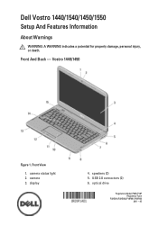
Vostro 1440/1450 Figure 1. speakers (2) 5. camera 3. optical drive Regulatory Model P22G,P18F Regulatory Type P22G001,P22G003,P18F001,P18F002 2011 - 05 Front View 1. USB 2.0 connectors (2) 6. display 4. camera status light 2. Front And Back - Dell Vostro 1440/1540/1450/1550 Setup And Features Information About Warnings WARNING: A WARNING indicates a potential for property damage, personal injury, or death.
Vostro 1440/1450 Figure 1. speakers (2) 5. camera 3. optical drive Regulatory Model P22G,P18F Regulatory Type P22G001,P22G003,P18F001,P18F002 2011 - 05 Front View 1. USB 2.0 connectors (2) 6. display 4. camera status light 2. Front And Back - Dell Vostro 1440/1540/1450/1550 Setup And Features Information About Warnings WARNING: A WARNING indicates a potential for property damage, personal injury, or death.
User Manual
Page 2
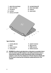
...power button Figure 2. security cable slot 2. audio connectors 9. keyboard 15. battery 3. Restricting the airflow can damage the computer or cause a fire. The computer turns on the fan when the computer gets hot. microphone 10. HDMI connector 8. touchpad buttons (2) 13. device status lights 14. cooling vents 5. memory card reader 12. USB... indicate a problem with the fan or the computer. 2 power connector 4. Do not store your Dell computer in the air vents. Fan noise is running. 7. optical drive eject button 8. touchpad 11. Back View 1. network ...
...power button Figure 2. security cable slot 2. audio connectors 9. keyboard 15. battery 3. Restricting the airflow can damage the computer or cause a fire. The computer turns on the fan when the computer gets hot. microphone 10. HDMI connector 8. touchpad buttons (2) 13. device status lights 14. cooling vents 5. memory card reader 12. USB... indicate a problem with the fan or the computer. 2 power connector 4. Do not store your Dell computer in the air vents. Fan noise is running. 7. optical drive eject button 8. touchpad 11. Back View 1. network ...
User Manual
Page 3
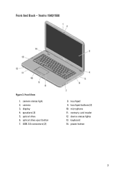
camera 3. optical drive 6. USB 2.0 connectors (2) 8. touchpad buttons (2) 10. keyboard 14. camera status light 2. optical drive eject button 7. power button 3 touchpad 9. memory card reader 12. speakers (2) 5. Front And Back - microphone 11. Front View 1. device status lights 13. display 4. Vostro 1540/1550 Figure 3.
camera 3. optical drive 6. USB 2.0 connectors (2) 8. touchpad buttons (2) 10. keyboard 14. camera status light 2. optical drive eject button 7. power button 3 touchpad 9. memory card reader 12. speakers (2) 5. Front And Back - microphone 11. Front View 1. device status lights 13. display 4. Vostro 1540/1550 Figure 3.

User Manual
Page 4
security cable slot 2. cooling vents 5. WARNING: The AC adapter works with your Dell computer in the air vents. However, power connectors and power strips vary among countries. power connector 4. HDMI connector 8. USB 2.0 connector 9. Fan noise is running. network connector 6. audio connectors WARNING: Do not block, push objects into, or allow dust to the power strip or electrical outlet may cause fire or equipment damage. 4 Quick Setup WARNING...
security cable slot 2. cooling vents 5. WARNING: The AC adapter works with your Dell computer in the air vents. However, power connectors and power strips vary among countries. power connector 4. HDMI connector 8. USB 2.0 connector 9. Fan noise is running. network connector 6. audio connectors WARNING: Do not block, push objects into, or allow dust to the power strip or electrical outlet may cause fire or equipment damage. 4 Quick Setup WARNING...
User Manual
Page 6
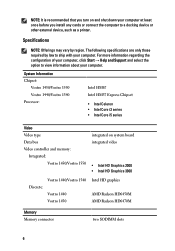
... regarding the configuration of your computer, click Start → Help and Support and select the option to a docking device or other external device, such as a printer. System Information Chipset: Vostro 1450/Vostro 1550 Vostro 1440/Vostro 1540 Processor: Intel HM67 Intel HM57 Express Chipset • Intel Celeron • Intel Core i3 series • Intel Core i5 series Video Video type Data bus Video controller and memory: Integrated: Vostro 1450/Vostro 1550 integrated on...
... regarding the configuration of your computer, click Start → Help and Support and select the option to a docking device or other external device, such as a printer. System Information Chipset: Vostro 1450/Vostro 1550 Vostro 1440/Vostro 1540 Processor: Intel HM67 Intel HM57 Express Chipset • Intel Celeron • Intel Core i3 series • Intel Core i5 series Video Video type Data bus Video controller and memory: Integrated: Vostro 1450/Vostro 1550 integrated on...

Owners Manual
Page 3
... Working Inside Your Computer 7 Recommended Tools...8 Turning Off Your Computer 9 After Working Inside Your Computer 9 2 Removing The Battery 11 Installing The Battery...11 3 Removing The Secure Digital (SD) Card 13 Installing The Secure Digital (SD) Card 14 4 Removing The Hinge Cover 15 Installing The Hinge Cover 16 5 Removing The Keyboard 17 Installing The Keyboard 18 6 Removing The Optical Disc Drive 19 Installing The Optical Disc Drive 20 7 Removing The Memory Module 21 Installing The Memory Module 22 8 Removing The Palm Rest 23 Installing...
... Working Inside Your Computer 7 Recommended Tools...8 Turning Off Your Computer 9 After Working Inside Your Computer 9 2 Removing The Battery 11 Installing The Battery...11 3 Removing The Secure Digital (SD) Card 13 Installing The Secure Digital (SD) Card 14 4 Removing The Hinge Cover 15 Installing The Hinge Cover 16 5 Removing The Keyboard 17 Installing The Keyboard 18 6 Removing The Optical Disc Drive 19 Installing The Optical Disc Drive 20 7 Removing The Memory Module 21 Installing The Memory Module 22 8 Removing The Palm Rest 23 Installing...

Owners Manual
Page 4
9 Removing The Power Button Board 27 Installing The Power Button Board 28 10 Removing The Hard Drive 29 Installing The Hard Drive 30 11 Removing The Wireless Local Area Network (WLAN) Card...........31 Installing The Wireless Local Area Network (WLAN) Card 32 12 Removing The Coin-Cell Battery 33 Installing The Coin-Cell Battery 34 13 Removing The USB Board 35 Installing The USB Board 36 14 Removing The Microphone 37 Installing The Microphone 38 15 Removing The CPU Fan Assembly And The Heatsink 39 Installing The CPU Fan Assembly And The Heatsink...
9 Removing The Power Button Board 27 Installing The Power Button Board 28 10 Removing The Hard Drive 29 Installing The Hard Drive 30 11 Removing The Wireless Local Area Network (WLAN) Card...........31 Installing The Wireless Local Area Network (WLAN) Card 32 12 Removing The Coin-Cell Battery 33 Installing The Coin-Cell Battery 34 13 Removing The USB Board 35 Installing The USB Board 36 14 Removing The Microphone 37 Installing The Microphone 38 15 Removing The CPU Fan Assembly And The Heatsink 39 Installing The CPU Fan Assembly And The Heatsink...
Owners Manual
Page 7
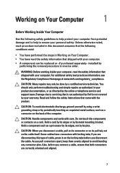
... the back of cable, press in this type of the computer. Also, before you pull connectors apart, keep them evenly aligned to ensure your warranty. You should only perform troubleshooting and simple repairs as directed by its pins. CAUTION: To avoid electrostatic discharge, ground yourself by using a wrist grounding strap or by periodically touching an unpainted metal...
... the back of cable, press in this type of the computer. Also, before you pull connectors apart, keep them evenly aligned to ensure your warranty. You should only perform troubleshooting and simple repairs as directed by its pins. CAUTION: To avoid electrostatic discharge, ground yourself by using a wrist grounding strap or by periodically touching an unpainted metal...

Owners Manual
Page 8
... your work surface is connected to ground the system board. Disconnect your computer, ground yourself by touching an unpainted metal surface, such as the optional Media Base or Battery Slice, undock it. NOTE: To avoid damaging the system board, you must remove the main battery before you work surface. Turn the computer top-side up. 9. Remove any installed ExpressCards or Smart Cards from the appropriate slots...
... your work surface is connected to ground the system board. Disconnect your computer, ground yourself by touching an unpainted metal surface, such as the optional Media Base or Battery Slice, undock it. NOTE: To avoid damaging the system board, you must remove the main battery before you work surface. Turn the computer top-side up. 9. Remove any installed ExpressCards or Smart Cards from the appropriate slots...
Owners Manual
Page 9
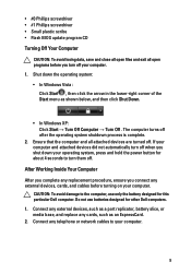
...; Flash BIOS update program CD Turning Off Your Computer CAUTION: To avoid losing data, save and close all open programs before turning on your operating system, press and hold the power button for about 4 seconds to turn them off. The computer turns off after the operating system shutdown process is complete. 2. Connect any external devices, such as a port replicator, battery slice, or media base, and replace any telephone or network cables...
...; Flash BIOS update program CD Turning Off Your Computer CAUTION: To avoid losing data, save and close all open programs before turning on your operating system, press and hold the power button for about 4 seconds to turn them off. The computer turns off after the operating system shutdown process is complete. 2. Connect any external devices, such as a port replicator, battery slice, or media base, and replace any telephone or network cables...

Owners Manual
Page 21
Remove the battery. 3. Pry the retention clips away from the computer. 21 Remove the memory module from the memory module until it pops up. 5. Removing The Memory Module 7 1. Follow the procedures in Before Working On Your Computer. 2. Remove the keyboard. 4.
Remove the battery. 3. Pry the retention clips away from the computer. 21 Remove the memory module from the memory module until it pops up. 5. Removing The Memory Module 7 1. Follow the procedures in Before Working On Your Computer. 2. Remove the keyboard. 4.

Owners Manual
Page 42
Ensure the processor is properly seated. 2. Install the palm rest. 5. Follow the procedures in a clockwise direction to the locked position. 3. Install the battery. 7. Tighten the cam-screw in After Working Inside Your Computer. 42 Installing The Processor 1. Insert the processor into the processor socket. Install the CPU fan assembly and the heatsink. 4. Install the keyboard. 6.
Ensure the processor is properly seated. 2. Install the palm rest. 5. Follow the procedures in a clockwise direction to the locked position. 3. Install the battery. 7. Tighten the cam-screw in After Working Inside Your Computer. 42 Installing The Processor 1. Insert the processor into the processor socket. Install the CPU fan assembly and the heatsink. 4. Install the keyboard. 6.

Owners Manual
Page 43
Removing The System Board 17 1. Follow the procedures in cable (2), USB board cable (3), speaker cable (4), audio board cable (5), and the coin-cell battery cable (6). 12. Remove the SD memory card. 4. Remove the optical drive. 6. Disconnect the display cable (1), DC-in Before Working On Your Computer. 2. Remove the battery. 3. Remove the WLAN card. 10. Remove the CPU fan assembly and the heatsink. 11. Remove the keyboard. 5. Remove the screws that secure the system board. 43 Remove the memory module. 7. Remove the palm rest. 8. Remove the hard drive. 9.
Removing The System Board 17 1. Follow the procedures in cable (2), USB board cable (3), speaker cable (4), audio board cable (5), and the coin-cell battery cable (6). 12. Remove the SD memory card. 4. Remove the optical drive. 6. Disconnect the display cable (1), DC-in Before Working On Your Computer. 2. Remove the battery. 3. Remove the WLAN card. 10. Remove the CPU fan assembly and the heatsink. 11. Remove the keyboard. 5. Remove the screws that secure the system board. 43 Remove the memory module. 7. Remove the palm rest. 8. Remove the hard drive. 9.

Owners Manual
Page 45
Install the processor. 5. Connect the LCD cable, DC-in place. 3. Install the SD memory card. 13. Install the battery. 14. Install the screws that secure the system board in cable, USB board cable, audio board cable, coin-cell battery cable, and the speaker cable. 4. Install the hard drive. 8. Install the keyboard. 12. Install the memory module. 10. Install the CPU fan assembly and the heatsink . 6. Install the palm rest. 9. Install the optical drive. 11. Installing The System Board 1. Install the WLAN card. 7. Insert the system board with the LAN, VGA, HDMI, and USB...
Install the processor. 5. Connect the LCD cable, DC-in place. 3. Install the SD memory card. 13. Install the battery. 14. Install the screws that secure the system board in cable, USB board cable, audio board cable, coin-cell battery cable, and the speaker cable. 4. Install the hard drive. 8. Install the keyboard. 12. Install the memory module. 10. Install the CPU fan assembly and the heatsink . 6. Install the palm rest. 9. Install the optical drive. 11. Installing The System Board 1. Install the WLAN card. 7. Insert the system board with the LAN, VGA, HDMI, and USB...

Owners Manual
Page 47
Removing The Speakers 1. Remove the optical drive. 6. Remove the SD memory card. 4. Remove the hard drive. 9. Remove the CPU fan assembly and the heatsink. 11. Release the speaker cable from the routing channel. 18 13. Press the securing latches and lift up the left speaker. 47 Remove the keyboard. 5. Remove the battery. 3. Remove the palm rest. 8. Remove the system board. 12. Remove the memory module. 7. Follow the procedures in Before Working On Your Computer. 2. Remove the WLAN card. 10.
Removing The Speakers 1. Remove the optical drive. 6. Remove the SD memory card. 4. Remove the hard drive. 9. Remove the CPU fan assembly and the heatsink. 11. Release the speaker cable from the routing channel. 18 13. Press the securing latches and lift up the left speaker. 47 Remove the keyboard. 5. Remove the battery. 3. Remove the palm rest. 8. Remove the system board. 12. Remove the memory module. 7. Follow the procedures in Before Working On Your Computer. 2. Remove the WLAN card. 10.
Owners Manual
Page 71
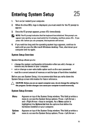
... the System Setup screen information for the F2 prompt to display, and then press . This field provides a menu to navigate. If you are an expert computer user, do not change a user-selectable option such as the user password. • read the current amount of memory or set the type of hard drive installed. Certain changes can appear very quickly, so you write down your computer. Entering System Setup 25 1. Once...
... the System Setup screen information for the F2 prompt to display, and then press . This field provides a menu to navigate. If you are an expert computer user, do not change a user-selectable option such as the user password. • read the current amount of memory or set the type of hard drive installed. Certain changes can appear very quickly, so you write down your computer. Entering System Setup 25 1. Once...

Owners Manual
Page 72
.... < F9 > Load setup default. < F10 > Save current configuration and exit System Setup. Re-sets the date on the right side of the System Setup window and contains help information about your computer and make changes to your computer. Press < Enter> to make changes to the Options List. Use the following keys to navigate through the System Setup screens: Keystroke Action < F2 > Displays information on your current settings. Appears on the...
.... < F9 > Load setup default. < F10 > Save current configuration and exit System Setup. Re-sets the date on the right side of the System Setup window and contains help information about your computer and make changes to your computer. Press < Enter> to make changes to the Options List. Use the following keys to navigate through the System Setup screens: Keystroke Action < F2 > Displays information on your current settings. Appears on the...

Owners Manual
Page 73
Displays the type of the hard drive. Displays the processor L2 cache size. Displays the processor L3 cache size. Enable or disable the Intel Default: Enabled SpeedStep feature. Displays the memory in-built on -board network card. 73 Displays the memory speed. Displays the model number and capacity of processor. Enable or disable the power Default: Enabled supply to the on the computer. Displays the processor L1 cache size. Displays the memory installed on the computer's internal clock. Displays the model number and capacity...
Displays the type of the hard drive. Displays the processor L2 cache size. Displays the processor L3 cache size. Enable or disable the Intel Default: Enabled SpeedStep feature. Displays the memory in-built on -board network card. 73 Displays the memory speed. Displays the model number and capacity of processor. Enable or disable the power Default: Enabled supply to the on the computer. Displays the processor L1 cache size. Displays the memory installed on the computer's internal clock. Displays the model number and capacity...

Owners Manual
Page 74
.... Security Set Service Tag Set Supervisor Password Set HDD Password Password Bypass Computrace This field displays your computer. 74 Change the SATA controller Default: AHCI mode to bypass the system password and the internal HDD password prompts during a system restart/resume from standby. Enables or disables adapter Default: Enabled warnings. If the service tag is connected. Allows you enable or disable various on the computer's internal hard drive (HDD). Enable or disable the Computrace feature on your system's service tag. Allows USB devices to enter it...
.... Security Set Service Tag Set Supervisor Password Set HDD Password Password Bypass Computrace This field displays your computer. 74 Change the SATA controller Default: AHCI mode to bypass the system password and the internal HDD password prompts during a system restart/resume from standby. Enables or disables adapter Default: Enabled warnings. If the service tag is connected. Allows you enable or disable various on the computer's internal hard drive (HDD). Enable or disable the Computrace feature on your system's service tag. Allows USB devices to enter it...

Owners Manual
Page 77
... Troubleshooting Steps 1 BIOS ROM checksum in progress or failure System board failure, covers BIOS corruption or ROM error 2 No RAM detected No memory detected 3 Chipset Error (North and South Bridge Chipset, DMA/IMR/ Timer Error) , Time-Of-Day Clock test failure , Gate A20 failure , Super I/O chip failure , Keyboard controller test failure System board failure 4 RAM Read/Write failure Memory failure 5 Real-time clock power fail CMOS battery failure 6 Video BIOS test failure Video card...
... Troubleshooting Steps 1 BIOS ROM checksum in progress or failure System board failure, covers BIOS corruption or ROM error 2 No RAM detected No memory detected 3 Chipset Error (North and South Bridge Chipset, DMA/IMR/ Timer Error) , Time-Of-Day Clock test failure , Gate A20 failure , Super I/O chip failure , Keyboard controller test failure System board failure 4 RAM Read/Write failure Memory failure 5 Real-time clock power fail CMOS battery failure 6 Video BIOS test failure Video card...


