Handling swollen Lithium-ion batteries
Page 1
... may be replaced and disposed of the laptop. To prevent possible further damage to the device enclosure or internal components leading to malfunction, discontinue the use a battery from other trademarks are trademarks of the applicable warranty or service contract, including options for assistance and further instructions. ● Using a non-Dell or incompatible battery may impact the performance of properly. Contact Dell product support at...
... may be replaced and disposed of the laptop. To prevent possible further damage to the device enclosure or internal components leading to malfunction, discontinue the use a battery from other trademarks are trademarks of the applicable warranty or service contract, including options for assistance and further instructions. ● Using a non-Dell or incompatible battery may impact the performance of properly. Contact Dell product support at...
Service Manual
Page 3
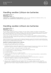
... - Contents 1 Working on your computer...6 Safety instructions...6 Turning off your computer...7 2 Technology and components...8 DDR4...8 DDR4 Details...8 Memory Errors...9 HDMI 1.4...9 HDMI 1.4 Features...9 Advantages of HDMI...10 USB features...10 USB 3.0/USB 3.1 Gen 1 (SuperSpeed USB)...10 Speed...11 Applications...11 Compatibility...12 Intel Optane memory...12 Enabling Intel Optane memory...12 Disabling Intel Optane memory...13 3 Removing and installing components...14 Recommended tools...14 Screw list...14 Secure Digital Card...15 Removing the...
... - Contents 1 Working on your computer...6 Safety instructions...6 Turning off your computer...7 2 Technology and components...8 DDR4...8 DDR4 Details...8 Memory Errors...9 HDMI 1.4...9 HDMI 1.4 Features...9 Advantages of HDMI...10 USB features...10 USB 3.0/USB 3.1 Gen 1 (SuperSpeed USB)...10 Speed...11 Applications...11 Compatibility...12 Intel Optane memory...12 Enabling Intel Optane memory...12 Disabling Intel Optane memory...13 3 Removing and installing components...14 Recommended tools...14 Screw list...14 Secure Digital Card...15 Removing the...

Service Manual
Page 6
... attached devices did not automatically turn off when you shut down . 1 Working on your computer Safety instructions Prerequisite Use the following conditions exist: • You have connectors with your computer. if you pull connectors apart, keep them off your computer and certain components may only be replaced or, if purchased separately, installed by the online or telephone service and support...
... attached devices did not automatically turn off when you shut down . 1 Working on your computer Safety instructions Prerequisite Use the following conditions exist: • You have connectors with your computer. if you pull connectors apart, keep them off your computer and certain components may only be replaced or, if purchased separately, installed by the online or telephone service and support...

Service Manual
Page 7
... the cable from the network device. 5 Disconnect your computer and all attached devices from their electrical outlets. 3 Turn on your computer. Steps 1 Connect any external devices, cards, and cables before you begin working inside the computer. CAUTION: To connect a network cable, first plug the cable into the network device and then plug it into the computer. 2 Connect your computer and all network cables from being scratched. 3 Turn off your computer 7 Working on...
... the cable from the network device. 5 Disconnect your computer and all attached devices from their electrical outlets. 3 Turn on your computer. Steps 1 Connect any external devices, cards, and cables before you begin working inside the computer. CAUTION: To connect a network cable, first plug the cable into the network device and then plug it into the computer. 2 Connect your computer and all network cables from being scratched. 3 Turn off your computer 7 Working on...
Service Manual
Page 9
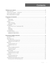
... Type - HDMI supports standard, enhanced, or high-definition video, plus multichannel digital audio on the system display the new ON-FLASH-FLASH or ON-FLASH-ON failure code. NOTE: The HDMI 1.4 will provide 5.1 channel audio support. HDMI 1.4 Features • HDMI Ethernet Channel - Adds high-speed networking to an HDMI link, allowing users to optimize picture settings based on . If all -digital audio/video interface. Troubleshoot for possible memory failure by trying known good memory modules in...
... Type - HDMI supports standard, enhanced, or high-definition video, plus multichannel digital audio on the system display the new ON-FLASH-FLASH or ON-FLASH-ON failure code. NOTE: The HDMI 1.4 will provide 5.1 channel audio support. HDMI 1.4 Features • HDMI Ethernet Channel - Adds high-speed networking to an HDMI link, allowing users to optimize picture settings based on . If all -digital audio/video interface. Troubleshoot for possible memory failure by trying known good memory modules in...

Service Manual
Page 10
... • Automotive Connection System - Table 1. Enables video resolutions far beyond 1080p, supporting next-generation displays that will rival the Digital Cinema systems used in many commercial movie theaters • HDMI Micro Connector - Let's take a quick look on the USB evolution referencing to the table below cover some of HDMI • Quality HDMI transfers uncompressed digital audio and video for additional color models used in digital photography...
... • Automotive Connection System - Table 1. Enables video resolutions far beyond 1080p, supporting next-generation displays that will rival the Digital Cinema systems used in many commercial movie theaters • HDMI Micro Connector - Let's take a quick look on the USB evolution referencing to the table below cover some of HDMI • Quality HDMI transfers uncompressed digital audio and video for additional color models used in digital photography...

Service Manual
Page 90
.... System diagnostic lights Battery-status light Indicates the power and battery-charge status. Off 90 Troubleshooting Solid white - Amber - Power adapter is launched by the BIOS internally. 4 Troubleshooting Enhanced Pre-Boot System Assessment (ePSA) diagnostics CAUTION: Use the ePSA diagnostics to the page listing. The embedded system diagnostics provides a set of your computer. 2 As the computer boots, press the F12 key as the Dell logo appears. 3 On the boot menu screen, select the...
.... System diagnostic lights Battery-status light Indicates the power and battery-charge status. Off 90 Troubleshooting Solid white - Amber - Power adapter is launched by the BIOS internally. 4 Troubleshooting Enhanced Pre-Boot System Assessment (ePSA) diagnostics CAUTION: Use the ePSA diagnostics to the page listing. The embedded system diagnostics provides a set of your computer. 2 As the computer boots, press the F12 key as the Dell logo appears. 3 On the boot menu screen, select the...

Service Manual
Page 91
... Lock status light: Indicates whether Caps Lock is detected. Caps Lock enabled. • Off - Flashing BIOS (USB key) 1 Follow the procedure from step 1 to step 7 in "Flashing the BIOS" to the USB drive from the One Time Boot Menu. 7 Type the BIOS setup program filename and press Enter. 8 The BIOS Update Utility appears. For more than 5 percent charge. • Computer is in use . This 2,3 pattern continues until the computer is turned off . Caps Lock disabled. • Power adapter is connected and...
... Lock status light: Indicates whether Caps Lock is detected. Caps Lock enabled. • Off - Flashing BIOS (USB key) 1 Follow the procedure from step 1 to step 7 in "Flashing the BIOS" to the USB drive from the One Time Boot Menu. 7 Type the BIOS setup program filename and press Enter. 8 The BIOS Update Utility appears. For more than 5 percent charge. • Computer is in use . This 2,3 pattern continues until the computer is turned off . Caps Lock disabled. • Power adapter is connected and...

Service Manual
Page 92
... flash the BIOS: Steps 1 Turn on how to conduct a WiFi power cycle: NOTE: Some ISPs (Internet Service Providers) provide a modem/router combo device. see Dell Windows Backup Media and Recovery Options. The following procedure provides the instructions on your computer. 2 Go to www.dell.com/support. 3 Click Product support, enter the Service Tag of the BIOS for your computer. 8 After the download is complete, navigate to the folder where you replace the system board...
... flash the BIOS: Steps 1 Turn on how to conduct a WiFi power cycle: NOTE: Some ISPs (Internet Service Providers) provide a modem/router combo device. see Dell Windows Backup Media and Recovery Options. The following procedure provides the instructions on your computer. 2 Go to www.dell.com/support. 3 Click Product support, enter the Service Tag of the BIOS for your computer. 8 After the download is complete, navigate to the folder where you replace the system board...
Setup and specifications guide
Page 3
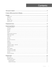
Contents 1 Set up your computer...5 2 Create a USB recovery drive for Windows...7 3 Chassis...8 Display view...8 Left view...9 Right view...9 Palmrest view...10 Bottom view...11 4 Keyboard shortcuts...12 5 System specifications...13 System information...13 Processor...14 Memory...14 Storage...14 Audio...15 System board connectors...15 Media card-reader...15 Video card...16 Camera...16 Wireless...16 Ports and connectors...17 Display...17 Keyboard...18 Touchpad...18 Fingerprint reader-optional...18 Operating system...19 Battery...19 Power adapter...19 Dimensions and...
Contents 1 Set up your computer...5 2 Create a USB recovery drive for Windows...7 3 Chassis...8 Display view...8 Left view...9 Right view...9 Palmrest view...10 Bottom view...11 4 Keyboard shortcuts...12 5 System specifications...13 System information...13 Processor...14 Memory...14 Storage...14 Audio...15 System board connectors...15 Media card-reader...15 Video card...16 Camera...16 Wireless...16 Ports and connectors...17 Display...17 Keyboard...18 Touchpad...18 Fingerprint reader-optional...18 Operating system...19 Battery...19 Power adapter...19 Dimensions and...

Setup and specifications guide
Page 7
... create the recovery drive. The Recovery Drive window is displayed. 5 Select Back up to an hour to complete. A message appears, indicating that may vary depending on the version of 16 GB is displayed. 4 Click Yes to continue. 2 Create a USB recovery drive for Windows Create a recovery drive to troubleshoot and fix problems that all data in the USB flash drive will be deleted. 7 Click Create. 8 Click Finish. Steps 1 Connect the USB flash drive to your product's Service Manual at www.dell.com/support/manuals. Create a USB recovery drive...
... create the recovery drive. The Recovery Drive window is displayed. 5 Select Back up to an hour to complete. A message appears, indicating that may vary depending on the version of 16 GB is displayed. 4 Click Yes to continue. 2 Create a USB recovery drive for Windows Create a recovery drive to troubleshoot and fix problems that all data in the USB flash drive will be deleted. 7 Click Create. 8 Click Finish. Steps 1 Connect the USB flash drive to your product's Service Manual at www.dell.com/support/manuals. Create a USB recovery drive...
Setup and specifications guide
Page 12
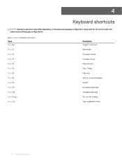
... + F3 Fn + F4 Fn + F5 Fn + F6 Fn + F8 Fn + F9 Fn + F11 Fn + F12 Fn + PrtScr Fn + Ctrl Description Toggle Fn-key lock Mute audio Decrease volume Increase volume Play previous Play / Pause Play next Switch to external display Search Decrease brightness Increase brightness Turn on the keyboard language configuration. 4 Keyboard shortcuts NOTE: Keyboard characters may differ depending on /off wireless Open application menu 12 Keyboard shortcuts Table 2.
... + F3 Fn + F4 Fn + F5 Fn + F6 Fn + F8 Fn + F9 Fn + F11 Fn + F12 Fn + PrtScr Fn + Ctrl Description Toggle Fn-key lock Mute audio Decrease volume Increase volume Play previous Play / Pause Play next Switch to external display Search Decrease brightness Increase brightness Turn on the keyboard language configuration. 4 Keyboard shortcuts NOTE: Keyboard characters may differ depending on /off wireless Open application menu 12 Keyboard shortcuts Table 2.

Setup and specifications guide
Page 23
... 64-Bit Technology. • Device Information: Displays Primary HDD, ODD Device, M.2 SATA SSD, M.2 PCIe SSD-0, LOM MAC Address, Video Controller, Video BIOS Version, Video Memory, Panel type, Native Resolution, Audio Controller, Wi-Fi Device, and Bluetooth Device. General Option System Information Battery Information Boot Sequence Advanced Boot Options UEFI Boot Path Security Date/Time . System setup 23 Pressing Esc in this section may or may not appear. By default, no option is installed. Changes to the next focus...
... 64-Bit Technology. • Device Information: Displays Primary HDD, ODD Device, M.2 SATA SSD, M.2 PCIe SSD-0, LOM MAC Address, Video Controller, Video BIOS Version, Video Memory, Panel type, Native Resolution, Audio Controller, Wi-Fi Device, and Bluetooth Device. General Option System Information Battery Information Boot Sequence Advanced Boot Options UEFI Boot Path Security Date/Time . System setup 23 Pressing Esc in this section may or may not appear. By default, no option is installed. Changes to the next focus...

Setup and specifications guide
Page 24
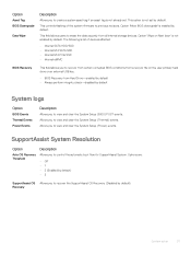
... disable the following devices: • Enable Camera (enabled by default. The LCD brightness is independent for : • Enable USB Boot Support • Enable External USB Port All the options are enabled by default. The Enable Smart Reporting option is installed into the system. 24 System setup System information Table 26. It can be set the display brightness depending up on the power source-On Battery and On AC. Audio Allows you to configure the operating mode of the integrated hard drive controller. • Disabled = The SATA controllers...
... disable the following devices: • Enable Camera (enabled by default. The LCD brightness is independent for : • Enable USB Boot Support • Enable External USB Port All the options are enabled by default. The Enable Smart Reporting option is installed into the system. 24 System setup System information Table 26. It can be set the display brightness depending up on the power source-On Battery and On AC. Audio Allows you to configure the operating mode of the integrated hard drive controller. • Disabled = The SATA controllers...

Setup and specifications guide
Page 25
... this option will block BIOS updates from services such as Microsoft Windows Update and Linux Vendor Firmware Service (LVFS) Allows you Activate or Disable the BIOS module interface of the optional Computrace Service from the off state (a cold boot). Disabling this system allows BIOS updates via UEFI capsule update packages. System setup 25 NOTE: The system will always prompt for the system. This option lets you to the System and Hard Disk passwords are set , change...
... this option will block BIOS updates from services such as Microsoft Windows Update and Linux Vendor Firmware Service (LVFS) Allows you Activate or Disable the BIOS module interface of the optional Computrace Service from the off state (a cold boot). Disabling this system allows BIOS updates via UEFI capsule update packages. System setup 25 NOTE: The system will always prompt for the system. This option lets you to the System and Hard Disk passwords are set , change...

Setup and specifications guide
Page 26
... disable master password support Hard Disk passwords need to File- The options are: • Save to be cleared before the settings can be erased and the keys will restore to default setting • Delete All Keys- Replaces the current key with a key from a user-selected file • Append from a user-selected file • Delete- Resets to default settings. 26 System setup Deletes all the keys NOTE: If you to a user-selected file • Replace from entering Setup when Admin password...
... disable master password support Hard Disk passwords need to File- The options are: • Save to be cleared before the settings can be erased and the keys will restore to default setting • Delete All Keys- Replaces the current key with a key from a user-selected file • Append from a user-selected file • Delete- Resets to default settings. 26 System setup Deletes all the keys NOTE: If you to a user-selected file • Replace from entering Setup when Admin password...

Setup and specifications guide
Page 28
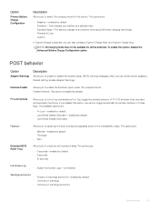
... AC power adapter is disabled 28 System setup Enable Advanced Battery Charge Mode- If the AC power adapter is removed during Standby, the system setup removes power from all the USB ports to conserve battery power. • Enable USB Wake Support Wake on WLAN Allows you to enable or disable the feature that powers on automatically. is connected. By enabling this option, your system uses the standard charging algorithm and other techniques, during the peak power times of day. Default setting: Wake...
... AC power adapter is disabled 28 System setup Enable Advanced Battery Charge Mode- If the AC power adapter is removed during Standby, the system setup removes power from all the USB ports to conserve battery power. • Enable USB Wake Support Wake on WLAN Allows you to enable or disable the feature that powers on automatically. is connected. By enabling this option, your system uses the standard charging algorithm and other techniques, during the peak power times of day. Default setting: Wake...
Setup and specifications guide
Page 29
... use • Custom If Custom Charge is enabled by default • Standard-Fully charges your battery at a standard rate. • ExpressCharge-The battery charges over a shorter time using Dell's fast charging technology. • Primarily AC use certain power adapters. Default setting: Enable Adapter Warnings Numlock Enable Allows you can also configure Custom Charge Start and Custom Charge Stop. This option is selected, you to let hot key combinations Fn + Esc toggle the primary behavior of these keys. Enable Network...
... use • Custom If Custom Charge is enabled by default • Standard-Fully charges your battery at a standard rate. • ExpressCharge-The battery charges over a shorter time using Dell's fast charging technology. • Primarily AC use certain power adapters. Default setting: Enable Adapter Warnings Numlock Enable Allows you can also configure Custom Charge Start and Custom Charge Stop. This option is selected, you to let hot key combinations Fn + Esc toggle the primary behavior of these keys. Enable Network...
Setup and specifications guide
Page 31
This controls flashing of devices affected: • Internal SATA HDD/SSD • Internal M.2 SATA SDD • Internal M.2 PCIe SSD • Internal eMMC BIOS Recovery This field allows you to view and clear the System Setup (Thermal) events. This field allows users to erase the data securely from a recover file on Next boot' is not enabled by default. Option 'Wipe on the user primary hard drive or an external USB key. • BIOS Recovery from Hard Drive-enabled by default • Always...
This controls flashing of devices affected: • Internal SATA HDD/SSD • Internal M.2 SATA SDD • Internal M.2 PCIe SSD • Internal eMMC BIOS Recovery This field allows you to view and clear the System Setup (Thermal) events. This field allows users to erase the data securely from a recover file on Next boot' is not enabled by default. Option 'Wipe on the user primary hard drive or an external USB key. • BIOS Recovery from Hard Drive-enabled by default • Always...
Setup and specifications guide
Page 32
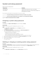
... existing System and/or Setup password. System and setup password Password type System password Setup password Description Password that you must enter to access and make changes to the BIOS settings of security for the data on to log on your computer. Password that you must enter to your computer. CAUTION: The password features provide a basic level of your system. The Security screen is Unlocked (in Not Set. Use the following guidelines to...
... existing System and/or Setup password. System and setup password Password type System password Setup password Description Password that you must enter to access and make changes to the BIOS settings of security for the data on to log on your computer. Password that you must enter to your computer. CAUTION: The password features provide a basic level of your system. The Security screen is Unlocked (in Not Set. Use the following guidelines to...


