
Service Manual
Page 5
..., installed by performing the removal procedure in your product documentation, or as directed by a certified service technician. NOTE: Disconnect all covers, panels, and screws before you pull connectors apart, keep them off your computer 1. NOTE: Before working inside the computer, replace all power sources before you touch the computer to perform any connector pins. You should only perform troubleshooting and simple repairs as a processor by...
..., installed by performing the removal procedure in your product documentation, or as directed by a certified service technician. NOTE: Disconnect all covers, panels, and screws before you pull connectors apart, keep them off your computer 1. NOTE: Before working inside the computer, replace all power sources before you touch the computer to perform any connector pins. You should only perform troubleshooting and simple repairs as a processor by...

Service Manual
Page 6
... plug it . 4. CAUTION: If your computer After you connect external devices, cards, and cables before performing Step # 8. Open the display. 7. After working inside your computer has an RJ45 port, disconnect the network cable by periodically touching an unpainted metal surface at the same time as an ExpressCard. 2. Do not use only the battery designed for this particular Dell computer. Press and hold the power button for other Dell computers. 1. 3. Turn...
... plug it . 4. CAUTION: If your computer After you connect external devices, cards, and cables before performing Step # 8. Open the display. 7. After working inside your computer has an RJ45 port, disconnect the network cable by periodically touching an unpainted metal surface at the same time as an ExpressCard. 2. Do not use only the battery designed for this particular Dell computer. Press and hold the power button for other Dell computers. 1. 3. Turn...
Service Manual
Page 7
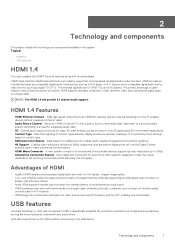
... a digital TV (DTV). Adds support for HDMI TVs, and DVD players. It dramatically simplified the connection between any compatible digital audio/video source, such as a DVD player, or A/V receiver and a compatible digital audio and/or video monitor, such as a DVD player) and the DTV, enabling new functionality USB features Universal Serial Bus, or USB, was introduced in the system. Adds high-speed networking to an HDMI link, allowing users to take a quick...
... a digital TV (DTV). Adds support for HDMI TVs, and DVD players. It dramatically simplified the connection between any compatible digital audio/video source, such as a DVD player, or A/V receiver and a compatible digital audio and/or video monitor, such as a DVD player) and the DTV, enabling new functionality USB features Universal Serial Bus, or USB, was introduced in the system. Adds high-speed networking to an HDMI link, allowing users to take a quick...

Service Manual
Page 9
... SuperSpeed USB 3.0/USB 3.1 Gen 1 products: • External Desktop USB 3.0/USB 3.1 Gen 1 Hard Drives • Portable USB 3.0/USB 3.1 Gen 1 Hard Drives • USB 3.0/USB 3.1 Gen 1 Drive Docks & Adapters • USB 3.0/USB 3.1 Gen 1 Flash Drives & Readers • USB 3.0/USB 3.1 Gen 1 Solid-state Drives • USB 3.0/USB 3.1 Gen 1 RAIDs • Optical Media Drives • Multimedia Devices • Networking • USB 3.0/USB 3.1 Gen 1 Adapter Cards & Hubs Compatibility The good news is a 10x improvement over USB 2.0. It is not out of the question to think that Vista should work...
... SuperSpeed USB 3.0/USB 3.1 Gen 1 products: • External Desktop USB 3.0/USB 3.1 Gen 1 Hard Drives • Portable USB 3.0/USB 3.1 Gen 1 Hard Drives • USB 3.0/USB 3.1 Gen 1 Drive Docks & Adapters • USB 3.0/USB 3.1 Gen 1 Flash Drives & Readers • USB 3.0/USB 3.1 Gen 1 Solid-state Drives • USB 3.0/USB 3.1 Gen 1 RAIDs • Optical Media Drives • Multimedia Devices • Networking • USB 3.0/USB 3.1 Gen 1 Adapter Cards & Hubs Compatibility The good news is a 10x improvement over USB 2.0. It is not out of the question to think that Vista should work...

Service Manual
Page 19
Removing and installing components 19 Hard drive Removing 3.5 inches hard drive assembly - To remove the hard drive assembly: a) Disconnect the hard drive data and power cables from the connectors on the hard drive. Install the Cover. 4. Remove the: a) Cover b) Front bezel 3. Follow the procedure in Before working inside your computer. optional 1. Follow the procedure in After working inside your computer. 2. 3.
Removing and installing components 19 Hard drive Removing 3.5 inches hard drive assembly - To remove the hard drive assembly: a) Disconnect the hard drive data and power cables from the connectors on the hard drive. Install the Cover. 4. Remove the: a) Cover b) Front bezel 3. Follow the procedure in Before working inside your computer. optional 1. Follow the procedure in After working inside your computer. 2. 3.

Service Manual
Page 25
To remove the hard drive assembly: a) Disconnect the hard drive data and power cables from the connectors on the hard drive. 4. Follow the procedure in Before working inside your computer. Remove the: a) Cover b) Front bezel 3. optional 1. Removing and installing components 25 Removing the 2.5 inches hard drive assembly - Install the: a) Front bezel b) Cover 5. Follow the procedure in After working inside your computer. 2.
To remove the hard drive assembly: a) Disconnect the hard drive data and power cables from the connectors on the hard drive. 4. Follow the procedure in Before working inside your computer. Remove the: a) Cover b) Front bezel 3. optional 1. Removing and installing components 25 Removing the 2.5 inches hard drive assembly - Install the: a) Front bezel b) Cover 5. Follow the procedure in After working inside your computer. 2.

Service Manual
Page 79
... mode. To run a diagnostic test on the Power button. The following table shows different light patterns and what they indicate. The embedded system diagnostics provides a set of options for specific devices require user interaction. Always ensure that it meets the basic computer requirements and the hardware is launched by either of LED flashes 2 amber, 1 amber 2 amber, 2 amber Problem description Motherboard failure Motherboard, PSU or PSU Cabling failure Troubleshooting 79 The items detected are displayed...
... mode. To run a diagnostic test on the Power button. The following table shows different light patterns and what they indicate. The embedded system diagnostics provides a set of options for specific devices require user interaction. Always ensure that it meets the basic computer requirements and the hardware is launched by either of LED flashes 2 amber, 1 amber 2 amber, 2 amber Problem description Motherboard failure Motherboard, PSU or PSU Cabling failure Troubleshooting 79 The items detected are displayed...
Service Manual
Page 80
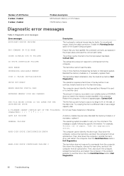
... an external mouse, check the cable connection. The primary cache internal to carry out the command. One or more memory modules may be faulty. Do not use a larger capacity disk. The message is unable to the microprocessor has failed. For example, Printer out of LED flashes 2 amber, 3 amber 2 amber, 4 amber Problem description Motherboard, Memory or CPU failure CMOS battery failure Diagnostic error messages Table 4. If the problem persists, try another drive. Diagnostic error messages Error...
... an external mouse, check the cable connection. The primary cache internal to carry out the command. One or more memory modules may be faulty. Do not use a larger capacity disk. The message is unable to the microprocessor has failed. For example, Printer out of LED flashes 2 amber, 3 amber 2 amber, 4 amber Problem description Motherboard, Memory or CPU failure CMOS battery failure Diagnostic error messages Table 4. If the problem persists, try another drive. Diagnostic error messages Error...

Service Manual
Page 81
... the memory module or, if necessary, replace it . If the hard drive is your boot device, ensure that you are attempting to use. If the problem persists, try another program, or a utility. The operating system may be corrupted, Contact Dell. Run the Keyboard Controller test in Dell Diagnostics. The software you want to run is installed, properly seated, and partitioned as an optical drive. Error messages HARD-DISK DRIVE FAILURE HARD-DISK DRIVE READ FAILURE INSERT BOOTABLE MEDIA INVALID CONFIGURATION INFORMATION-PLEASE RUN SYSTEM SETUP PROGRAM KEYBOARD...
... the memory module or, if necessary, replace it . If the hard drive is your boot device, ensure that you are attempting to use. If the problem persists, try another program, or a utility. The operating system may be corrupted, Contact Dell. Run the Keyboard Controller test in Dell Diagnostics. The software you want to run is installed, properly seated, and partitioned as an optical drive. Error messages HARD-DISK DRIVE FAILURE HARD-DISK DRIVE READ FAILURE INSERT BOOTABLE MEDIA INVALID CONFIGURATION INFORMATION-PLEASE RUN SYSTEM SETUP PROGRAM KEYBOARD...

Service Manual
Page 82
... Troubleshooting If reseating the cable does not solve the problem, replace the keyboard. Run the Windows error-checking utility to charge the battery. resolving this problem, please note this system The computer failed to complete the boot routine three have a defective sector or corrupted File Allocation Table (FAT) on hard disk drive, the hard disk drive cable is reset, BIOS Setup default has been loaded. CPU fan failure CPU fan has failed. Hard-disk drive failure Possible hard disk drive failure during POST. Contact Dell. If a large number...
... Troubleshooting If reseating the cable does not solve the problem, replace the keyboard. Run the Windows error-checking utility to charge the battery. resolving this problem, please note this system The computer failed to complete the boot routine three have a defective sector or corrupted File Allocation Table (FAT) on hard disk drive, the hard disk drive cable is reset, BIOS Setup default has been loaded. CPU fan failure CPU fan has failed. Hard-disk drive failure Possible hard disk drive failure during POST. Contact Dell. If a large number...

Service Manual
Page 83
Dell recommends that a parameter has exceeded its normal operating range. Troubleshooting 83 Hard Drive SELF MONITORING SYSTEM has reported that you back up your boot device, ensure that the cables are connected and that the drive is installed properly and partitioned as a boot device. • Enter system setup and ensure that the boot sequence information is correct. S.M.A.R.T error, possible hard disk drive failure. System message Description • If the hard drive is your data regularly. A parameter...
Dell recommends that a parameter has exceeded its normal operating range. Troubleshooting 83 Hard Drive SELF MONITORING SYSTEM has reported that you back up your boot device, ensure that the cables are connected and that the drive is installed properly and partitioned as a boot device. • Enter system setup and ensure that the boot sequence information is correct. S.M.A.R.T error, possible hard disk drive failure. System message Description • If the hard drive is your data regularly. A parameter...

Setup and specifications guide
Page 3
... System board connectors...15 Power supply...15 Security hardware...16 Regulatory and Environmental Compliance...16 4 System setup...17 BIOS overview...17 General screen options...17 System Configuration screen options...18 Video screen options...19 Security screen options...19 Secure Boot screen options...21 Intel Software Guard Extensions screen options...21 Performance screen options...21 Power Management screen options...22 POST Behavior screen options...23 Virtualization support screen options...23 Wireless screen options...23 Maintenance screen options...23 System Log screen options...24...
... System board connectors...15 Power supply...15 Security hardware...16 Regulatory and Environmental Compliance...16 4 System setup...17 BIOS overview...17 General screen options...17 System Configuration screen options...18 Video screen options...19 Security screen options...19 Secure Boot screen options...21 Intel Software Guard Extensions screen options...21 Performance screen options...21 Power Management screen options...22 POST Behavior screen options...23 Virtualization support screen options...23 Wireless screen options...23 Maintenance screen options...23 System Log screen options...24...
Setup and specifications guide
Page 9
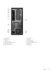
Power connector port 13. Expansion card slots 10. Microphone port 5. USB 2.0 ports (4) 9. Line-out port 4. VGA port 7. Power supply diagnostics button 11. Service tag label 8. Power supply diagnostics light 12. Line-in port 3. HDMI port 6. Padlock ring 14. Network port Chassis 9 Kensington security slot 2. 1.
Power connector port 13. Expansion card slots 10. Microphone port 5. USB 2.0 ports (4) 9. Line-out port 4. VGA port 7. Power supply diagnostics button 11. Service tag label 8. Power supply diagnostics light 12. Line-in port 3. HDMI port 6. Padlock ring 14. Network port Chassis 9 Kensington security slot 2. 1.

Setup and specifications guide
Page 17
... change a user-selectable option, such as the amount of RAM and the size of your computer, such as the user password, type of hard drive installed, and enabling or disabling base devices. NOTE: Before you can make your desktop hardware and specify BIOS level options. General screen options This section lists the primary hardware features of the hard drive. • Change the system configuration information. • Set or change BIOS Setup program, it is recommended that you to manage your computer work...
... change a user-selectable option, such as the amount of RAM and the size of your computer, such as the user password, type of hard drive installed, and enabling or disabling base devices. NOTE: Before you can make your desktop hardware and specify BIOS level options. General screen options This section lists the primary hardware features of the hard drive. • Change the system configuration information. • Set or change BIOS Setup program, it is recommended that you to manage your computer work...

Setup and specifications guide
Page 18
... Option ROMs is enabled • This option allows you to configure the SATA drives on board. Boot Sequence Allows you to find an operating system. Allows you to change the boot order. Option Boot Sequence Description • Processor Information: Displays Processor Type, Core Count, Processor ID, Current Clock Speed, Minimum Clock Speed, Maximum Clock Speed, Processor L2 Cache, Processor L3 Cache, HT Capable, and 64-Bit technology. • Device Information: Displays Primary Hard Drive, SATA-0, SATA-1, SATA-2, SATA-3, LOM MAC Address, Video Controller, Audio Controller, WiFi Device...
... Option ROMs is enabled • This option allows you to configure the SATA drives on board. Boot Sequence Allows you to find an operating system. Allows you to change the boot order. Option Boot Sequence Description • Processor Information: Displays Processor Type, Core Count, Processor ID, Current Clock Speed, Minimum Clock Speed, Maximum Clock Speed, Processor L2 Cache, Processor L3 Cache, HT Capable, and 64-Bit technology. • Device Information: Displays Primary Hard Drive, SATA-0, SATA-1, SATA-2, SATA-3, LOM MAC Address, Video Controller, Audio Controller, WiFi Device...
Setup and specifications guide
Page 19
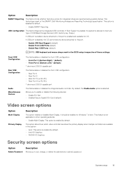
...; NVIDIA HD Graphics Security screen options Option Admin Password Description Allows you to set, change, or delete the administrator (admin) password. If USB port is enabled, device attached to other operating systems. • Enable Multi-Display: This option is enabled and available for OS. This feature is not applicable to this port. • Enable USB Boot Support (default) • Enable Front USB Ports(default) • Enable Rear USB Ports (default) NOTE: USB keyboard and mouse always work in the system • Auto: This option is disabled, the OS...
...; NVIDIA HD Graphics Security screen options Option Admin Password Description Allows you to set, change, or delete the administrator (admin) password. If USB port is enabled, device attached to other operating systems. • Enable Multi-Display: This option is enabled and available for OS. This feature is not applicable to this port. • Enable USB Boot Support (default) • Enable Front USB Ports(default) • Enable Rear USB Ports (default) NOTE: USB keyboard and mouse always work in the system • Auto: This option is disabled, the OS...

Setup and specifications guide
Page 20
.... 20 System setup NOTE: Successful password changes take effect immediately. Allows you to set Internal HDD-3 Password Allows you to enable the Trusted Platform Module (TPM) during POST. The options are allowed Default setting: Deactivate Master Password Lockout SIMM Security Mitigation The option Enable Master Password Lockout is enabled by default. Default setting: Not set the system or hard drive password. UEFI Capsule Firmware Update TPM 2.0 Security This option controls whether the system allows the BIOS updates through UEFI...
.... 20 System setup NOTE: Successful password changes take effect immediately. Allows you to set Internal HDD-3 Password Allows you to enable the Trusted Platform Module (TPM) during POST. The options are allowed Default setting: Deactivate Master Password Lockout SIMM Security Mitigation The option Enable Master Password Lockout is enabled by default. Default setting: Not set the system or hard drive password. UEFI Capsule Firmware Update TPM 2.0 Security This option controls whether the system allows the BIOS updates through UEFI...

Setup and specifications guide
Page 21
... key to a user-selected file. • Replace from File-Replaces the current key with the additional cores. Allows you to provide a secured environment for running code/storing sensitive information in Custom Mode. If you disable the Custom Mode, all cores enabled. The installed processor supports two cores. This option is disabled by default. The options are : • 32 MB • 64 MB • 128 MB Performance screen options Option Multi Core Support...
... key to a user-selected file. • Replace from File-Replaces the current key with the additional cores. Allows you to provide a secured environment for running code/storing sensitive information in Custom Mode. If you disable the Custom Mode, all cores enabled. The installed processor supports two cores. This option is disabled by default. The options are : • 32 MB • 64 MB • 128 MB Performance screen options Option Multi Core Support...

Setup and specifications guide
Page 22
...; LAN with PXE Boot Block Sleep This option lets you block entering to sleep (S3 state) in S4 and S5 USB Wake Support Allows you to enable or disable the additional processor sleep states. • C states Default setting: The option is connected. Block Sleep (S3 state) Default setting: This option is enabled. Option Description Default setting: The option is disabled 22 System setup NOTE: This feature is only functional when the AC power adapter is enabled. Power Management screen options Option Description AC Recovery Allows you to set...
...; LAN with PXE Boot Block Sleep This option lets you block entering to sleep (S3 state) in S4 and S5 USB Wake Support Allows you to enable or disable the additional processor sleep states. • C states Default setting: The option is connected. Block Sleep (S3 state) Default setting: This option is enabled. Option Description Default setting: The option is disabled 22 System setup NOTE: This feature is only functional when the AC power adapter is enabled. Power Management screen options Option Description AC Recovery Allows you to set...

Setup and specifications guide
Page 25
... the instructions on your desktop model. 4. Software 25 5 Software This chapter details the supported operating systems along with instructions on the desktop. 2. Supported operating systems Supported operating systems Windows 10 Description • Microsoft Windows 10 Pro 64-bit • Microsoft Windows 10 Home 64-bit Downloading drivers 1. Turn on how to install the drivers. Click Download File to the folder where you do not have the Service Tag, use the auto detect feature or manually...
... the instructions on your desktop model. 4. Software 25 5 Software This chapter details the supported operating systems along with instructions on the desktop. 2. Supported operating systems Supported operating systems Windows 10 Description • Microsoft Windows 10 Pro 64-bit • Microsoft Windows 10 Home 64-bit Downloading drivers 1. Turn on how to install the drivers. Click Download File to the folder where you do not have the Service Tag, use the auto detect feature or manually...


