Service Manual
Page 10
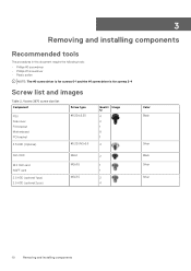
...; Plastic scribe NOTE: The #0 screw driver is for screws 0-1 and the #1 screw driver is for screws 2-4 Screw list and images Table 2. Vostro 3670 screw size list Component PSU Side cover FIO bracket Motherboard PCI bracket 3.5 HDD (Optional) Screw type #6.32xL6.35 #6.32UNCx3.6 Quanti Image ty 4 2 1 8 1 4 Color Black Silver Slim ODD M.2 SSD card NGFF...
...; Plastic scribe NOTE: The #0 screw driver is for screws 0-1 and the #1 screw driver is for screws 2-4 Screw list and images Table 2. Vostro 3670 screw size list Component PSU Side cover FIO bracket Motherboard PCI bracket 3.5 HDD (Optional) Screw type #6.32xL6.35 #6.32UNCx3.6 Quanti Image ty 4 2 1 8 1 4 Color Black Silver Slim ODD M.2 SSD card NGFF...

Service Manual
Page 67
Press the release lever down and then move it inward to seat the processor. Removing and installing components 67 Installing the processor 1. NOTE: Align pin 1 on the motherboard CAUTION: Do not use force to secure it engages easily into the socket. 2. Insert the processor in the processor socket. Ensure the processor is positioned correctly, it with pin 1 on the cpu with the retention hook. When the processor is properly seated. Lower the processor cover. 3.
Press the release lever down and then move it inward to seat the processor. Removing and installing components 67 Installing the processor 1. NOTE: Align pin 1 on the motherboard CAUTION: Do not use force to secure it engages easily into the socket. 2. Insert the processor in the processor socket. Ensure the processor is positioned correctly, it with pin 1 on the cpu with the retention hook. When the processor is properly seated. Lower the processor cover. 3.

Service Manual
Page 79
...arrow in a normal mode. Table 3. Always ensure that you of your computer. Note the error code and validation number and contact Dell. Repeat Step 4 and Step 8 Diagnostics The computer POST (Power On Self Test) ensures that inform you are present at the ...the diagnostic test. 7. The embedded system diagnostics provides a set of LED flashes 2 amber, 1 amber 2 amber, 2 amber Problem description Motherboard failure Motherboard, PSU or PSU Cabling failure Troubleshooting 79 To run a diagnostic test on screen and launch ePSA/diagnostics directly. 3. Select the device from ...
...arrow in a normal mode. Table 3. Always ensure that you of your computer. Note the error code and validation number and contact Dell. Repeat Step 4 and Step 8 Diagnostics The computer POST (Power On Self Test) ensures that inform you are present at the ...the diagnostic test. 7. The embedded system diagnostics provides a set of LED flashes 2 amber, 1 amber 2 amber, 2 amber Problem description Motherboard failure Motherboard, PSU or PSU Cabling failure Troubleshooting 79 To run a diagnostic test on screen and launch ePSA/diagnostics directly. 3. Select the device from ...
Service Manual
Page 80
.... Restart the computer. The computer cannot identify the ExpressCard. Run the hard drive tests in Dell Diagnostics. 80 Troubleshooting Run the Hard Disk Drive tests in Dell Diagnostics. Number of LED flashes 2 amber, 3 amber 2 amber, 4 amber Problem description Motherboard, Memory or CPU failure CMOS battery failure Diagnostic error messages Table 4. The hard drive...
.... Restart the computer. The computer cannot identify the ExpressCard. Run the hard drive tests in Dell Diagnostics. 80 Troubleshooting Run the Hard Disk Drive tests in Dell Diagnostics. Number of LED flashes 2 amber, 3 amber 2 amber, 4 amber Problem description Motherboard, Memory or CPU failure CMOS battery failure Diagnostic error messages Table 4. The hard drive...

Service Manual
Page 83
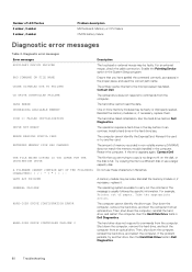
... may or may not indicate a potential hard drive problem A chip on the system board might be malfunctioning or motherboard failure. No timer tick interrupt NOTICE - S.M.A.R.T error, possible hard disk drive failure. Troubleshooting 83 Dell recommends that a parameter has exceeded its normal operating range. Hard Drive SELF MONITORING SYSTEM has reported that you...
... may or may not indicate a potential hard drive problem A chip on the system board might be malfunctioning or motherboard failure. No timer tick interrupt NOTICE - S.M.A.R.T error, possible hard disk drive failure. Troubleshooting 83 Dell recommends that a parameter has exceeded its normal operating range. Hard Drive SELF MONITORING SYSTEM has reported that you...


