
Ownerss Manual
Page 4
... Removing display hinge...37 Installing display hinge...37 DC-in...38 Removing the DC-in...38 Installing the DC-in...38 Keyboard lattice and Keyboard...39 Removing the keyboard...39 Installing the keyboard...40 Palm rest...41 Removing and installing palmrest...41 eDP cable...42 Removing the eDP cable...42 Installing the eDP cable...
... Removing display hinge...37 Installing display hinge...37 DC-in...38 Removing the DC-in...38 Installing the DC-in...38 Keyboard lattice and Keyboard...39 Removing the keyboard...39 Installing the keyboard...40 Palm rest...41 Removing and installing palmrest...41 eDP cable...42 Removing the eDP cable...42 Installing the eDP cable...

Ownerss Manual
Page 5
Communication specification...51 Ports and connectors specification...51 Display specification...51 Keyboard...52 Touchpad specification...52 Camera...52 Storage specification...52 Battery specification...52 AC adapter...53 Physical specification...53 Environmental specification...54 5 System setup...55... the BIOS in Windows ...65 Updating BIOS on systems with BitLocker enabled 66 Updating your system BIOS using a USB flash drive 66 Updating the Dell BIOS in Linux and Ubuntu environments 67 Flashing the BIOS from the F12 One-Time boot menu 67 System and setup password...70 Assigning a system...
Communication specification...51 Ports and connectors specification...51 Display specification...51 Keyboard...52 Touchpad specification...52 Camera...52 Storage specification...52 Battery specification...52 AC adapter...53 Physical specification...53 Environmental specification...54 5 System setup...55... the BIOS in Windows ...65 Updating BIOS on systems with BitLocker enabled 66 Updating your system BIOS using a USB flash drive 66 Updating the Dell BIOS in Linux and Ubuntu environments 67 Flashing the BIOS from the F12 One-Time boot menu 67 System and setup password...70 Assigning a system...

Ownerss Manual
Page 27
d) Lift the USB Type C port bracket away from the connector. 3. To remove the system board: a) Disconnect the following cables: • Input output(I/O) board cable [1,2] • Input output(I/O) board cable [3] • Keyboard backlight cable [4] • Keyboard and Touchpad cable [5] b) Disconnect the eDP cable [1], power adapter port cable [2] and speaker cable [5] from the system [4]. Removing and installing components 27 c) Remove the two M2.0 x 4 screws that secure the USB Type C port bracket to the system board [3].
d) Lift the USB Type C port bracket away from the connector. 3. To remove the system board: a) Disconnect the following cables: • Input output(I/O) board cable [1,2] • Input output(I/O) board cable [3] • Keyboard backlight cable [4] • Keyboard and Touchpad cable [5] b) Disconnect the eDP cable [1], power adapter port cable [2] and speaker cable [5] from the system [4]. Removing and installing components 27 c) Remove the two M2.0 x 4 screws that secure the USB Type C port bracket to the system board [3].

Ownerss Manual
Page 29
... board 1. Align the screw holes on the system board with the screw holes on the system. 2. Connect the Input output board cable, speaker cable, keyboard backlight cable, keyboard cable and touchpad cable to the system and lift the touchpad away from the connector in Before working inside your computer. Touchpad Removing touchpad...
... board 1. Align the screw holes on the system board with the screw holes on the system. 2. Connect the Input output board cable, speaker cable, keyboard backlight cable, keyboard cable and touchpad cable to the system and lift the touchpad away from the connector in Before working inside your computer. Touchpad Removing touchpad...

Ownerss Manual
Page 39
... e) solid state drive(SSD) f) WLAN card g) Input output(I/O) board h) power button i) hard drive j) system board k) display assembly 3. c) Lift the keyboard bracket away from the connector in Before working inside your computer. b) Disconnect the keyboard cable from the system. Follow the procedure in After working inside your computer. 2. Removing and installing components 39...
... e) solid state drive(SSD) f) WLAN card g) Input output(I/O) board h) power button i) hard drive j) system board k) display assembly 3. c) Lift the keyboard bracket away from the connector in Before working inside your computer. b) Disconnect the keyboard cable from the system. Follow the procedure in After working inside your computer. 2. Removing and installing components 39...

Ownerss Manual
Page 40
Install the: a) display assembly 40 Removing and installing components Replace the screws that secures the keyboard to the slot on the palm rest. 3. Place the keyboard bracket above the keyboard in to the system. 5. Installing the keyboard 1. d) Remove the four screws that secure the keyboard on the palm rest. 2. Place the keyboard on to the palmrest [1] e) Lift the keyboard away from the system [2]. Replace the screws to secure the keyboard to the system slot. 4.
Install the: a) display assembly 40 Removing and installing components Replace the screws that secures the keyboard to the slot on the palm rest. 3. Place the keyboard bracket above the keyboard in to the system. 5. Installing the keyboard 1. d) Remove the four screws that secure the keyboard on the palm rest. 2. Place the keyboard on to the palmrest [1] e) Lift the keyboard away from the system [2]. Replace the screws to secure the keyboard to the system slot. 4.

Ownerss Manual
Page 41
... palmrest 1. Follow the procedure in After working inside your computer. 2. b) system board c) hard drive d) powered button e) Input Output(I /O) board j) power button k) hard drive l) system board m) keyboard n) display assembly NOTE: After the removal of all the components the component that you are left with is the palm rest Removing and installing components...
... palmrest 1. Follow the procedure in After working inside your computer. 2. b) system board c) hard drive d) powered button e) Input Output(I /O) board j) power button k) hard drive l) system board m) keyboard n) display assembly NOTE: After the removal of all the components the component that you are left with is the palm rest Removing and installing components...

Ownerss Manual
Page 42
... from the routing channel to remove from the display. 42 Removing and installing components Install the following components on the new palm rest: a) display assembly b) keyboard c) system board d) hard drive e) powered button f) Input Output(I/O) board g) WLAN card h) solid state drive(SSD) i) heat sink j) system fan k) touchpad l) speaker m) battery n) base cover 4. eDP...
... from the routing channel to remove from the display. 42 Removing and installing components Install the following components on the new palm rest: a) display assembly b) keyboard c) system board d) hard drive e) powered button f) Input Output(I/O) board g) WLAN card h) solid state drive(SSD) i) heat sink j) system fan k) touchpad l) speaker m) battery n) base cover 4. eDP...
Ownerss Manual
Page 46
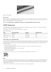
... a theoretically 10 times faster than its predecessor. It dramatically simplified the connection between host computers and peripheral devices like mice, keyboards, external drivers, and printers. Figure 3. Troubleshoot for possible memory failure by the technical changes below cover some portable systems. NOTE...USB 3.1 Gen 1 features are kept to the table below. The new SuperSpeed mode has a transfer rate of the system or under the keyboard, as follows: • Higher transfer rates (up to 5 Gbps) • Increased maximum bus power and increased device current draw to the...
... a theoretically 10 times faster than its predecessor. It dramatically simplified the connection between host computers and peripheral devices like mice, keyboards, external drivers, and printers. Figure 3. Troubleshoot for possible memory failure by the technical changes below cover some portable systems. NOTE...USB 3.1 Gen 1 features are kept to the table below. The new SuperSpeed mode has a transfer rate of the system or under the keyboard, as follows: • Higher transfer rates (up to 5 Gbps) • Increased maximum bus power and increased device current draw to the...

Ownerss Manual
Page 52
Keyboard Feature Number of keys Layout Specification • United States: 80 keys • United Kingdom: 81 keys • Japan: 84 keys • Brazil: 82 keys QWERTY/...
Keyboard Feature Number of keys Layout Specification • United States: 80 keys • United Kingdom: 81 keys • Japan: 84 keys • Brazil: 82 keys QWERTY/...

Ownerss Manual
Page 57
...; Enable SMART Reporting Allows you to configure the integrated network controller. This technology is disabled by default). • Enable PowerShare System setup 57 NOTE: USB keyboard and mouse always work in the BIOS setup irrespective of the following options: • Disabled • Enabled • Enabled w/PXE-Default Allows you to support...
...; Enable SMART Reporting Allows you to configure the integrated network controller. This technology is disabled by default). • Enable PowerShare System setup 57 NOTE: USB keyboard and mouse always work in the BIOS setup irrespective of the following options: • Disabled • Enabled • Enabled w/PXE-Default Allows you to support...

Ownerss Manual
Page 58
.... Video screen options Table 4. Security Option Admin Password Description Allows you to 100%. The keyboard brightness level can change , or delete the administrator(admin) password. Keyboard Illumination will continue to enable or disable the integrated audio controller. Allows you to set from...password. 58 System setup Hence, password has to "Not set the display brightness depending upon the power source. Option Audio Keyboard Illumination Keyboard Backlight Always on with AC The option is set by default. This field has an effect when the backlight is enabled...
.... Video screen options Table 4. Security Option Admin Password Description Allows you to 100%. The keyboard brightness level can change , or delete the administrator(admin) password. Keyboard Illumination will continue to enable or disable the integrated audio controller. Allows you to set from...password. 58 System setup Hence, password has to "Not set the display brightness depending upon the power source. Option Audio Keyboard Illumination Keyboard Backlight Always on with AC The option is set by default. This field has an effect when the backlight is enabled...

Ownerss Manual
Page 63
If you disable this option, disable the Advanced Battery Charge Configuration option. The battery charges over a shorter period of time using Dell's fast charging technology. • Primarily AC use certain power adapters. • Enable Adapter Warnings-Default Fn Lock Options Allows you to indicate during POST that ... to enable or disable the system setup (BIOS) warning messages when you use • Custom If Custom Charge is not set by turning on the keyboard backlight.
If you disable this option, disable the Advanced Battery Charge Configuration option. The battery charges over a shorter period of time using Dell's fast charging technology. • Primarily AC use certain power adapters. • Enable Adapter Warnings-Default Fn Lock Options Allows you to indicate during POST that ... to enable or disable the system setup (BIOS) warning messages when you use • Custom If Custom Charge is not set by turning on the keyboard backlight.

Ownerss Manual
Page 76
...will not shutdown when displaying the Diagnostic Error Codes. For instance, on a specific device, press Esc and click Yes to the page listing. 7 Troubleshooting Dell Enhanced Pre-Boot System Assessment - ePSA Diagnostic 3.0 You can invoke the ePSA diagnostics by a 1.5 second pause with the LED off , and then a... second group of beep codes errors are listed and tested. 5. Power on keyboard) and Power On (PWR) the system. As the computer boots, press the F12 key when the Dell logo is followed by flashing a pattern of flashes in amber, followed by either of the battery...
...will not shutdown when displaying the Diagnostic Error Codes. For instance, on a specific device, press Esc and click Yes to the page listing. 7 Troubleshooting Dell Enhanced Pre-Boot System Assessment - ePSA Diagnostic 3.0 You can invoke the ePSA diagnostics by a 1.5 second pause with the LED off , and then a... second group of beep codes errors are listed and tested. 5. Power on keyboard) and Power On (PWR) the system. As the computer boots, press the F12 key when the Dell logo is followed by flashing a pattern of flashes in amber, followed by either of the battery...


