
Setup and Specifications
Page 5
... Protection screen, enter your computer 5 When setting up your contact details. 7. Finish Windows setup. NOTE: If connecting to a secured wireless network, enter the password for the wireless network access when prompted. ● If connected to a network for key Dell applications, help articles, and other important information about the warranty status, recommended accessories, and software updates if available. Dell Update Set up , Dell recommends that you about your computer's hardware and software. 5. Locate and use Dell apps from the Windows Start menu...
... Protection screen, enter your computer 5 When setting up your contact details. 7. Finish Windows setup. NOTE: If connecting to a secured wireless network, enter the password for the wireless network access when prompted. ● If connected to a network for key Dell applications, help articles, and other important information about the warranty status, recommended accessories, and software updates if available. Dell Update Set up , Dell recommends that you about your computer's hardware and software. 5. Locate and use Dell apps from the Windows Start menu...

Setup and Specifications
Page 7
... memory and more information about reinstalling Windows using a USB recovery drive CAUTION: This process formats the hard drive and removes all data in the USB flash drive will restart during the recovery process. 1. After the boot menu loads, select the USB recovery device under UEFI BOOT. Choose your computer. 3. Click Recover to continue. 2 Create a USB recovery drive for Windows Create a recovery drive to troubleshoot and fix problems that may vary depending on the version of Windows installed. An empty USB flash drive...
... memory and more information about reinstalling Windows using a USB recovery drive CAUTION: This process formats the hard drive and removes all data in the USB flash drive will restart during the recovery process. 1. After the boot menu loads, select the USB recovery device under UEFI BOOT. Choose your computer. 3. Click Recover to continue. 2 Create a USB recovery drive for Windows Create a recovery drive to troubleshoot and fix problems that may vary depending on the version of Windows installed. An empty USB flash drive...
Setup and Specifications
Page 11
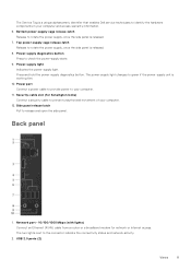
... enables Dell service technicians to green if the power-supply unit is released. 7. The power-supply light changes to identify the hardware components in your computer and access warranty information. 6. Side panel release latch Pull to the connector indicate the connectivity status and network activity. 2. The two lights next to release and open the side panel. Back panel 1. Press and hold the power-supply diagnostics button. Power port Connect a power cable to provide power to check the power‑supply state. 9. Network port...
... enables Dell service technicians to green if the power-supply unit is released. 7. The power-supply light changes to identify the hardware components in your computer and access warranty information. 6. Side panel release latch Pull to the connector indicate the connectivity status and network activity. 2. The two lights next to release and open the side panel. Back panel 1. Press and hold the power-supply diagnostics button. Power port Connect a power cable to provide power to check the power‑supply state. 9. Network port...

Setup and Specifications
Page 14
... 14 Specifications Memory specifications Slots Type Speed Configurations supported: Per memory module slot Total memory Four UDIMM slots DDR4 ● Up to 2400 MHz: i3 processor ● Up to 2666 MHz: i5/i7/i7k processors 4 GB, 8 GB, and 16 GB 8 GB, 16 GB, 24 GB, 32 GB, and 64 GB The following requirements: ● 7th generation or higher Intel Core i3/i5/i7 processor ● Windows...
... 14 Specifications Memory specifications Slots Type Speed Configurations supported: Per memory module slot Total memory Four UDIMM slots DDR4 ● Up to 2400 MHz: i3 processor ● Up to 2666 MHz: i5/i7/i7k processors 4 GB, 8 GB, and 16 GB 8 GB, 16 GB, 24 GB, 32 GB, and 64 GB The following requirements: ● 7th generation or higher Intel Core i3/i5/i7 processor ● Windows...

Setup and Specifications
Page 15
Ports and connectors Back panel ports Network USB Video/Audio Table 10. Ports and connectors Front panel ports: Audio USB Card Reader Table 11. Supported Communications Ethernet Wireless 10/100/1000 Mbps Killer Ethernet controller integrated on system board ● Wi-Fi 802.11a/b/g/n ● Wi-Fi 802.11ac ● Bluetooth 4.1 Specifications 15 Ports and connectors Table 9. NOTE: For more information about enabling or disabling the Intel Optane memory, see Enabling Intel Optane memory or Disabling Intel Optane memory. Ports and connectors Internal ports: PCIe Slots M.2 Card One ...
Ports and connectors Back panel ports Network USB Video/Audio Table 10. Ports and connectors Front panel ports: Audio USB Card Reader Table 11. Supported Communications Ethernet Wireless 10/100/1000 Mbps Killer Ethernet controller integrated on system board ● Wi-Fi 802.11a/b/g/n ● Wi-Fi 802.11ac ● Bluetooth 4.1 Specifications 15 Ports and connectors Table 9. NOTE: For more information about enabling or disabling the Intel Optane memory, see Enabling Intel Optane memory or Disabling Intel Optane memory. Ports and connectors Internal ports: PCIe Slots M.2 Card One ...

Setup and Specifications
Page 16
.... Audio specifications Controller Integrated Realtek ALC3861 High Definition Audio with Waves MaxxAudio Pro Storage Table 15. Storage specifications Interface Hard drive Solid-state drive Optical drive (optional) Capacity: Hard drive SSD ● SATA 6 Gbps for optical drive ● SATA 6 Gbps for hard drive ● M.2 for SSD (SATA or PCIe/NVMe) Three 3.5-inch hard drives One M.2 slot One Slimline DVD+/-RW Up to 4 TB PCIe/NVMe: Up to 8 GB 16 Specifications Wireless module specifications Transfer rate Frequency bands supported...
.... Audio specifications Controller Integrated Realtek ALC3861 High Definition Audio with Waves MaxxAudio Pro Storage Table 15. Storage specifications Interface Hard drive Solid-state drive Optical drive (optional) Capacity: Hard drive SSD ● SATA 6 Gbps for optical drive ● SATA 6 Gbps for hard drive ● M.2 for SSD (SATA or PCIe/NVMe) Three 3.5-inch hard drives One M.2 slot One Slimline DVD+/-RW Up to 4 TB PCIe/NVMe: Up to 8 GB 16 Specifications Wireless module specifications Transfer rate Frequency bands supported...
Service Manual
Page 7
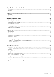
...card reader driver...86 Downloading the chipset driver...86 Downloading the network driver...86 Chapter 51: System setup...87 Boot Sequence...87 Navigation keys...87 BIOS overview...87 Entering BIOS setup program...87 System Setup Options...88 System and setup password...91 Assigning a system setup password...91 Deleting or changing an existing system setup password 91 Clearing CMOS settings...92 Clearing forgotten passwords...93 Chapter 52: Troubleshooting...96 Enhanced Pre-Boot System Assessment (ePSA) diagnostics 96 Running the ePSA Diagnostics...96 Diagnostics...96 Flashing BIOS (USB key...
...card reader driver...86 Downloading the chipset driver...86 Downloading the network driver...86 Chapter 51: System setup...87 Boot Sequence...87 Navigation keys...87 BIOS overview...87 Entering BIOS setup program...87 System Setup Options...88 System and setup password...91 Assigning a system setup password...91 Deleting or changing an existing system setup password 91 Clearing CMOS settings...92 Clearing forgotten passwords...93 Chapter 52: Troubleshooting...96 Enhanced Pre-Boot System Assessment (ePSA) diagnostics 96 Running the ePSA Diagnostics...96 Diagnostics...96 Flashing BIOS (USB key...

Service Manual
Page 8
... images in this document may require the following safety guidelines to the electrical outlet. NOTE: If you finish working inside the computer, replace all covers, panels, and screws before disconnecting the cable. Remove any connector pins. Unless otherwise noted, each procedure included in this document assumes that the work , periodically touch an unpainted metal surface to avoid bending any media card and optical disc from...
... images in this document may require the following safety guidelines to the electrical outlet. NOTE: If you finish working inside the computer, replace all covers, panels, and screws before disconnecting the cable. Remove any connector pins. Unless otherwise noted, each procedure included in this document assumes that the work , periodically touch an unpainted metal surface to avoid bending any media card and optical disc from...

Service Manual
Page 10
Replace any media cards, discs, or any external devices, peripherals, or cables you removed before working inside your computer. 3. Turn on your computer. 2. Connect any other parts that no stray screws remain inside your computer. 4. Replace all attached devices to their electrical outlets. 5. Connect your computer. 1. 2 After working inside your computer CAUTION: Leaving stray or loose screws inside your computer may severely damage your computer and all screws and ensure that you removed before working on your computer. 10 After working on your computer
Replace any media cards, discs, or any external devices, peripherals, or cables you removed before working inside your computer. 3. Turn on your computer. 2. Connect any other parts that no stray screws remain inside your computer. 4. Replace all attached devices to their electrical outlets. 5. Connect your computer. 1. 2 After working inside your computer CAUTION: Leaving stray or loose screws inside your computer may severely damage your computer and all screws and ensure that you removed before working on your computer. 10 After working on your computer

Service Manual
Page 82
...: Replacing the system board removes any changes you have made to the chassis. 4. You must enter the Service Tag in the BIOS setup program after you replace the system board. Remove the memory modules. 4. Remove the solid-state drive. 6. Remove the processor. For more safety best practices, see "System-board components". 2. Remove the graphics card. 5. Make note of the connectors so that shipped with your computer and follow the instructions in "Removing the power-supply unit...
...: Replacing the system board removes any changes you have made to the chassis. 4. You must enter the Service Tag in the BIOS setup program after you replace the system board. Remove the memory modules. 4. Remove the solid-state drive. 6. Remove the processor. For more safety best practices, see "System-board components". 2. Remove the graphics card. 5. Make note of the connectors so that shipped with your computer and follow the instructions in "Removing the power-supply unit...

Service Manual
Page 84
... 1. Replace the right-side cover. 84 Replacing the system board NOTE: Replacing the system board removes any changes you replace the system board. You must enter the Service Tag in After working inside your computer. Replace the processor. 2. Replace the graphics card. 6. Follow the procedure from the system board. NOTE: Your computer's Service Tag is stored in "Replacing the power-supply unit". 8. Route and connect the cables that secure the system board to the chassis. 3. Slide the I/O ports...
... 1. Replace the right-side cover. 84 Replacing the system board NOTE: Replacing the system board removes any changes you replace the system board. You must enter the Service Tag in After working inside your computer. Replace the processor. 2. Replace the graphics card. 6. Follow the procedure from the system board. NOTE: Your computer's Service Tag is stored in "Replacing the power-supply unit". 8. Route and connect the cables that secure the system board to the chassis. 3. Slide the I/O ports...

Service Manual
Page 85
... install the driver. Downloading drivers 85 NOTE: If you saved the USB 3.0 driver file. 8. Scroll down the page and expand Audio. 6. Click or tap Drivers & downloads > Find it myself. 5. Double-click or double-tap the graphics driver file icon and follow the instructions on the screen. Click or tap Product support enter the Service Tag of your computer, and then click or tap Submit. 50 Downloading drivers Downloading the audio driver 1. Turn...
... install the driver. Downloading drivers 85 NOTE: If you saved the USB 3.0 driver file. 8. Scroll down the page and expand Audio. 6. Click or tap Drivers & downloads > Find it myself. 5. Double-click or double-tap the graphics driver file icon and follow the instructions on the screen. Click or tap Product support enter the Service Tag of your computer, and then click or tap Submit. 50 Downloading drivers Downloading the audio driver 1. Turn...

Service Manual
Page 86
... where you do not have the Service Tag, use the auto-detect feature or manually browse for your computer model. 4. Go to download the network driver for your computer. 7. Click Download to www.dell.com/support. 3. Double-click the network driver file icon and follow the instructions on your computer. 2. Turn on screen. 86 Downloading drivers Downloading the chipset driver 1. Click Product support enter the Service Tag of your computer, and then...
... where you do not have the Service Tag, use the auto-detect feature or manually browse for your computer model. 4. Go to download the network driver for your computer. 7. Click Download to www.dell.com/support. 3. Double-click the network driver file icon and follow the instructions on your computer. 2. Turn on screen. 86 Downloading drivers Downloading the chipset driver 1. Click Product support enter the Service Tag of your computer, and then...

Service Manual
Page 87
... menu displays the devices that you can boot from including the diagnostic option. Navigation keys NOTE: For most of the System Setup options, changes that prompts you make are : • Removable Drive (if available) • STXXXX Drive NOTE: XXXX denotes the SATA drive number. • Optical Drive (if available) • SATA Hard Drive (if available) • Diagnostics NOTE: Choosing Diagnostics, displays the ePSA diagnostics screen. BIOS overview The BIOS manages data flow between the computer's operating system and attached devices such as hard disk, video adapter, keyboard, mouse...
... menu displays the devices that you can boot from including the diagnostic option. Navigation keys NOTE: For most of the System Setup options, changes that prompts you make are : • Removable Drive (if available) • STXXXX Drive NOTE: XXXX denotes the SATA drive number. • Optical Drive (if available) • SATA Hard Drive (if available) • Diagnostics NOTE: Choosing Diagnostics, displays the ePSA diagnostics screen. BIOS overview The BIOS manages data flow between the computer's operating system and attached devices such as hard disk, video adapter, keyboard, mouse...

Service Manual
Page 88
... the operating system logo appears, continue to wait until you to enter the service tag of hard drive installed. System setup options-Main menu System Memory Memory Speed Displays the current time in mm/dd/yyyy format. Displays the BIOS version number. Allows you to enable or disable Intel Speedstep Technology. Displays the processor L3 cache size. Displays the type of your computer. Displays the type of SSD installed. Displays the type of optical drive installed. System setup options-Advanced menu Advanced Advanced BIOS...
... the operating system logo appears, continue to wait until you to enter the service tag of hard drive installed. System setup options-Main menu System Memory Memory Speed Displays the current time in mm/dd/yyyy format. Displays the BIOS version number. Allows you to enable or disable Intel Speedstep Technology. Displays the processor L3 cache size. Displays the type of your computer. Displays the type of SSD installed. Displays the type of optical drive installed. System setup options-Advanced menu Advanced Advanced BIOS...

Service Manual
Page 89
... power is set the computer to turn on by Integrated LAN AC Recovery Deep Sleep Control USB Wake Support (S3) USB PowerShare (S4/S5) USB PowerShare Wake Support (S4/S5) Auto Power On Auto Power On Mode Auto Power On Date Auto Power On Time SupportAssist System Resolution Auto OS Recovery Threshold SupportAssist OS Recovery Allows you to Enabled hh:mm:ss. Performance Options Overclocking Feature System setup 89 Default: Disabled USB Configuration Front USB Ports Rear USB Ports Power Options Numlock Key Wake Up by special LAN...
... power is set the computer to turn on by Integrated LAN AC Recovery Deep Sleep Control USB Wake Support (S3) USB PowerShare (S4/S5) USB PowerShare Wake Support (S4/S5) Auto Power On Auto Power On Mode Auto Power On Date Auto Power On Time SupportAssist System Resolution Auto OS Recovery Threshold SupportAssist OS Recovery Allows you to Enabled hh:mm:ss. Performance Options Overclocking Feature System setup 89 Default: Disabled USB Configuration Front USB Ports Rear USB Ports Power Options Numlock Key Wake Up by special LAN...

Service Manual
Page 90
... to enable or disable the Legacy Option ROM. Displays the second boot device. Short Duration PWR Limit Options Allows you to set the turbo mode power limit. Allows you to permit or deny system password or HDD password changes. Enable or disable BIOS updates through UEFI capsule update packages. Default: Enabled. Allows you to delete the boot path in the boot option list. Displays the available boot devices. Default: Onboard NIC Device. Table 5. Core Voltage Mode Allows you to select between adaptive and...
... to enable or disable the Legacy Option ROM. Displays the second boot device. Short Duration PWR Limit Options Allows you to set the turbo mode power limit. Allows you to permit or deny system password or HDD password changes. Enable or disable BIOS updates through UEFI capsule update packages. Default: Enabled. Allows you to delete the boot path in the boot option list. Displays the available boot devices. Default: Onboard NIC Device. Table 5. Core Voltage Mode Allows you to select between adaptive and...

Service Manual
Page 96
... the basic computer requirements and the hardware is launched by either of LED flashes 1 Problem description System board: BIOS and ROM failure 2 No memory or RAM detected 96 Troubleshooting NOTE: The Enhanced Pre-boot System Assessment window displays, listing all the detected devices. 4. The diagnostics starts running the tests on a specific device, press Esc and click Yes to select the Diagnostics option and then press Enter. Note the error code and contact Dell. If the computer passes the...
... the basic computer requirements and the hardware is launched by either of LED flashes 1 Problem description System board: BIOS and ROM failure 2 No memory or RAM detected 96 Troubleshooting NOTE: The Enhanced Pre-boot System Assessment window displays, listing all the detected devices. 4. The diagnostics starts running the tests on a specific device, press Esc and click Yes to select the Diagnostics option and then press Enter. Note the error code and contact Dell. If the computer passes the...

Service Manual
Page 97
... System board failure No memory/RAM detected, system board, PSU System board, memory or processor failure Recovery image not found Recovery image found but invalid Flashing BIOS (USB key) 1. Click Drivers & downloads > Find it myself. 5. Click Download to download the latest BIOS setup program file. 2. Diagnostics (continued) Number of the BIOS for your computer. 6. Type the BIOS setup program filename and press Enter. 8. Follow these steps to troubleshoot and fix problems that needs the BIOS update. 5. NOTE: If you saved the BIOS update file. 9. Select the operating system installed...
... System board failure No memory/RAM detected, system board, PSU System board, memory or processor failure Recovery image not found Recovery image found but invalid Flashing BIOS (USB key) 1. Click Drivers & downloads > Find it myself. 5. Click Download to download the latest BIOS setup program file. 2. Diagnostics (continued) Number of the BIOS for your computer. 6. Type the BIOS setup program filename and press Enter. 8. Follow these steps to troubleshoot and fix problems that needs the BIOS update. 5. NOTE: If you saved the BIOS update file. 9. Select the operating system installed...

Service Manual
Page 100
... operating system Troubleshooting information, user manuals, setup instructions, product specifications, technical help blogs, drivers, software updates, and so on your product through one of computer concerns. NOTE: Availability varies by country and product, and some services may not be available in your product • Data backup • Troubleshooting and diagnostics • Factory and system restore • BIOS information In Windows search, type Contact Support, and press Enter. www.dell.com/support/windows www.dell.com/support...
... operating system Troubleshooting information, user manuals, setup instructions, product specifications, technical help blogs, drivers, software updates, and so on your product through one of computer concerns. NOTE: Availability varies by country and product, and some services may not be available in your product • Data backup • Troubleshooting and diagnostics • Factory and system restore • BIOS information In Windows search, type Contact Support, and press Enter. www.dell.com/support/windows www.dell.com/support...


