
Instruction Manual
Page 3
... of a cord suitable for outdoor use the cord for carrying, pulling or unplugging the power tool. Keep cord away from heat, oil, sharp edges or moving parts. Use of electric shock. 1 SAVE ALL WARNINGS AND INSTRUCTIONS FOR FUTURE REFERENCE The term "power tool" in electric shock, fire and/or serious injury. e) When operating a power tool outdoors, use an extension cord suitable for each signal word. English Definitions: Safety Guidelines...
... of a cord suitable for outdoor use the cord for carrying, pulling or unplugging the power tool. Keep cord away from heat, oil, sharp edges or moving parts. Use of electric shock. 1 SAVE ALL WARNINGS AND INSTRUCTIONS FOR FUTURE REFERENCE The term "power tool" in electric shock, fire and/or serious injury. e) When operating a power tool outdoors, use an extension cord suitable for each signal word. English Definitions: Safety Guidelines...

Instruction Manual
Page 4
... of electric shock. 3) PERSONAL SAFETY a) Stay alert, watch what you are caused by a qualified repair person using only identical replacement parts. Always wear eye protection. Carrying power tools with your hair, clothing and gloves away from moving parts, breakage of the power tool may result in serious personal injury. A wrench or a key left attached to a rotating part of parts and any adjustments, changing accessories, or storing power tools. Properly maintained cutting tools...
... of electric shock. 3) PERSONAL SAFETY a) Stay alert, watch what you are caused by a qualified repair person using only identical replacement parts. Always wear eye protection. Carrying power tools with your hair, clothing and gloves away from moving parts, breakage of the power tool may result in serious personal injury. A wrench or a key left attached to a rotating part of parts and any adjustments, changing accessories, or storing power tools. Properly maintained cutting tools...
Instruction Manual
Page 5
... of stopping flying debris generated by insulated gripping surfaces only, when performing an operation where the cutting accessory may result in electric shock, fire and/or serious injury. Prolonged exposure to function as abrasive wheels for chips and cracks, backing pad for cracks, tear or excess wear, wire brush for loose or cracked wires. i) Hold power tool by various operations. Read all instructions listed below...
... of stopping flying debris generated by insulated gripping surfaces only, when performing an operation where the cutting accessory may result in electric shock, fire and/or serious injury. Prolonged exposure to function as abrasive wheels for chips and cracks, backing pad for cracks, tear or excess wear, wire brush for loose or cracked wires. i) Hold power tool by various operations. Read all instructions listed below...

Instruction Manual
Page 6
... operator from the operator, depending on direction of your hand near flammable materials. b) Never place your control. d) Use special care when working corners, sharp edges etc. Safety Warnings Specific for Grinding and Abrasive Cutting-Off Operations a) Use only wheel types that could ignite these conditions. If you to a complete stop. The spinning accessory may kickback over kickback or torque reaction during start up. Using water or other accessory. Accessory...
... operator from the operator, depending on direction of your hand near flammable materials. b) Never place your control. d) Use special care when working corners, sharp edges etc. Safety Warnings Specific for Grinding and Abrasive Cutting-Off Operations a) Use only wheel types that could ignite these conditions. If you to a complete stop. The spinning accessory may kickback over kickback or torque reaction during start up. Using water or other accessory. Accessory...

Instruction Manual
Page 7
..., electrical wiring or objects that are intended for Polishing Operations a) Do not allow any loose attachment strings. d) Do not restart the cutting operation in the cut while the wheel is in the workpiece. e) Support panels or any reason, switch off wheel or apply excessive pressure. Flanges for recommended applications. b) Do not position your selected wheel. Supports must be used only for cut-off wheel from larger power tools. Safety...
..., electrical wiring or objects that are intended for Polishing Operations a) Do not allow any loose attachment strings. d) Do not restart the cutting operation in the cut while the wheel is in the workpiece. e) Support panels or any reason, switch off wheel or apply excessive pressure. Flanges for recommended applications. b) Do not position your selected wheel. Supports must be used only for cut-off wheel from larger power tools. Safety...
Instruction Manual
Page 8
... the gauge number, the heavier the cord. The wire bristles can result in injury. • Always use depending on this tool. Tighten the handle securely. Minimum Gauge for Cord Sets Ampere Rating Volts Total Length of Cord in loss of power and overheating. If this occurs, stop the tool and inspect the wheel for cracks or flaws. • Always handle and store wheels in a careful manner. • Never cut into...
... the gauge number, the heavier the cord. The wire bristles can result in injury. • Always use depending on this tool. Tighten the handle securely. Minimum Gauge for Cord Sets Ampere Rating Volts Total Length of Cord in loss of power and overheating. If this occurs, stop the tool and inspect the wheel for cracks or flaws. • Always handle and store wheels in a careful manner. • Never cut into...

Instruction Manual
Page 9
... or AC/DC...alternating or grounded) direct current Class II Construction no no load (double insulated) speed .../min .......... English WARNING: ALWAYS use face or dust mask if cutting operation is dusty. WARNING: Use of this type of harmful chemicals. WARNING: Always wear proper personal hearing protection that are NOT safety glasses. Always use , noise from power sanding, sawing, grinding, drilling, and other injury. Under some...
... or AC/DC...alternating or grounded) direct current Class II Construction no no load (double insulated) speed .../min .......... English WARNING: ALWAYS use face or dust mask if cutting operation is dusty. WARNING: Use of this type of harmful chemicals. WARNING: Always wear proper personal hearing protection that are NOT safety glasses. Always use , noise from power sanding, sawing, grinding, drilling, and other injury. Under some...
Instruction Manual
Page 10
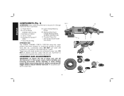
... . DO NOT use this tool. A. Quick-Change Backing Flange G2. Spindle Lock Button D. Dust Ejection System™ (DES) F. Anti-Vibration Side Handle (not shown) INTENDED USE The D28065, D26065N, D28115, D28115N heavy-duty angle grinders have been designed for professional grinding at various work sites (i.e., construction sites). Type 27 Guard E. ASSEMBLY AND ADJUSTMENTS WARNING: To reduce the risk of it from power source before installing and removing accessories, before adjusting or when...
... . DO NOT use this tool. A. Quick-Change Backing Flange G2. Spindle Lock Button D. Dust Ejection System™ (DES) F. Anti-Vibration Side Handle (not shown) INTENDED USE The D28065, D26065N, D28115, D28115N heavy-duty angle grinders have been designed for professional grinding at various work sites (i.e., construction sites). Type 27 Guard E. ASSEMBLY AND ADJUSTMENTS WARNING: To reduce the risk of it from power source before installing and removing accessories, before adjusting or when...

Instruction Manual
Page 11
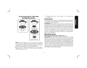
Use a wrench to motor housing. 3. Remove the four corner screws attaching the gear case to firmly tighten the side handle. Before using the tool, check that the handle is tightened securely. FIG. 2 I ) can be fitted to desired position. 9 Separating the gear case from tool. 2. 4-1/2" (114.3 mm) and 5" (127 mm) Grinding Wheels 6" (152 mm) Grinding Wheels English Type 27 guard Quick-Change backing flange Type 27 guard Type 27 hubbed wheel Type 27 depressed center wheel threaded clamp nut Attaching Side...
Use a wrench to motor housing. 3. Remove the four corner screws attaching the gear case to firmly tighten the side handle. Before using the tool, check that the handle is tightened securely. FIG. 2 I ) can be fitted to desired position. 9 Separating the gear case from tool. 2. 4-1/2" (114.3 mm) and 5" (127 mm) Grinding Wheels 6" (152 mm) Grinding Wheels English Type 27 guard Quick-Change backing flange Type 27 guard Type 27 hubbed wheel Type 27 depressed center wheel threaded clamp nut Attaching Side...

Instruction Manual
Page 12
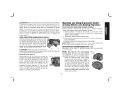
... Quick-Change backing flange Type 1 abrasive cutting wheel diamond cutting wheel threaded clamp nut threaded clamp nut Wire Wheels Type 27 guard Type 27 guard 3" (76.2 mm) wire cup brush 4" (101.6 mm) wire wheel 6" (152 mm) Cutting Wheels Type 1 guard Quick-Change backing flange Type 1 guard Quick-Change backing flange Type 27 guard stamped steel Quick-Change backing flange Type 1 abrasive cutting wheel threaded clamp nut Diamond cutting wheel threaded clamp nut Sanding Discs Type 27 depressed center wheel threaded clamp nut rubber backing pad sanding disc threaded clamp nut...
... Quick-Change backing flange Type 1 abrasive cutting wheel diamond cutting wheel threaded clamp nut threaded clamp nut Wire Wheels Type 27 guard Type 27 guard 3" (76.2 mm) wire cup brush 4" (101.6 mm) wire wheel 6" (152 mm) Cutting Wheels Type 1 guard Quick-Change backing flange Type 1 guard Quick-Change backing flange Type 27 guard stamped steel Quick-Change backing flange Type 1 abrasive cutting wheel threaded clamp nut Diamond cutting wheel threaded clamp nut Sanding Discs Type 27 depressed center wheel threaded clamp nut rubber backing pad sanding disc threaded clamp nut...
Instruction Manual
Page 13
... above listed minimum wheel speed as shown on the tool warning label. Some DEWALT models are included in ./lbs. (2.03 Nm) torque. Grinding and cutting with sanding flap discs (Type 27 and 29) and wire brushes. Threaded accessories must have a 5/8"-11 hub. Accessories It is designed for use with depressed center wheels (Type 27) and hubbed grinding wheels (Type 27). The tool may cause brush, motor and bearing failure. 4. Mounting instructions for these accessory guards are...
... above listed minimum wheel speed as shown on the tool warning label. Some DEWALT models are included in ./lbs. (2.03 Nm) torque. Grinding and cutting with sanding flap discs (Type 27 and 29) and wire brushes. Threaded accessories must have a 5/8"-11 hub. Accessories It is designed for use with depressed center wheels (Type 27) and hubbed grinding wheels (Type 27). The tool may cause brush, motor and bearing failure. 4. Mounting instructions for these accessory guards are...

Instruction Manual
Page 14
.... To remove the guard, open position. OPERATION WARNING: To reduce the risk of time, the guard becomes M loose, tighten the adjusting screw (M) with Type 27 wheels designed and specified for the correct accessories. Guards and Flanges It is closed position. English 1. The J guard body should not be performed with clamp lever in open , rotate the guard L (D) into the desired working position. Use only the accessories shown on the gear case...
.... To remove the guard, open position. OPERATION WARNING: To reduce the risk of time, the guard becomes M loose, tighten the adjusting screw (M) with Type 27 wheels designed and specified for the correct accessories. Guards and Flanges It is closed position. English 1. The J guard body should not be performed with clamp lever in open , rotate the guard L (D) into the desired working position. Use only the accessories shown on the gear case...
Instruction Manual
Page 15
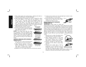
... the power supply, and has come to a complete stop . To unlock the tool, depress and release the trigger switch. SPINDLE LOCK (FIG. 6) The spindle lock (C) is for more information. 1. Operate the spindle lock only when the tool is turned off by pulling and twisting flange away form the machine. 2. FIG. 6 C Mounting and Using Depressed Center Grinding Wheels and Sanding Flap Discs MOUNTING AND REMOVING HUBBED WHEELS Hubbed wheels install directly on the spindle by hand. 3. Thread of accessory...
... the power supply, and has come to a complete stop . To unlock the tool, depress and release the trigger switch. SPINDLE LOCK (FIG. 6) The spindle lock (C) is for more information. 1. Operate the spindle lock only when the tool is turned off by pulling and twisting flange away form the machine. 2. FIG. 6 C Mounting and Using Depressed Center Grinding Wheels and Sanding Flap Discs MOUNTING AND REMOVING HUBBED WHEELS Hubbed wheels install directly on the spindle by hand. 3. Thread of accessory...
Instruction Manual
Page 16
... remove the wheel, depress the spindle lock button and loosen the threaded clamp nut with a Type 1 cut is begun and a notch is greatest when the tool operates at high speed. Grinding rate is tightened, check the orientation of the threaded clamp nut. Remove the tool from the operator. Allow the tool to avoid creating gouges in a forward and back motion to stop rotating before FIG. 9 turning tool off work surface. 5. For deeper cutting with a wrench...
... remove the wheel, depress the spindle lock button and loosen the threaded clamp nut with a Type 1 cut is begun and a notch is greatest when the tool operates at high speed. Grinding rate is tightened, check the orientation of the threaded clamp nut. Remove the tool from the operator. Allow the tool to avoid creating gouges in a forward and back motion to stop rotating before FIG. 9 turning tool off work surface. 5. For deeper cutting with a wrench...

Instruction Manual
Page 17
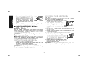
... the tool operates at high speed. Then depress the spindle lock button while turning the sanding disc until the sanding disc and clamp nut are complete. 1. To remove the wheel, grasp and turn the backing pad and sanding pad while O depressing the spindle lock button. Finer grits yield slower material removal and a smoother finish. Begin with a fine grit disc for grinding wheel, sanding flap disc, wire brush or wire wheel applications after sanding applications are snug. 5. MOUNTING SANDING BACKING PADS (FIG...
... the tool operates at high speed. Then depress the spindle lock button while turning the sanding disc until the sanding disc and clamp nut are complete. 1. To remove the wheel, grasp and turn the backing pad and sanding pad while O depressing the spindle lock button. Finer grits yield slower material removal and a smoother finish. Begin with a fine grit disc for grinding wheel, sanding flap disc, wire brush or wire wheel applications after sanding applications are snug. 5. MOUNTING SANDING BACKING PADS (FIG...
Instruction Manual
Page 18
... edge of flanges. Allowing the tool to tool or wheel. Depress spindle lock button and use a wrench on the spindle by hand. 2. CAUTION: Failure to properly seat the wheel hub before laying it down . CAUTION: Use extra care when working over an edge, as a sudden sharp movement of work surface. A Type 27 guard is greatest when the tool operates at high speed. MOUNTING WIRE BRUSHES AND WIRE WHEELS 1. Mounting and Using Wire Brushes and Wire Wheels Wire cup brushes or wire wheels screw directly on may be used for removing...
... edge of flanges. Allowing the tool to tool or wheel. Depress spindle lock button and use a wrench on the spindle by hand. 2. CAUTION: Failure to properly seat the wheel hub before laying it down . CAUTION: Use extra care when working over an edge, as a sudden sharp movement of work surface. A Type 27 guard is greatest when the tool operates at high speed. MOUNTING WIRE BRUSHES AND WIRE WHEELS 1. Mounting and Using Wire Brushes and Wire Wheels Wire cup brushes or wire wheels screw directly on may be used for removing...

Instruction Manual
Page 19
... the spindle lock button and tighten clamp nut with clamp lever in closed , 2-sided cutting wheel guard is required when using cutting wheels. English Mounting and Using Cutting (Type 1) Wheels (Fig. 1) Cutting wheels include diamond wheels and abrasive discs. MOUNTING CLOSED (TYPE 1) GUARD (FIG. 16, 17) 1. Undetectable damage to provide maximum operator protection. 4. The raised section (pilot) on the gear case cover. Wheel breakage and injury may result. CAUTION: Do not tighten adjusting screw M with a wrench. 5. USING CUTTING WHEELS (FIG. 18) WARNING: Do not use are...
... the spindle lock button and tighten clamp nut with clamp lever in closed , 2-sided cutting wheel guard is required when using cutting wheels. English Mounting and Using Cutting (Type 1) Wheels (Fig. 1) Cutting wheels include diamond wheels and abrasive discs. MOUNTING CLOSED (TYPE 1) GUARD (FIG. 16, 17) 1. Undetectable damage to provide maximum operator protection. 4. The raised section (pilot) on the gear case cover. Wheel breakage and injury may result. CAUTION: Do not tighten adjusting screw M with a wrench. 5. USING CUTTING WHEELS (FIG. 18) WARNING: Do not use are...

Instruction Manual
Page 20
.... 2. FIG. 18 MAINTENANCE WARNING: To reduce the risk of the cut is begun and a notch is required under the Federal Consumer Safety Act. To reduce the risk of the tool. Register online at least once a week. Remove the tool from your purchase. WARNING: Never use identical replacement parts. Accessories WARNING: Since accessories, other than those offered by a DEWALT factory service center, a DEWALT authorized service center or...
.... 2. FIG. 18 MAINTENANCE WARNING: To reduce the risk of the cut is begun and a notch is required under the Federal Consumer Safety Act. To reduce the risk of the tool. Register online at least once a week. Remove the tool from your purchase. WARNING: Never use identical replacement parts. Accessories WARNING: Since accessories, other than those offered by a DEWALT factory service center, a DEWALT authorized service center or...

Instruction Manual
Page 21
... - FREE WARNING LABEL REPLACEMENT: If your DEWALT Power Tool, Laser, or Nailer for any defects due to faulty materials or workmanship for three years from the date of warranty coverage and warranty repair information, visit www.dewalt.com or call 1-800-4-DEWALT (1-800433-9258). For products sold in Latin America. LATIN AMERICA: This warranty does not apply to accessories or damage caused where repairs have...
... - FREE WARNING LABEL REPLACEMENT: If your DEWALT Power Tool, Laser, or Nailer for any defects due to faulty materials or workmanship for three years from the date of warranty coverage and warranty repair information, visit www.dewalt.com or call 1-800-4-DEWALT (1-800433-9258). For products sold in Latin America. LATIN AMERICA: This warranty does not apply to accessories or damage caused where repairs have...

Instruction Manual
Page 72
DEWALT Industrial Tool Co., 701 East Joppa Road, Baltimore, MD 21286 (OCT12) Part No. N234380 D28065, D28065N, D28115, D28115N Copyright © 2007, 2012 DEWALT The following are trademarks for one or more DEWALT power tools: the yellow and black color scheme, the "D" shaped air intake grill, the array of pyramids on the handgrip, the kit box configuration, and the array of lozenge-shaped humps on the surface of the tool.
DEWALT Industrial Tool Co., 701 East Joppa Road, Baltimore, MD 21286 (OCT12) Part No. N234380 D28065, D28065N, D28115, D28115N Copyright © 2007, 2012 DEWALT The following are trademarks for one or more DEWALT power tools: the yellow and black color scheme, the "D" shaped air intake grill, the array of pyramids on the handgrip, the kit box configuration, and the array of lozenge-shaped humps on the surface of the tool.

