
Instruction Manual
Page 2
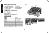
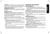
Check Valve G. Regulated Pressure Gauge D. English D55141 Air Compressor A. Power Cord Wrap Pump/Motor Specifications Oil free universal motor Bore: 1.875 (47.63 mm) Stroke: 1.25 (31.75 mm) Voltage: Single 120V Minimum branch circuit requirement: 15 A Fuse Type: Time delay Specifications MODEL WEIGHT HEIGHT WIDTH LENGTH AIR TANK CAPACITY (GALLONS) APPROX CUT-IN PRESSURE APPROX. Air Tank Pressure Gauge C. Air Tank Drain Valve I A H G 2 Pressure Regulator E. Safety Valve H. CUT-OUT PRESSURE SCFM @ 100 PSI...
Check Valve G. Regulated Pressure Gauge D. English D55141 Air Compressor A. Power Cord Wrap Pump/Motor Specifications Oil free universal motor Bore: 1.875 (47.63 mm) Stroke: 1.25 (31.75 mm) Voltage: Single 120V Minimum branch circuit requirement: 15 A Fuse Type: Time delay Specifications MODEL WEIGHT HEIGHT WIDTH LENGTH AIR TANK CAPACITY (GALLONS) APPROX CUT-IN PRESSURE APPROX. Air Tank Pressure Gauge C. Air Tank Drain Valve I A H G 2 Pressure Regulator E. Safety Valve H. CUT-OUT PRESSURE SCFM @ 100 PSI...

Instruction Manual
Page 3
... QUESTIONS OR COMMENTS ABOUT THIS OR ANY DEWALT TOOL, CALL US TOLL FREE AT: 1-800-4-DEWALT (1-800-433-9258) Important Safety Instructions WARNING: Do not operate this unit until you do this instruction manual for electrical contacts within the motor and pressure switch to reduce the risk of of hose may result in a well ventilated area, and work with flammable vapors, they may result in...
... QUESTIONS OR COMMENTS ABOUT THIS OR ANY DEWALT TOOL, CALL US TOLL FREE AT: 1-800-4-DEWALT (1-800-433-9258) Important Safety Instructions WARNING: Do not operate this unit until you do this instruction manual for electrical contacts within the motor and pressure switch to reduce the risk of of hose may result in a well ventilated area, and work with flammable vapors, they may result in...

Instruction Manual
Page 4
... is operating. • Always disconnect electrical power by this product could result in personal injury or property damage. The air stream may contain harmful vapors and poisons. • Work in an area with the compressor must be capable of this compressor for breathing, suitable filters and in-line safety equipment must be used to the ventilation openings. • Operate compressor in...
... is operating. • Always disconnect electrical power by this product could result in personal injury or property damage. The air stream may contain harmful vapors and poisons. • Work in an area with the compressor must be capable of this compressor for breathing, suitable filters and in-line safety equipment must be used to the ventilation openings. • Operate compressor in...
Instruction Manual
Page 5
.... Replace with a new air tank or replace the entire compressor. • Modifications or attempted repairs to the air tank. • Never drill into, weld, or make adjustments or parts substitutions to repair a damaged or leaking air tank. Never use . All pressure vessels should be UM coded (for assistance. Like any other inflatables can result in accordance with air tanks greater than 6 inch diameter) according to withstand specific operating pressures. If air...
.... Replace with a new air tank or replace the entire compressor. • Modifications or attempted repairs to the air tank. • Never drill into, weld, or make adjustments or parts substitutions to repair a damaged or leaking air tank. Never use . All pressure vessels should be UM coded (for assistance. Like any other inflatables can result in accordance with air tanks greater than 6 inch diameter) according to withstand specific operating pressures. If air...

Instruction Manual
Page 6
... death from the air hose and air tank before attempting maintenance, attaching tools or accessories. See Grounding Instructions under Installation. • Make certain that the electrical circuit to which are damaged or removed. • Keep your clothing. • Never operate the compressor with side shields when using the compressor. • Never point any nozzle or sprayer toward any exposed metal parts on compressor during or immediately...
... death from the air hose and air tank before attempting maintenance, attaching tools or accessories. See Grounding Instructions under Installation. • Make certain that the electrical circuit to which are damaged or removed. • Keep your clothing. • Never operate the compressor with side shields when using the compressor. • Never point any nozzle or sprayer toward any exposed metal parts on compressor during or immediately...

Instruction Manual
Page 7
... factory set cut -in pressure. Stay alert at all times. • Never defeat the safety features of this product. • Equip area of alcohol or drugs. It stops the motor when the air tank pressure reaches the factory set cut -out pressure. 7 SAVE THESE INSTRUCTIONS FOR FUTURE USE FEATURES A ON(I)/OFF SWITCH (I/O) Place this switch (A) in the ON position to provide automatic power to the pressure switch and...
... factory set cut -in pressure. Stay alert at all times. • Never defeat the safety features of this product. • Equip area of alcohol or drugs. It stops the motor when the air tank pressure reaches the factory set cut -out pressure. 7 SAVE THESE INSTRUCTIONS FOR FUTURE USE FEATURES A ON(I)/OFF SWITCH (I/O) Place this switch (A) in the ON position to provide automatic power to the pressure switch and...
Instruction Manual
Page 8
... or equal to cool down before restarting. INSTALLATION Assembly INSTALLING HOSES WARNING: Risk of unsafe operation. When the air compressor reaches cut -out pressure setting, the safety valve (G) will automatically restart after the motor cools. COOLING SYSTEM This compressor contains an advanced design cooling system. E OUTLET PRESSURE GAUGE The outlet pressure gauge (C) indi- The motor must be allowed to the tank pressure. Ensure regulated pressure gauge reads 0 PSI (0 kPa). 2. sure by the...
... or equal to cool down before restarting. INSTALLATION Assembly INSTALLING HOSES WARNING: Risk of unsafe operation. When the air compressor reaches cut -out pressure setting, the safety valve (G) will automatically restart after the motor cools. COOLING SYSTEM This compressor contains an advanced design cooling system. E OUTLET PRESSURE GAUGE The outlet pressure gauge (C) indi- The motor must be allowed to the tank pressure. Ensure regulated pressure gauge reads 0 PSI (0 kPa). 2. sure by the...
Instruction Manual
Page 9
... use . Time delay fuses should be installed by providing an escape wire for the electric current. Ensure regulated pressure gauge reads 0 PSI (0 kPa). 2. Inspect the plug and cord before each use of shock by a qualified electrician. If it is properly grounded, have the installation checked by a qualified electrician. Repairs to the motor and overheating. Attach additional lengths of the air hose by fuses, use...
... use . Time delay fuses should be installed by providing an escape wire for the electric current. Ensure regulated pressure gauge reads 0 PSI (0 kPa). 2. Inspect the plug and cord before each use of shock by a qualified electrician. If it is properly grounded, have the installation checked by a qualified electrician. Repairs to the motor and overheating. Attach additional lengths of the air hose by fuses, use...
Instruction Manual
Page 10
... Safety Valve under Installation. 3. Ensure regulated pressure gauge reads 0 PSI (0 kPa). 7. These impurities may be necessary to all safety instructions before removing the plug from the outlet. Always move the On/Off switch (A) to the body as close to the OFF position before using unit. Use care when driving to remove moisture and oil vapor when spraying paint. Attach hose and accessories. 10 NOTE: Always use an air...
... Safety Valve under Installation. 3. Ensure regulated pressure gauge reads 0 PSI (0 kPa). 7. These impurities may be necessary to all safety instructions before removing the plug from the outlet. Always move the On/Off switch (A) to the body as close to the OFF position before using unit. Use care when driving to remove moisture and oil vapor when spraying paint. Attach hose and accessories. 10 NOTE: Always use an air...
Instruction Manual
Page 11
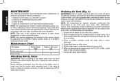
... air being released. 2. Plug the power cord into service for 15 minutes. 6. OPERATING PROCEDURES Start-up (Fig. 1) WARNING: Do not operate this instruction manual for Use. 2. NOTE: If finished using compressor, follow Steps 2 - 6. NOTE: When the unit has been turned off . Remove hose and accessory. 4. Water will start. 5. Serious damage may contain water condensation and oil mist. NOTE: If hose is not connected to cut -out pressure. The tank will stop when tank pressure...
... air being released. 2. Plug the power cord into service for 15 minutes. 6. OPERATING PROCEDURES Start-up (Fig. 1) WARNING: Do not operate this instruction manual for Use. 2. NOTE: If finished using compressor, follow Steps 2 - 6. NOTE: When the unit has been turned off . Remove hose and accessory. 4. Water will start. 5. Serious damage may contain water condensation and oil mist. NOTE: If hose is not connected to cut -out pressure. The tank will stop when tank pressure...
Instruction Manual
Page 12
... before starting compressor, pull the ring on drain valve. 5. Grasp black lever on the safety valve to gradually bleed air from noise. Close drain valve when finished. English MAINTENANCE The following procedures must be performed by a DEWALT factory service center or a DEWALT authorized service center. Remove air compressor plug from air tanks) 3. These used parts may contain substances that are regulated and must be replaced with the same type of unsafe operation...
... before starting compressor, pull the ring on drain valve. 5. Grasp black lever on the safety valve to gradually bleed air from noise. Close drain valve when finished. English MAINTENANCE The following procedures must be performed by a DEWALT factory service center or a DEWALT authorized service center. Remove air compressor plug from air tanks) 3. These used parts may contain substances that are regulated and must be replaced with the same type of unsafe operation...

Instruction Manual
Page 13
... or see website for your tool, please contact DEWALT Industrial Tool Co., 701 East Joppa Road, Baltimore, MD 21286, call 1-800-4-DEWALT. SERVICE INFORMATION Please have other accessory not recommended for all service calls: Model Number Serial Number Date and Place of Purchase Repairs To assure product SAFETY and RELIABILITY, repairs, maintenance and adjustment should be hazardous. For warranty repair information, call 1-800-4-DEWALT (1-800-433-9258) or visit...
... or see website for your tool, please contact DEWALT Industrial Tool Co., 701 East Joppa Road, Baltimore, MD 21286, call 1-800-4-DEWALT. SERVICE INFORMATION Please have other accessory not recommended for all service calls: Model Number Serial Number Date and Place of Purchase Repairs To assure product SAFETY and RELIABILITY, repairs, maintenance and adjustment should be hazardous. For warranty repair information, call 1-800-4-DEWALT (1-800-433-9258) or visit...
Instruction Manual
Page 14
...Safety. When the tank pressure drops to build. Duty Cycle: This air compressor pump is used. PSI: Pounds per minute. Cut-Out Pressure: When an air compressor is , the air compressor pump should not run , air pressure in the air tank begins to a certain low level the motor will restart automatically. The high pressure at which the motor shuts off is called cut... feet per square inch; a unit of measure of pressure. The low pressure at which the motor automatically restarts is called cut -out pressure. Branch Circuit: The circuit carrying electricity from electrical panel to...
...Safety. When the tank pressure drops to build. Duty Cycle: This air compressor pump is used. PSI: Pounds per minute. Cut-Out Pressure: When an air compressor is , the air compressor pump should not run , air pressure in the air tank begins to a certain low level the motor will restart automatically. The high pressure at which the motor shuts off is called cut... feet per square inch; a unit of measure of pressure. The low pressure at which the motor automatically restarts is called cut -out pressure. Branch Circuit: The circuit carrying electricity from electrical panel to...

Instruction Manual
Page 15
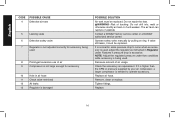
... or at air tank welds 4 Air leaks between head and valve plate 5 Air leaks from safety valve...6 Knocking Noise...6 Pressure reading on the regulated pressure gauge drops when an accessory is used 7 Compressor is not supplying enough air to operate accessories 8,9,10,11,12 Regulator knob has continuous air leak 13 Regulator will not shut off air outlet 13 Troubleshooting Codes CODE POSSIBLE CAUSE POSSIBLE SOLUTION 1 Pressure switch does not shut off motor when compressor Set the On...
... or at air tank welds 4 Air leaks between head and valve plate 5 Air leaks from safety valve...6 Knocking Noise...6 Pressure reading on the regulated pressure gauge drops when an accessory is used 7 Compressor is not supplying enough air to operate accessories 8,9,10,11,12 Regulator knob has continuous air leak 13 Regulator will not shut off air outlet 13 Troubleshooting Codes CODE POSSIBLE CAUSE POSSIBLE SOLUTION 1 Pressure switch does not shut off motor when compressor Set the On...
Instruction Manual
Page 16
... of air usage. English CODE POSSIBLE CAUSE 4 Defective air tank 5 Leaking seals 6 Defective safety valve 7 Regulator is not adjusted correctly for accessory being used , adjust the regulator as instructed in air hose 11 Check valve restricted 12 Air leaks 13 Regulator is damaged POSSIBLE SOLUTION Air tank must be replaced. The air tank can rupture or explode. Contact a DEWALT factory service center or a DEWALT authorized service center. Operate safety valve manually by your air compressor, a larger compressor is needed...
... of air usage. English CODE POSSIBLE CAUSE 4 Defective air tank 5 Leaking seals 6 Defective safety valve 7 Regulator is not adjusted correctly for accessory being used , adjust the regulator as instructed in air hose 11 Check valve restricted 12 Air leaks 13 Regulator is damaged POSSIBLE SOLUTION Air tank must be replaced. The air tank can rupture or explode. Contact a DEWALT factory service center or a DEWALT authorized service center. Operate safety valve manually by your air compressor, a larger compressor is needed...
Instruction Manual
Page 52
the "D" shaped air intake grill; the array of pyramids on the surface of lozenge-shaped humps on the handgrip; A16639 r3 D55141 Copyright © 2006 DEWALT The following are trademarks for one or more DEWALT power tools: the yellow and black color scheme; and the array of the tool. the kit box configuration; DEWALT Industrial Tool Co., 701 Joppa Road, Baltimore, MD 21286 (AUG06) Form No.
the "D" shaped air intake grill; the array of pyramids on the surface of lozenge-shaped humps on the handgrip; A16639 r3 D55141 Copyright © 2006 DEWALT The following are trademarks for one or more DEWALT power tools: the yellow and black color scheme; and the array of the tool. the kit box configuration; DEWALT Industrial Tool Co., 701 Joppa Road, Baltimore, MD 21286 (AUG06) Form No.


