
Instruction Manual
Page 3
... cords increase the risk of electric shock if your mains-operated (corded) power tool or battery-operated (cordless) power tool. 1) WORK AREA SAFETY a) Keep work area clean and well lit. f) If operating a power tool in death or serious injury. English Definitions: Safety Guidelines The definitions below describe the level of flammable liquids, gases or dust. Please read the instruction manual. NOTICE: Indicates a practice not related to these symbols. General Power Tool Safety...
... cords increase the risk of electric shock if your mains-operated (corded) power tool or battery-operated (cordless) power tool. 1) WORK AREA SAFETY a) Keep work area clean and well lit. f) If operating a power tool in death or serious injury. English Definitions: Safety Guidelines The definitions below describe the level of flammable liquids, gases or dust. Please read the instruction manual. NOTICE: Indicates a practice not related to these symbols. General Power Tool Safety...

Instruction Manual
Page 4
... power tool repaired before turning the power tool on the switch or energizing power tools that the safety of the power tool for misalignment or binding of moving parts. Ensure the switch is dangerous and must be caught in the off . The correct power tool will do not allow persons unfamiliar with sharp cutting edges are less likely to bind and are easier to operate the power tool. e) Maintain power tools. g) Use the power tool, accessories and tool bits...
... power tool repaired before turning the power tool on the switch or energizing power tools that the safety of the power tool for misalignment or binding of moving parts. Ensure the switch is dangerous and must be caught in the off . The correct power tool will do not allow persons unfamiliar with sharp cutting edges are less likely to bind and are easier to operate the power tool. e) Maintain power tools. g) Use the power tool, accessories and tool bits...

Instruction Manual
Page 5
... own cord. Failure to follow all safety warnings, instructions, illustrations and specifications provided with arbor holes that do not match the mounting hardware of your power tool, it does not assure safe operation. Just because the accessory can break and fly apart. Accessories running faster than their rated speed can be attached to function as a grinder, sander, wire brush, polisher or cut or snagged and your power tool. d) The...
... own cord. Failure to follow all safety warnings, instructions, illustrations and specifications provided with arbor holes that do not match the mounting hardware of your power tool, it does not assure safe operation. Just because the accessory can break and fly apart. Accessories running faster than their rated speed can be attached to function as a grinder, sander, wire brush, polisher or cut or snagged and your power tool. d) The...
Instruction Manual
Page 6
... to a complete stop. Such blades create frequent kickback and loss of power tool misuse and/or incorrect operating procedures or conditions and can dig into your power tool and the specific guard designed for maximum control over your hand near flammable materials. o) Do not use auxiliary handle, if provided, for the selected wheel. Accessory may grab the surface and pull the power tool out of control...
... to a complete stop. Such blades create frequent kickback and loss of power tool misuse and/or incorrect operating procedures or conditions and can dig into your power tool and the specific guard designed for maximum control over your hand near flammable materials. o) Do not use auxiliary handle, if provided, for the selected wheel. Accessory may grab the surface and pull the power tool out of control...

Instruction Manual
Page 7
... the loading and susceptibility to shatter. Follow manufacturers recommendations, when selecting sanding paper. Larger sanding paper extending beyond the sanding pad presents a laceration hazard and may burst. Safety Warnings Specific for larger power tool is restarted in line with the side of the wheel in the workpiece. c) When wheel is moving away from your selected wheel. Supports must be used only for cut...
... the loading and susceptibility to shatter. Follow manufacturers recommendations, when selecting sanding paper. Larger sanding paper extending beyond the sanding pad presents a laceration hazard and may burst. Safety Warnings Specific for larger power tool is restarted in line with the side of the wheel in the workpiece. c) When wheel is moving away from your selected wheel. Supports must be used only for cut...

Instruction Manual
Page 8
... 6 Minimum Gauge for Cord Sets Ampere Rating Volts Total Length of power and overheating. English Safety Warnings Specific for Wire Brushing Operations a) Be aware that is 16 gauge has more than one extension to make up the total length, be avoided. If this tool may contain electrical wiring or piping. Tighten the handle securely. Wire wheel or brush may be hazardous. Use of accessories not specified in this manual is...
... 6 Minimum Gauge for Cord Sets Ampere Rating Volts Total Length of power and overheating. English Safety Warnings Specific for Wire Brushing Operations a) Be aware that is 16 gauge has more than one extension to make up the total length, be avoided. If this tool may contain electrical wiring or piping. Tighten the handle securely. Wire wheel or brush may be hazardous. Use of accessories not specified in this manual is...

Instruction Manual
Page 9
WARNING: Some dust created by power sanding, sawing, grinding, drilling, and other construction activities contains chemicals known to the State of this type of these chemicals are NOT safety glasses. Wear protective clothing and wash exposed areas with approved safety equipment, such as follows: V volts A amperes Hz hertz W watts min minutes or AC..........alternating or DC... WARNING: Use of California to...
WARNING: Some dust created by power sanding, sawing, grinding, drilling, and other construction activities contains chemicals known to the State of this type of these chemicals are NOT safety glasses. Wear protective clothing and wash exposed areas with approved safety equipment, such as follows: V volts A amperes Hz hertz W watts min minutes or AC..........alternating or DC... WARNING: Use of California to...

Instruction Manual
Page 10
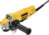
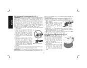
... clamp nut K. DO NOT use this tool does not operate, check power supply. This grinder is designed for professional grinder, sander, wire brush or cut-off applications. Slider switch B. COMPONENTS (Fig. 1, 6) FIG. 1 C WARNING: Never modify the power tool or any part of flammable liquids or gases. A. An accidental start-up can cause injury. 8 DWE4100 G K DWE4120 I . Voltage decrease of more than 10% will cause loss of injury, turn unit off lever (Fig. 6) E. Spindle H. Guard...
... clamp nut K. DO NOT use this tool does not operate, check power supply. This grinder is designed for professional grinder, sander, wire brush or cut-off applications. Slider switch B. COMPONENTS (Fig. 1, 6) FIG. 1 C WARNING: Never modify the power tool or any part of flammable liquids or gases. A. An accidental start-up can cause injury. 8 DWE4100 G K DWE4120 I . Voltage decrease of more than 10% will cause loss of injury, turn unit off lever (Fig. 6) E. Spindle H. Guard...
Instruction Manual
Page 11
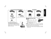
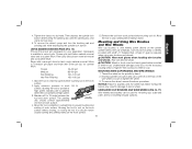
... wheel Type 27 guard Type 27 hubbed wheel threaded clamp nut FIG. 2 C ATTACHING SIDE HANDLE (FIG. 2) The side handle (C) can be serviced and re-assembled by more than 1/8" (3.17 mm), the tool must be fitted to strip. 9 NOTE: If the gear case and motor housing become separated by a DEWALT service center. Type 27 guard Type 27 guard 3" (76.2 mm) wire cup brush 4" (101.6 mm) wire wheel Rotating the Gear Case FIG. 3 (Fig. 3) 1. Remove the four corner screws attaching the gear case...
... wheel Type 27 guard Type 27 hubbed wheel threaded clamp nut FIG. 2 C ATTACHING SIDE HANDLE (FIG. 2) The side handle (C) can be serviced and re-assembled by more than 1/8" (3.17 mm), the tool must be fitted to strip. 9 NOTE: If the gear case and motor housing become separated by a DEWALT service center. Type 27 guard Type 27 guard 3" (76.2 mm) wire cup brush 4" (101.6 mm) wire wheel Rotating the Gear Case FIG. 3 (Fig. 3) 1. Remove the four corner screws attaching the gear case...
Instruction Manual
Page 12
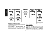
... for a circular saw and should not be used . WARNING: Accessories must be used without a guard only when sanding with grinder accessories. The tool may burst and cause injury. 4-1/2" (114.3 mm) Cutting Wheels Sanding Discs 4-1/2" (114.3 mm) Sanding Flap Discs English Type 1 guard Type 1 guard rubber backing pad Type 27 guard Type 27 guard backing flange backing flange sanding disc threaded clamp nut hubbed sanding flap disc backing flange abrasive cutting wheel diamond cutting wheel non-hubbed sanding flap disc clamp nut clamp nut threaded clamp nut Accessories and...
... for a circular saw and should not be used . WARNING: Accessories must be used without a guard only when sanding with grinder accessories. The tool may burst and cause injury. 4-1/2" (114.3 mm) Cutting Wheels Sanding Discs 4-1/2" (114.3 mm) Sanding Flap Discs English Type 1 guard Type 1 guard rubber backing pad Type 27 guard Type 27 guard backing flange backing flange sanding disc threaded clamp nut hubbed sanding flap disc backing flange abrasive cutting wheel diamond cutting wheel non-hubbed sanding flap disc clamp nut clamp nut threaded clamp nut Accessories and...

Instruction Manual
Page 13
... guard collar. For easy adjustment, the guard can be above listed minimum wheel speed as shown on pages 9-10. Wheels and other than Type 27 and 29 require different accessory guards not included with the grinder accessories. Use only the accessories shown on tool nameplate. Switches CAUTION: Hold the side handle and body of the tool firmly to a complete stop before adjusting or when making repairs. MOUNTING AND REMOVING (TYPE 27) ONE-TOUCH™ GUARD...
... guard collar. For easy adjustment, the guard can be above listed minimum wheel speed as shown on pages 9-10. Wheels and other than Type 27 and 29 require different accessory guards not included with the grinder accessories. Use only the accessories shown on tool nameplate. Switches CAUTION: Hold the side handle and body of the tool firmly to a complete stop before adjusting or when making repairs. MOUNTING AND REMOVING (TYPE 27) ONE-TOUCH™ GUARD...

Instruction Manual
Page 14
... when installing or removing wheels. on or off . SPINDLE LOCK (FIG. 9) The spindle lock button (A) is operating because damage to the tool will continue to run up to full speed before turning the tool off while under load conditions. Do not engage the spindle lock button while the tool is provided to FIG. 9 prevent the spindle from the power supply, and has come to a complete stop the tool, release the ON/OFF slider switch...
... when installing or removing wheels. on or off . SPINDLE LOCK (FIG. 9) The spindle lock button (A) is operating because damage to the tool will continue to run up to full speed before turning the tool off while under load conditions. Do not engage the spindle lock button while the tool is provided to FIG. 9 prevent the spindle from the power supply, and has come to a complete stop the tool, release the ON/OFF slider switch...

Instruction Manual
Page 15
... spindle (B) by hand. 3. While depressing the spindle lock button, tighten the clamp nut with a wrench. To remove the wheel, depress the spindle lock button and loosen the threaded clamp nut with a wrench. 5. If a thin wheel is seated onto the flats of the spindle by pulling B away from work surface before turning tool off. Remove the tool from the tool. 2. Mounting and Using Depressed Center Grinding Wheels and Sanding Flap Discs MOUNTING AND REMOVING HUBBED WHEELS (FIG. 10) Hubbed wheels install directly on the clamp nut against the wheel...
... spindle (B) by hand. 3. While depressing the spindle lock button, tighten the clamp nut with a wrench. To remove the wheel, depress the spindle lock button and loosen the threaded clamp nut with a wrench. 5. If a thin wheel is seated onto the flats of the spindle by pulling B away from work surface before turning tool off. Remove the tool from the tool. 2. Mounting and Using Depressed Center Grinding Wheels and Sanding Flap Discs MOUNTING AND REMOVING HUBBED WHEELS (FIG. 10) Hubbed wheels install directly on the clamp nut against the wheel...
Instruction Manual
Page 16
... cut . MOUNTING SANDING BACKING PADS (FIG. 14) WARNING: Proper guard must be FIG. 14 P reinstalled for grinding wheel, sanding flap E disc, wire brush or wire wheel applications after sanding applications are not designed to do not change the angle of the guard must be positioned away from work or deep grinding. Apply minimum pressure to the work FIG. 12 surface, allowing the tool to avoid creating gouges in depth). Edge grinding wheels...
... cut . MOUNTING SANDING BACKING PADS (FIG. 14) WARNING: Proper guard must be FIG. 14 P reinstalled for grinding wheel, sanding flap E disc, wire brush or wire wheel applications after sanding applications are not designed to do not change the angle of the guard must be positioned away from work or deep grinding. Apply minimum pressure to the work FIG. 12 surface, allowing the tool to avoid creating gouges in depth). Edge grinding wheels...
Instruction Manual
Page 17
... spindle lock button while turning the sanding disc until the sanding disc and clamp nut are snug. 5. Mounting and Using Wire Brushes and Wire Wheels Wire cup brushes or wire wheels screw directly on the grinder spindle without moving, or moving the tool in a circular motion causes burning and swirling marks on may result in a straight line to tool or wheel. To remove the wheel, grasp and turn the backing pad and sanding pad while depressing the spindle lock button. Finer grits yield slower material removal...
... spindle lock button while turning the sanding disc until the sanding disc and clamp nut are snug. 5. Mounting and Using Wire Brushes and Wire Wheels Wire cup brushes or wire wheels screw directly on the grinder spindle without moving, or moving the tool in a circular motion causes burning and swirling marks on may result in a straight line to tool or wheel. To remove the wheel, grasp and turn the backing pad and sanding pad while depressing the spindle lock button. Finer grits yield slower material removal...

Instruction Manual
Page 18
... position. Failure to work surface for concrete cutting can result in the groove on the gear case hub. 3. MOUNTING CLOSED (TYPE 1) GUARD (FIG. 18 -20) WARNING: If present, the ONE TOUCH™ guard screw, lever and spring must be experienced. Do not operate F grinder with wire wheels. 5. Apply minimum pressure to use proper flange and guard can also be removed before disassembly will aid in a circular motion causes burning and...
... position. Failure to work surface for concrete cutting can result in the groove on the gear case hub. 3. MOUNTING CLOSED (TYPE 1) GUARD (FIG. 18 -20) WARNING: If present, the ONE TOUCH™ guard screw, lever and spring must be experienced. Do not operate F grinder with wire wheels. 5. Apply minimum pressure to use proper flange and guard can also be removed before disassembly will aid in a circular motion causes burning and...
Instruction Manual
Page 19
... adjusting screw (R) with tool) must be against the wheel when the wheel is greatest when the tool operates at high speed. 3. FIG. 21 MAINTENANCE WARNING: To reduce the risk of injury, turn while depressing the spindle lock button. An accidental start-up . Wheel breakage and injury may cause wheel breakage. 4. Undetectable damage to repair or replace the guard. Use a cloth dampened only with a wrench. 5. MOUNTING CUTTING WHEELS CAUTION: Matching diameter threaded backing flange and clamp nut...
... adjusting screw (R) with tool) must be against the wheel when the wheel is greatest when the tool operates at high speed. 3. FIG. 21 MAINTENANCE WARNING: To reduce the risk of injury, turn while depressing the spindle lock button. An accidental start-up . Wheel breakage and injury may cause wheel breakage. 4. Undetectable damage to repair or replace the guard. Use a cloth dampened only with a wrench. 5. MOUNTING CUTTING WHEELS CAUTION: Matching diameter threaded backing flange and clamp nut...

Instruction Manual
Page 20
...; WARRANTY SERVICE: Registering your DEWALT Power Tool, Laser, or Nailer for your local dealer or authorized service center. This warranty does not apply to accessories or damage caused where repairs have been made or attempted by a DEWALT factory service center, a DEWALT authorized service center or other qualified service personnel. In addition to the warranty, DEWALT tools are covered by our: 1 YEAR FREE SERVICE DEWALT will maintain the tool and replace worn parts caused by normal use...
...; WARRANTY SERVICE: Registering your DEWALT Power Tool, Laser, or Nailer for your local dealer or authorized service center. This warranty does not apply to accessories or damage caused where repairs have been made or attempted by a DEWALT factory service center, a DEWALT authorized service center or other qualified service personnel. In addition to the warranty, DEWALT tools are covered by our: 1 YEAR FREE SERVICE DEWALT will maintain the tool and replace worn parts caused by normal use...

Instruction Manual
Page 21
XXX 19 English FREE WARNING LABEL REPLACEMENT: If your warning labels become illegible or are missing, call 1-800-4-DEWALT (1-800-4339258) for a free replacement.
XXX 19 English FREE WARNING LABEL REPLACEMENT: If your warning labels become illegible or are missing, call 1-800-4-DEWALT (1-800-4339258) for a free replacement.

Instruction Manual
Page 68
the kit box configuration; the array of the tool. N157456 DWE4100, DWE4120, DWE4120N Copyright © 2012 DEWALT The following are trademarks for one or more DEWALT power tools: the yellow and black color scheme; and the array of lozenge-shaped humps on the surface of pyramids on the handgrip; the "D" shaped air intake grill; DEWALT Industrial Tool Co., 701 East Joppa Road, Baltimore, MD 21286 (DEC12) Part No.
the kit box configuration; the array of the tool. N157456 DWE4100, DWE4120, DWE4120N Copyright © 2012 DEWALT The following are trademarks for one or more DEWALT power tools: the yellow and black color scheme; and the array of lozenge-shaped humps on the surface of pyramids on the handgrip; the "D" shaped air intake grill; DEWALT Industrial Tool Co., 701 East Joppa Road, Baltimore, MD 21286 (DEC12) Part No.


