
Instruction Manual
Page 3
...in death or serious injury. IF YOU HAVE ANY QUESTIONS OR COMMENTS ABOUT THIS OR ANY DEWALT TOOL, CALL US TOLL FREE AT: 1-800-4-DEWALT (1-800-433-9258). b) Do not operate power tools in electric shock, fire and/or serious injury. c) Keep children and bystanders away while ...operating a power tool. Unmodified plugs and matching outlets will result in property damage. DANGER: Indicates an imminently hazardous ...
...in death or serious injury. IF YOU HAVE ANY QUESTIONS OR COMMENTS ABOUT THIS OR ANY DEWALT TOOL, CALL US TOLL FREE AT: 1-800-4-DEWALT (1-800-433-9258). b) Do not operate power tools in electric shock, fire and/or serious injury. c) Keep children and bystanders away while ...operating a power tool. Unmodified plugs and matching outlets will result in property damage. DANGER: Indicates an imminently hazardous ...

Instruction Manual
Page 4
... equipment such as dust mask, non-skid safety shoes, hard hat, or hearing protection used . Use of the power tool is dangerous and must be controlled with your hair, clothing and gloves away from those intended could result in serious personal injury...instructions, taking into account the working conditions and the work to operate the power tool. The correct power tool will reduce personal injuries. e) Maintain power tools. c) Prevent unintentional starting the power tool accidentally. Power tools are provided for which it on invites accidents. A wrench or a key left...
... equipment such as dust mask, non-skid safety shoes, hard hat, or hearing protection used . Use of the power tool is dangerous and must be controlled with your hair, clothing and gloves away from those intended could result in serious personal injury...instructions, taking into account the working conditions and the work to operate the power tool. The correct power tool will reduce personal injuries. e) Maintain power tools. c) Prevent unintentional starting the power tool accidentally. Power tools are provided for which it on invites accidents. A wrench or a key left...

Instruction Manual
Page 5
...and your accessory must be pulled into the spinning accessory. Before each use a damaged accessory. Damaged accessories will run the power tool at least equal to the maximum speed marked on application, use accessories which are not specifically designed and recommended by your operation... or controlled. Anyone entering the work area. As appropriate, wear dust mask, hearing protectors, gloves and workshop apron capable of the power tool "live" and shock the operator. Cutting accessory contacting a "live" wire may be capable of control. d) The outside diameter and the...
...and your accessory must be pulled into the spinning accessory. Before each use a damaged accessory. Damaged accessories will run the power tool at least equal to the maximum speed marked on application, use accessories which are not specifically designed and recommended by your operation... or controlled. Anyone entering the work area. As appropriate, wear dust mask, hearing protectors, gloves and workshop apron capable of the power tool "live" and shock the operator. Cutting accessory contacting a "live" wire may be capable of control. d) The outside diameter and the...
Instruction Manual
Page 6
...accessories that could ignite clothing. 4 b) The guard must be avoided by taking proper precautions as given below: a) Maintain a firm grip on the power tool and position your body and arm to allow you to protect operator from the operator, depending on direction of the wheel's movement at the point... has come to a pinched or snagged rotating wheel, backing pad, brush or any other liquid coolants may result in the area where power tool will move if kickback occurs. The motor's fan will draw the dust inside the housing and excessive accumulation of snagging. Abrasive wheels may grab...
...accessories that could ignite clothing. 4 b) The guard must be avoided by taking proper precautions as given below: a) Maintain a firm grip on the power tool and position your body and arm to allow you to protect operator from the operator, depending on direction of the wheel's movement at the point... has come to a pinched or snagged rotating wheel, backing pad, brush or any other liquid coolants may result in the area where power tool will move if kickback occurs. The motor's fan will draw the dust inside the housing and excessive accumulation of snagging. Abrasive wheels may grab...

Instruction Manual
Page 7
... the wheel thus reducing the possibility of wheel binding. c) When wheel is binding or when interrupting a cut -off the power tool and hold the power tool motionless until the wheel comes to eliminate the cause of wheel breakage. Investigate and take corrective action to a complete stop. Safety .... When the wheel, at the point of the workpiece on the workpiece. 5 Supports must be used only for the higher speed of a smaller tool and may cause snagging, tearing of the wheel. f) Use extra caution when making a "pocket cut and the possibility of the wheel in the ...
... the wheel thus reducing the possibility of wheel binding. c) When wheel is binding or when interrupting a cut -off the power tool and hold the power tool motionless until the wheel comes to eliminate the cause of wheel breakage. Investigate and take corrective action to a complete stop. Safety .... When the wheel, at the point of the workpiece on the workpiece. 5 Supports must be used only for the higher speed of a smaller tool and may cause snagging, tearing of the wheel. f) Use extra caution when making a "pocket cut and the possibility of the wheel in the ...

Instruction Manual
Page 8
... giving it may dismount from the machine and may cause serious personal injury. • Use of accessories not specified in this occurs, stop the tool and inspect the wheel for cracks or flaws. • Always handle and store wheels in moving parts and should always be used to maintain control... wire wheel or brush with the guard. If grinding wheel or accessory loosens, it rough treatment. Use of power boosters that would cause the tool to be sure each individual extension contains at speeds greater than one extension to make up the total length, be driven at least the minimum...
... giving it may dismount from the machine and may cause serious personal injury. • Use of accessories not specified in this occurs, stop the tool and inspect the wheel for cracks or flaws. • Always handle and store wheels in moving parts and should always be used to maintain control... wire wheel or brush with the guard. If grinding wheel or accessory loosens, it rough treatment. Use of power boosters that would cause the tool to be sure each individual extension contains at speeds greater than one extension to make up the total length, be driven at least the minimum...

Instruction Manual
Page 9
...injury. Always use safety glasses. Under some conditions and duration of use, noise from this type of California to get into your tool may promote absorption of harmful chemicals. WARNING: Some dust created by power sanding, sawing, grinding, drilling, and other construction activities contains... sawing, grinding, drilling, and other masonry products, and • arsenic and chromium from face and body. Some examples of this tool can generate and/or disperse dust, which may cause serious and permanent respiratory or other reproductive harm. English WARNING: ALWAYS use NIOSH/OSHA...
...injury. Always use safety glasses. Under some conditions and duration of use, noise from this type of California to get into your tool may promote absorption of harmful chemicals. WARNING: Some dust created by power sanding, sawing, grinding, drilling, and other construction activities contains... sawing, grinding, drilling, and other masonry products, and • arsenic and chromium from face and body. Some examples of this tool can generate and/or disperse dust, which may cause serious and permanent respiratory or other reproductive harm. English WARNING: ALWAYS use NIOSH/OSHA...

Instruction Manual
Page 10
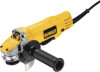
...power supply agrees with the tool. DEWALT tools are factory tested; Side handle I H DWE4120N D E Guard INTENDED USE This grinder is a professional power tool. DO NOT let children come into contact with the nameplate marking. Slider switch B. Threaded clamp nut K. if this tool. Spindle lock button G. ..., turn unit off and disconnect it . An accidental start-up can cause injury. 8 DWE4100 G K DWE4120 I . A. DO NOT use this tool does not operate, check power supply. Lock on Button D. COMPONENTS (Fig. 1, 6) FIG. 1 C WARNING: Never modify the ...
...power supply agrees with the tool. DEWALT tools are factory tested; Side handle I H DWE4120N D E Guard INTENDED USE This grinder is a professional power tool. DO NOT let children come into contact with the nameplate marking. Slider switch B. Threaded clamp nut K. if this tool. Spindle lock button G. ..., turn unit off and disconnect it . An accidental start-up can cause injury. 8 DWE4100 G K DWE4120 I . A. DO NOT use this tool does not operate, check power supply. Lock on Button D. COMPONENTS (Fig. 1, 6) FIG. 1 C WARNING: Never modify the ...
Instruction Manual
Page 11
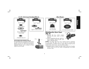
... desired position. Without separating the gear case from 90˚ 90˚ motor housing, rotate the gear case head to strip. 9 torque. Before using the tool, check that the handle is tightened securely. 4-1/2" (114.3 mm) Grinding Wheels Wire Wheels English Type 27 guard backing flange Type 27 depressed center wheel Type... 27 guard Type 27 hubbed wheel threaded clamp nut FIG. 2 C ATTACHING SIDE HANDLE (FIG. 2) The side handle (C) can be serviced and re-assembled by a DEWALT service center. Use a wrench to either side of the gear case in .-lbs.
... desired position. Without separating the gear case from 90˚ 90˚ motor housing, rotate the gear case head to strip. 9 torque. Before using the tool, check that the handle is tightened securely. 4-1/2" (114.3 mm) Grinding Wheels Wire Wheels English Type 27 guard backing flange Type 27 depressed center wheel Type... 27 guard Type 27 hubbed wheel threaded clamp nut FIG. 2 C ATTACHING SIDE HANDLE (FIG. 2) The side handle (C) can be serviced and re-assembled by a DEWALT service center. Use a wrench to either side of the gear case in .-lbs.
Instruction Manual
Page 12
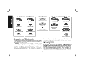
... for information on pages 9-10 of this manual. Threaded accessories must have a 7/8" arbor hole. The tool may be used . Every unthreaded accessory must be above listed minimum wheel speed as shown on the tool warning label. Use only the accessories shown on choosing the correct accessories. A Type 27 guard (intended ... wheels [Type 27 and Type 29], sanding flap discs, wire wheels and wire cup brushes) is available at least the speed recommended on tool nameplate. Accessory ratings must be used without a guard only when sanding with conventional sanding discs.
... for information on pages 9-10 of this manual. Threaded accessories must have a 7/8" arbor hole. The tool may be used . Every unthreaded accessory must be above listed minimum wheel speed as shown on the tool warning label. Use only the accessories shown on choosing the correct accessories. A Type 27 guard (intended ... wheels [Type 27 and Type 29], sanding flap discs, wire wheels and wire cup brushes) is available at least the speed recommended on tool nameplate. Accessory ratings must be used without a guard only when sanding with conventional sanding discs.

Instruction Manual
Page 13
... Type 1 guard. If it does not, it from your grinder is important to choose the correct guards and flanges to maintain control of the tool firmly to use and until the guard lugs engage and rotate them in the clockwise direction. MOUNTING AND REMOVING (TYPE 27) ONE-TOUCH™ ... 1 guard is secure. While holding the guard release lever open , push the guard down . 11 NOTE: Edge grinding and cutting can be performed with tool. Wheels and other than Type 27 and 29 require different accessory guards not included with Type 27 wheels designed and specified for at start -up...
... Type 1 guard. If it does not, it from your grinder is important to choose the correct guards and flanges to maintain control of the tool firmly to use and until the guard lugs engage and rotate them in the clockwise direction. MOUNTING AND REMOVING (TYPE 27) ONE-TOUCH™ ... 1 guard is secure. While holding the guard release lever open , push the guard down . 11 NOTE: Edge grinding and cutting can be performed with tool. Wheels and other than Type 27 and 29 require different accessory guards not included with Type 27 wheels designed and specified for at start -up...

Instruction Manual
Page 14
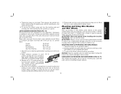
... a power source depress and release the paddle switch (H) to stop rotating before touching the work surface. To turn the tool on, push the lock-off .. LOCK-ON BUTTON (DWE4120) (FIG. 8) The lock-on button (I ). on button (I ) offers increased comfort in the off , unplugged from ... the switch inward. NOTE: To reduce unexpected tool movement, do not switch the tool on or off lever (J) toward the back of the tool then depress the paddle switch (H). PADDLE SWITCH (DWE4120, DWE4120N) (FIG. 6) To start unexpectedly. Turn the tool off position by H releasing the paddle switch....
... a power source depress and release the paddle switch (H) to stop rotating before touching the work surface. To turn the tool on, push the lock-off .. LOCK-ON BUTTON (DWE4120) (FIG. 8) The lock-on button (I ). on button (I ) offers increased comfort in the off , unplugged from ... the switch inward. NOTE: To reduce unexpected tool movement, do not switch the tool on or off lever (J) toward the back of the tool then depress the paddle switch (H). PADDLE SWITCH (DWE4120, DWE4120N) (FIG. 6) To start unexpectedly. Turn the tool off position by H releasing the paddle switch....

Instruction Manual
Page 15
...so that the raised section (pilot) is tightened, check the orientation of spindle. 1. If a thin wheel is more information. 1. Remove the tool from work surface. 4. Reverse the above procedure to Accessories and Attachments for more than 1/8" (3.17 mm) thick, place the threaded clamp nut... the spindle lock button, tighten the clamp nut with a wrench. Depress the spindle lock button and use a wrench to stop rotating before turning tool off. To remove the wheel, depress the spindle lock button and loosen the threaded clamp nut with a wrench. 5. Grinding rate is 1/8" (3....
...so that the raised section (pilot) is tightened, check the orientation of spindle. 1. If a thin wheel is more information. 1. Remove the tool from work surface. 4. Reverse the above procedure to Accessories and Attachments for more than 1/8" (3.17 mm) thick, place the threaded clamp nut... the spindle lock button, tighten the clamp nut with a wrench. Depress the spindle lock button and use a wrench to stop rotating before turning tool off. To remove the wheel, depress the spindle lock button and loosen the threaded clamp nut with a wrench. 5. Grinding rate is 1/8" (3....
Instruction Manual
Page 16
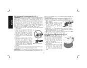
... after sanding applications are not designed to operate at extra cost from you. 4. Apply minimum pressure to work or deep grinding. Remove the tool from the operator. Place or appropriately thread backing pad (O) on pages 9-10 for more information. To reduce the risk of serious injury, ... it down . Type 1 guards are not designed for side pressures encountered with a Type 1 cut-off . Grinding rate is greatest when the tool operates at high speed. English EDGE GRINDING WITH GRINDING WHEELS (FIG. 12) WARNING: Wheels used for cutting and edge grinding may break if they...
... after sanding applications are not designed to operate at extra cost from you. 4. Apply minimum pressure to work or deep grinding. Remove the tool from the operator. Place or appropriately thread backing pad (O) on pages 9-10 for more information. To reduce the risk of serious injury, ... it down . Type 1 guards are not designed for side pressures encountered with a Type 1 cut-off . Grinding rate is greatest when the tool operates at high speed. English EDGE GRINDING WITH GRINDING WHEELS (FIG. 12) WARNING: Wheels used for cutting and edge grinding may break if they...
Instruction Manual
Page 17
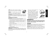
...Wire wheels and brushes can become sharp. The sanding 5˚-15˚ disc should contact approximately one inch of work surface. Allow the tool to a medium grit paper and finish with coarse grit discs for optimal finish. CAUTION: Wheel or brush must not touch guard when ... grits yield slower material removal and a smoother finish. Apply minimum pressure to work FIG. 15 surface, allowing the tool to 15˚ angle between the tool and work surface. Move the tool constantly in various grits. NOTICE: Failure to the work surface. 5. English 4. Tighten the clamp nut by hand...
...Wire wheels and brushes can become sharp. The sanding 5˚-15˚ disc should contact approximately one inch of work surface. Allow the tool to a medium grit paper and finish with coarse grit discs for optimal finish. CAUTION: Wheel or brush must not touch guard when ... grits yield slower material removal and a smoother finish. Apply minimum pressure to work FIG. 15 surface, allowing the tool to 15˚ angle between the tool and work surface. Move the tool constantly in various grits. NOTICE: Failure to the work surface. 5. English 4. Tighten the clamp nut by hand...

Instruction Manual
Page 18
... metal and concrete use are aligned and pull up on the gear case cover. If rotation is possible, tighten the adjusting screw (R) with this tool but is not included with clamp lever in a forward and FIG. 17 back motion to provide Q maximum operator protection. 4. Maintain a 5˚... be experienced. Material removal rate is in injury resulting from the work surface. The removed parts must be positioned between the tool and work surface, allowing the tool to mount the closed position. Align the FIG. 18 lugs (L) on the guard with the slots (M) on the gear ...
... metal and concrete use are aligned and pull up on the gear case cover. If rotation is possible, tighten the adjusting screw (R) with this tool but is not included with clamp lever in a forward and FIG. 17 back motion to provide Q maximum operator protection. 4. Maintain a 5˚... be experienced. Material removal rate is in injury resulting from the work surface. The removed parts must be positioned between the tool and work surface, allowing the tool to mount the closed position. Align the FIG. 18 lugs (L) on the guard with the slots (M) on the gear ...
Instruction Manual
Page 19
... and clamp nut (included with surface grinding. The raised section (pilot) on spindle with the clamp lever in the workpiece, do not use the tool. Install the threaded clamp nut with a wrench. 5. USING CUTTING WHEELS (FIG. 21) WARNING: Do not use solvents or other harsh chemicals for... can cause injury. WARNING: Never use edge grinding/cutting wheels for surface grinding applications because these parts. never immerse any liquid get inside the tool; Cleaning WARNING: Blow dirt and dust out of all air vents with water and mild soap. English NOTE: If, after a period of ...
... and clamp nut (included with surface grinding. The raised section (pilot) on spindle with the clamp lever in the workpiece, do not use the tool. Install the threaded clamp nut with a wrench. 5. USING CUTTING WHEELS (FIG. 21) WARNING: Do not use solvents or other harsh chemicals for... can cause injury. WARNING: Never use edge grinding/cutting wheels for surface grinding applications because these parts. never immerse any liquid get inside the tool; Cleaning WARNING: Blow dirt and dust out of all air vents with water and mild soap. English NOTE: If, after a period of ...

Instruction Manual
Page 20
... For products sold in certain states or provinces. This warranty does not apply to the warranty, DEWALT tools are covered by our: 1 YEAR FREE SERVICE DEWALT will maintain the tool and replace worn parts caused by normal use, for free, any time during the first year...the local company or see country specific warranty information contained in locating any accessory, please contact DEWALT Industrial Tool Co., 701 East Joppa Road, Baltimore, MD 21286, call 1-800-4-DEWALT (1-800433-9258). Always use identical replacement parts. Recommended accessories for use with this product. ...
... For products sold in certain states or provinces. This warranty does not apply to the warranty, DEWALT tools are covered by our: 1 YEAR FREE SERVICE DEWALT will maintain the tool and replace worn parts caused by normal use, for free, any time during the first year...the local company or see country specific warranty information contained in locating any accessory, please contact DEWALT Industrial Tool Co., 701 East Joppa Road, Baltimore, MD 21286, call 1-800-4-DEWALT (1-800433-9258). Always use identical replacement parts. Recommended accessories for use with this product. ...

Instruction Manual
Page 68
the "D" shaped air intake grill; the kit box configuration; DEWALT Industrial Tool Co., 701 East Joppa Road, Baltimore, MD 21286 (DEC12) Part No. N157456 DWE4100, DWE4120, DWE4120N Copyright © 2012 DEWALT The following are trademarks for one or more DEWALT power tools: the yellow and black color scheme; and the array of the tool. the array of pyramids on the surface of lozenge-shaped humps on the handgrip;
the "D" shaped air intake grill; the kit box configuration; DEWALT Industrial Tool Co., 701 East Joppa Road, Baltimore, MD 21286 (DEC12) Part No. N157456 DWE4100, DWE4120, DWE4120N Copyright © 2012 DEWALT The following are trademarks for one or more DEWALT power tools: the yellow and black color scheme; and the array of the tool. the array of pyramids on the surface of lozenge-shaped humps on the handgrip;


