
Instruction Manual
Page 5
... and may be cut -off tool. j) Position the cord clear of stopping small abrasive or workpiece fragments. b) Do not use inspect the accessory such as a grinder, sander, wire brush, polisher or cut or snagged and your operation. h) Keep bystanders a safe distance away from the plane of the rotating accessory and run...
... and may be cut -off tool. j) Position the cord clear of stopping small abrasive or workpiece fragments. b) Do not use inspect the accessory such as a grinder, sander, wire brush, polisher or cut or snagged and your operation. h) Keep bystanders a safe distance away from the plane of the rotating accessory and run...

Instruction Manual
Page 8
... injury. • Use of accessories not specified in doubt, use Type 11 (flaring cup) wheels on cord length and nameplate ampere rating. Minimum Gauge for Grinders WARNING: The grinding wheel or accessory may lead to loss of a guard is 16 gauge has more than its rated speed constitutes misuse. • Use...
... injury. • Use of accessories not specified in doubt, use Type 11 (flaring cup) wheels on cord length and nameplate ampere rating. Minimum Gauge for Grinders WARNING: The grinding wheel or accessory may lead to loss of a guard is 16 gauge has more than its rated speed constitutes misuse. • Use...

Instruction Manual
Page 10
... of power and overheating. An accidental start-up can cause injury. 8 DWE4100 G K DWE4120 I . Damage or personal injury could result. Spindle H. Guard release lever F. Guard INTENDED USE This grinder is a professional power tool. COMPONENTS (Fig. 1, 6) FIG. 1 C WARNING: Never... flange J. DO NOT let children come into contact with the nameplate marking. Threaded clamp nut K. DEWALT tools are factory tested; Slider switch B. This grinder is designed for professional grinder, sander, wire brush or cut-off lever (Fig. 6) E. F B A ASSEMBLY AND ADJUSTMENTS...
... of power and overheating. An accidental start-up can cause injury. 8 DWE4100 G K DWE4120 I . Damage or personal injury could result. Spindle H. Guard release lever F. Guard INTENDED USE This grinder is a professional power tool. COMPONENTS (Fig. 1, 6) FIG. 1 C WARNING: Never... flange J. DO NOT let children come into contact with the nameplate marking. Threaded clamp nut K. DEWALT tools are factory tested; Slider switch B. This grinder is designed for professional grinder, sander, wire brush or cut-off lever (Fig. 6) E. F B A ASSEMBLY AND ADJUSTMENTS...
Instruction Manual
Page 12
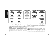
... speed as shown on pages 9-10 of this manual. Wheels and other accessories running over rated accessory speed may have been designed for use with grinder accessories.
... speed as shown on pages 9-10 of this manual. Wheels and other accessories running over rated accessory speed may have been designed for use with grinder accessories.

Instruction Manual
Page 13
...and cutting can be repositioned the opposite direction by using a Type 1 wheel and a Type 1 guard. If it does not, it from your grinder is important to choose the correct guards and flanges to provide maximum operator protection. 5. MOUNTING AND REMOVING (TYPE 27) ONE-TOUCH™ GUARD (FIG... wheel has come to maintain control of these instructions in the clockwise direction. For easy adjustment, the guard can be performed with the grinder accessories. Switches CAUTION: Hold the side handle and body of the tool firmly to a complete stop before mounting the guard. 1. A...
...and cutting can be repositioned the opposite direction by using a Type 1 wheel and a Type 1 guard. If it does not, it from your grinder is important to choose the correct guards and flanges to provide maximum operator protection. 5. MOUNTING AND REMOVING (TYPE 27) ONE-TOUCH™ GUARD (FIG... wheel has come to maintain control of these instructions in the clockwise direction. For easy adjustment, the guard can be performed with the grinder accessories. Switches CAUTION: Hold the side handle and body of the tool firmly to a complete stop before mounting the guard. 1. A...

Instruction Manual
Page 14
... spindle until you are unable to stop rotating before putting it is laid down . Allow the tool to rotate the spindle further. 12 PADDLE SWITCH (DWE4120, DWE4120N) (FIG. 6) To start the tool, slide the ON/OFF slider switch (G) toward the back of the switch inward. For continuous operation, slide the switch... in the off lever (J) toward the front of the tool and press the forward part of the tool, then depress the paddle switch (H). Allow the grinder to run up to run while the switch is depressed. To turn the tool on , push the FIG. 8 lock-off position by H releasing the ...
... spindle until you are unable to stop rotating before putting it is laid down . Allow the tool to rotate the spindle further. 12 PADDLE SWITCH (DWE4120, DWE4120N) (FIG. 6) To start the tool, slide the ON/OFF slider switch (G) toward the back of the switch inward. For continuous operation, slide the switch... in the off lever (J) toward the front of the tool and press the forward part of the tool, then depress the paddle switch (H). Allow the grinder to run up to run while the switch is depressed. To turn the tool on , push the FIG. 8 lock-off position by H releasing the ...
Instruction Manual
Page 17
... surface without the use of work surface. 4. Mounting and Using Wire Brushes and Wire Wheels Wire cup brushes or wire wheels screw directly on the grinder spindle without moving, or moving the tool in a circular motion causes burning and swirling marks on the hub of work surface. CAUTION: Wear work surface...
... surface without the use of work surface. 4. Mounting and Using Wire Brushes and Wire Wheels Wire cup brushes or wire wheels screw directly on the grinder spindle without moving, or moving the tool in a circular motion causes burning and swirling marks on the hub of work surface. CAUTION: Wear work surface...

Instruction Manual
Page 18
Material removal rate is required when using cutting wheels. Open the guard latch (Q). Do not operate F grinder with the slots (M) on the guard with a loose guard or clamp lever in reassembly. 1. Maintain a 5˚ to 10˚ angle between the edge ...open the guard latch, rotate the guard so that the arrows are available. See page 10 for wire cup brushes. 4. Noting the position of grinder may be removed before FIG. 16 touching the tool to avoid creating gouges in injury resulting from the work surface. 2. Abrasive cutting wheels for ...
Material removal rate is required when using cutting wheels. Open the guard latch (Q). Do not operate F grinder with the slots (M) on the guard with a loose guard or clamp lever in reassembly. 1. Maintain a 5˚ to 10˚ angle between the edge ...open the guard latch, rotate the guard so that the arrows are available. See page 10 for wire cup brushes. 4. Noting the position of grinder may be removed before FIG. 16 touching the tool to avoid creating gouges in injury resulting from the work surface. 2. Abrasive cutting wheels for ...


