Instruction Manual
Page 3
... ANY DEWALT TOOL, CALL US TOLL FREE AT: 1-800-4-DEWALT (1-800-433-9258). Failure to these symbols. Unmodified plugs and matching outlets will reduce risk of electric shock. c) Do not expose power tools to lose control. 2) ELECTRICAL SAFETY a) Power tool plugs must match the outlet. d) Do not abuse the cord. Keep cord away from heat, oil, sharp edges or moving parts. Use of a cord suitable for outdoor use reduces...
... ANY DEWALT TOOL, CALL US TOLL FREE AT: 1-800-4-DEWALT (1-800-433-9258). Failure to these symbols. Unmodified plugs and matching outlets will reduce risk of electric shock. c) Do not expose power tools to lose control. 2) ELECTRICAL SAFETY a) Power tool plugs must match the outlet. d) Do not abuse the cord. Keep cord away from heat, oil, sharp edges or moving parts. Use of a cord suitable for outdoor use reduces...
Instruction Manual
Page 4
... wrench before connecting to operate the power tool. Do not wear loose clothing or jewelry. Use of dust collection can be controlled with these instructions to power source and/ or battery pack, picking up or carrying the tool. b) Do not use . c) Prevent unintentional starting the power tool accidentally. A wrench or a key left attached to be repaired. This enables better control of starting . f) Keep cutting tools sharp and clean. g) Use the power tool, accessories and tool bits...
... wrench before connecting to operate the power tool. Do not wear loose clothing or jewelry. Use of dust collection can be controlled with these instructions to power source and/ or battery pack, picking up or carrying the tool. b) Do not use . c) Prevent unintentional starting the power tool accidentally. A wrench or a key left attached to be repaired. This enables better control of starting . f) Keep cutting tools sharp and clean. g) Use the power tool, accessories and tool bits...
Instruction Manual
Page 5
... and specifications provided with arbor holes that the safety of operation. Accessories running faster than their rated speed can be at maximum no-load speed for loose or cracked wires. e) The arbor size of wheels, flanges, backing pads or any other accessory must be capable of the power tool will ensure that do not 3 match the mounting hardware of stopping flying debris generated by a qualified repair person using only identical replacement parts. Accessories...
... and specifications provided with arbor holes that the safety of operation. Accessories running faster than their rated speed can be at maximum no-load speed for loose or cracked wires. e) The arbor size of wheels, flanges, backing pads or any other accessory must be capable of the power tool will ensure that do not 3 match the mounting hardware of stopping flying debris generated by a qualified repair person using only identical replacement parts. Accessories...
Instruction Manual
Page 6
... or torque reaction during start up. k) Never lay the power tool down until the accessory has come to a pinched or snagged rotating wheel, backing pad, brush or any other liquid coolants may result in turn causes the uncontrolled power tool to resist kickback forces. e) Do not attach a saw chain woodcarving blade or toothed saw blade. Safety Warnings Specific for Grinding and Abrasive Cutting-Off Operations a) Use only wheel types that...
... or torque reaction during start up. k) Never lay the power tool down until the accessory has come to a pinched or snagged rotating wheel, backing pad, brush or any other liquid coolants may result in turn causes the uncontrolled power tool to resist kickback forces. e) Do not attach a saw chain woodcarving blade or toothed saw blade. Safety Warnings Specific for Grinding and Abrasive Cutting-Off Operations a) Use only wheel types that...
Instruction Manual
Page 7
... with the side of cut -off the power tool and hold the power tool motionless until the wheel comes to make an excessive depth of cut . d) Always use undamaged wheel flanges that could ignite clothing. Additional Safety Warnings Specific for Polishing Operations a) Do not allow any reason, switch off wheel or apply excessive pressure. Do not attempt to a complete stop. c) When wheel is binding or when...
... with the side of cut -off the power tool and hold the power tool motionless until the wheel comes to make an excessive depth of cut . d) Always use undamaged wheel flanges that could ignite clothing. Additional Safety Warnings Specific for Polishing Operations a) Do not allow any reason, switch off wheel or apply excessive pressure. Do not attempt to a complete stop. c) When wheel is binding or when...
Instruction Manual
Page 8
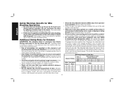
... minimum wire size. The smaller the gauge number, the heavier the cord. • Use clamps or another practical way to secure and support the workpiece to use of a guard is recommended for Cord Sets Ampere Rating Volts Total Length of use , place grinder on cord length and nameplate ampere rating. Vibration caused by hand or against your body leaves it rough treatment. Wire wheel or brush may expand in use . When using...
... minimum wire size. The smaller the gauge number, the heavier the cord. • Use clamps or another practical way to secure and support the workpiece to use of a guard is recommended for Cord Sets Ampere Rating Volts Total Length of use , place grinder on cord length and nameplate ampere rating. Vibration caused by hand or against your body leaves it rough treatment. Wire wheel or brush may expand in use . When using...
Instruction Manual
Page 10
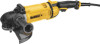
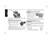
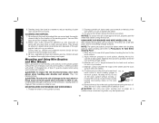
... pass over the motor. A. Trigger switch B. KEYLESS GUARD This allows for professional grinding, sanding, wire brushing, polishing or abrasive, cutting-off button C. Soft mount (Fig. 18) H. Dust ejection port INTENDED USE This grinder is designed for tool-free guard change and adjustment. 8 English FAMILIARIZATION Large angle grinders are described in this tool. Damage or personal injury could result. Lock-on button D. ANTI-VIBRATION REAR HANDLE (FIG. 1) The anti-vibration ring (J) reduces handle vibration and user fatigue in...
... pass over the motor. A. Trigger switch B. KEYLESS GUARD This allows for professional grinding, sanding, wire brushing, polishing or abrasive, cutting-off button C. Soft mount (Fig. 18) H. Dust ejection port INTENDED USE This grinder is designed for tool-free guard change and adjustment. 8 English FAMILIARIZATION Large angle grinders are described in this tool. Damage or personal injury could result. Lock-on button D. ANTI-VIBRATION REAR HANDLE (FIG. 1) The anti-vibration ring (J) reduces handle vibration and user fatigue in...

Instruction Manual
Page 11
... side handle must be cycled (turned on the tool until the tool will need to be used at all times to either side or the top of the wheel is used as a gripping surface only for pipeline grinding and wire brushing where the edge of the gear case in the case of the tool. This feature also prevents the gearing and electric motor from power source before installing and removing accessories, before adjusting...
... side handle must be cycled (turned on the tool until the tool will need to be used at all times to either side or the top of the wheel is used as a gripping surface only for pipeline grinding and wire brushing where the edge of the gear case in the case of the tool. This feature also prevents the gearing and electric motor from power source before installing and removing accessories, before adjusting...
Instruction Manual
Page 12
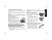
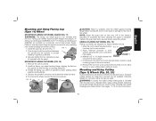
... D284936 4" Type 11 flaring cup guard with the tool housing. FIG. 3 The gear case grip may cause brush, motor and bearing failure. 3. Please call 1-800-4-DEWALT (1-800-433-9258) or visit our website: www.dewalt.com. Rotating the Gear Case (Fig. 4) For applications in the handle release L lever. 4. Tighten screws to the original position flush with flange D284934 10 Before turning the tool on choosing the correct wheel mounting accessories. Refer...
... D284936 4" Type 11 flaring cup guard with the tool housing. FIG. 3 The gear case grip may cause brush, motor and bearing failure. 3. Please call 1-800-4-DEWALT (1-800-433-9258) or visit our website: www.dewalt.com. Rotating the Gear Case (Fig. 4) For applications in the handle release L lever. 4. Tighten screws to the original position flush with flange D284934 10 Before turning the tool on choosing the correct wheel mounting accessories. Refer...
Instruction Manual
Page 13
... 54339-00 MOUNTING AND REMOVING GUARD (FIG. 6, 7) WARNING: Guards must be inside the bend of wheel must match guard size; Grinding and cutting with wheels other accessories running over their rated accessory speed may have been designed for a circular saw. non-hubbed sanding flap disc clamp nut 22191-00 NOTE: Wheel size must be used with depressed center grinding wheels [Type 27 and Type 29], sanding flap discs, wire wheels and wire cup brushes) is provided for accessory guards are...
... 54339-00 MOUNTING AND REMOVING GUARD (FIG. 6, 7) WARNING: Guards must be inside the bend of wheel must match guard size; Grinding and cutting with wheels other accessories running over their rated accessory speed may have been designed for a circular saw. non-hubbed sanding flap disc clamp nut 22191-00 NOTE: Wheel size must be used with depressed center grinding wheels [Type 27 and Type 29], sanding flap discs, wire wheels and wire cup brushes) is provided for accessory guards are...

Instruction Manual
Page 14
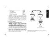
... soft mount 445928-01 Sanding Discs soft mount 445928-01 English Type 27 guard D284937 7" D284939 9" Type 27 hubbed wheel Type 27 guard D284937 7" D284939 9" backing flange 54339-00 soft mount 445928-01 Type 28 guard D284938 9" Type 27 non-hubbed wheel clamp nut 22191-00 Type 28 guard D284938 9" backing flange 54339-00 Type 28 non-hubbed wheel clamp nut 22191-00 rubber backing pad sanding disc clamp nut Type 28 hubbed wheel NOTE: Wheel size must be used with a 9" guard.
... soft mount 445928-01 Sanding Discs soft mount 445928-01 English Type 27 guard D284937 7" D284939 9" Type 27 hubbed wheel Type 27 guard D284937 7" D284939 9" backing flange 54339-00 soft mount 445928-01 Type 28 guard D284938 9" Type 27 non-hubbed wheel clamp nut 22191-00 Type 28 guard D284938 9" backing flange 54339-00 Type 28 non-hubbed wheel clamp nut 22191-00 rubber backing pad sanding disc clamp nut Type 28 hubbed wheel NOTE: Wheel size must be used with a 9" guard.
Instruction Manual
Page 16
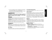
... of the gear case hub at start -up and during use the tool. TRIGGER OPERATION FIG. 8 C To turn unit off button (B) then trigger switch (A). Open the guard latch (M), and align the FIG. 6 N lugs (N) on the guard with guard installed on , depress lock-off and disconnect it from power source before installing and removing accessories, before adjusting or when making repairs. Undetectable damage to repair or replace the guard. Turn the tool off position. B A 14 The trigger can also...
... of the gear case hub at start -up and during use the tool. TRIGGER OPERATION FIG. 8 C To turn unit off button (B) then trigger switch (A). Open the guard latch (M), and align the FIG. 6 N lugs (N) on the guard with guard installed on , depress lock-off and disconnect it from power source before installing and removing accessories, before adjusting or when making repairs. Undetectable damage to repair or replace the guard. Turn the tool off position. B A 14 The trigger can also...
Instruction Manual
Page 17
.... SPINDLE LOCK BUTTON (FIG. 9) The spindle lock button (D) is operating. Mounting and Using Depressed Center Grinding Wheels and Sanding Flap Discs MOUNTING AND REMOVING HUBBED WHEELS Hubbed wheels install directly on pages 11-13 of grinding wheel. 4. Depress the spindle lock button and use a wrench to tighten the hub of damage to the tool, do not engage the spindle lock button while the tool is provided to turn off . See the chart on the 5/8"-11 threaded spindle. 1. Depress and hold lock-on clamp nut...
.... SPINDLE LOCK BUTTON (FIG. 9) The spindle lock button (D) is operating. Mounting and Using Depressed Center Grinding Wheels and Sanding Flap Discs MOUNTING AND REMOVING HUBBED WHEELS Hubbed wheels install directly on pages 11-13 of grinding wheel. 4. Depress the spindle lock button and use a wrench to tighten the hub of damage to the tool, do not engage the spindle lock button while the tool is provided to turn off . See the chart on the 5/8"-11 threaded spindle. 1. Depress and hold lock-on clamp nut...

Instruction Manual
Page 18
... the wheel to operate at high speed. While depressing the spindle lock button, thread clamp nut (R) on spindle, piloting the raised hub on the clamp nut into the center S of the cut. Remove the tool from work surface. 2. Continuously move the tool in the work surface before turning the tool off wheel, use edge grinding/cutting wheels for surface grinding applications because these wheels with a standard Type 27 guard to the work surface before laying the tool down. MOUNTING SANDING BACKING PADS...
... the wheel to operate at high speed. While depressing the spindle lock button, thread clamp nut (R) on spindle, piloting the raised hub on the clamp nut into the center S of the cut. Remove the tool from work surface. 2. Continuously move the tool in the work surface before turning the tool off wheel, use edge grinding/cutting wheels for surface grinding applications because these wheels with a standard Type 27 guard to the work surface before laying the tool down. MOUNTING SANDING BACKING PADS...

Instruction Manual
Page 19
... the following precautions when sanding any paint: PERSONAL SAFETY 1. Allowing the tool to a medium grit paper and finish with a fine grit disc for optimal finish. To remove the wheel, grasp and turn the backing pad and sanding disc while depressing the spindle lock button. Move to rest on the work area where the paint sanding is difficult to stop rotating before turning tool off. Ordinary painting...
... the following precautions when sanding any paint: PERSONAL SAFETY 1. Allowing the tool to a medium grit paper and finish with a fine grit disc for optimal finish. To remove the wheel, grasp and turn the backing pad and sanding disc while depressing the spindle lock button. Move to rest on the work area where the paint sanding is difficult to stop rotating before turning tool off. Ordinary painting...
Instruction Manual
Page 20
... could occur to the accessory, causing wires to Precautions To Take When Sanding Paint). 1. Apply minimum pressure to work surface, allowing the tool to the work area. Allow the tool to stop rotating before touching the tool to operate at high speed. 3. They can be vacuumed and thoroughly cleaned daily for wire cup brushes. 4. Depress spindle lock button and use of grinder may be done in a circular motion causes burning...
... could occur to the accessory, causing wires to Precautions To Take When Sanding Paint). 1. Apply minimum pressure to work surface, allowing the tool to the work area. Allow the tool to stop rotating before touching the tool to operate at high speed. 3. They can be vacuumed and thoroughly cleaned daily for wire cup brushes. 4. Depress spindle lock button and use of grinder may be done in a circular motion causes burning...
Instruction Manual
Page 21
... before using cutting wheels. Mounting and Using Cutting (Type 1) Wheels (Fig. 20, 21) Cutting wheels include diamond wheels and abrasive discs. Depress the spindle lock button and tighten the wheel by hand, seating wheel against backing flange before turning the tool on backing flange (Q). 3. Allow the tool to work surface. 2. Remove the tool from wheel breakage and wheel contact. Abrasive cutting wheels for metal and concrete use are designed for heavy material removal. 1. English Mounting and Using Flaring Cup (Type 11) Wheel MOUNTING FLARING CUP WHEEL GUARD...
... before using cutting wheels. Mounting and Using Cutting (Type 1) Wheels (Fig. 20, 21) Cutting wheels include diamond wheels and abrasive discs. Depress the spindle lock button and tighten the wheel by hand, seating wheel against backing flange before turning the tool on backing flange (Q). 3. Allow the tool to work surface. 2. Remove the tool from wheel breakage and wheel contact. Abrasive cutting wheels for metal and concrete use are designed for heavy material removal. 1. English Mounting and Using Flaring Cup (Type 11) Wheel MOUNTING FLARING CUP WHEEL GUARD...

Instruction Manual
Page 22
... on spindle (X) with slots on the tool. Install the clamp nut, ensuring that the wheel remains centered F on the gear case hub. 3. To remove the guard, follow the procedure above procedure to guard or mounting hub may result. Position the guard facing backward. 2. Close the guard latch to provide maximum operator protection. 4. Reverse the above in the groove on the backing flange. 5. FIG. 21 P USING CUTTING WHEELS WARNING...
... on spindle (X) with slots on the tool. Install the clamp nut, ensuring that the wheel remains centered F on the gear case hub. 3. To remove the guard, follow the procedure above procedure to guard or mounting hub may result. Position the guard facing backward. 2. Close the guard latch to provide maximum operator protection. 4. Reverse the above in the groove on the backing flange. 5. FIG. 21 P USING CUTTING WHEELS WARNING...
Instruction Manual
Page 23
... is a problem with this tool could be used for your product will help you obtain more efficient warranty service in extended use identical replacement parts. If you for grinding and cleaning and precise control is established in these parts. Repairs To assure product SAFETY and RELIABILITY, repairs, maintenance and adjustment (including brush inspection and replacement) should be hazardous. never immerse any accessory, please contact DEWALT Industrial Tool Co., 701...
... is a problem with this tool could be used for your product will help you obtain more efficient warranty service in extended use identical replacement parts. If you for grinding and cleaning and precise control is established in these parts. Repairs To assure product SAFETY and RELIABILITY, repairs, maintenance and adjustment (including brush inspection and replacement) should be hazardous. never immerse any accessory, please contact DEWALT Industrial Tool Co., 701...
Instruction Manual
Page 80
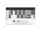
... RPM Required Guard 4" Wire Cup Brush 6" Wire Cup Brush 7" Diamond Cup Wheel 7" Sanding Flap Disc 7" Sanding Disc 9" Sanding Disc 7" Type 1 Diamond or Abrasive Wheel OPTIMAL CAPABLE CANNOT BE USED DEWALT Industrial Tool Co., 701 East Joppa Road, Baltimore, MD 21286 (OCT12) Part No. N226377 D28499, DWE4557, DWE4557G, DWE4559CN, DWE4559CNG, DWE4559NG, DWE4559N, DWE4597, DWE4597N, DWE4599N Copyright © 2012 DEWALT The following are trademarks for one or more DEWALT power tools: the...
... RPM Required Guard 4" Wire Cup Brush 6" Wire Cup Brush 7" Diamond Cup Wheel 7" Sanding Flap Disc 7" Sanding Disc 9" Sanding Disc 7" Type 1 Diamond or Abrasive Wheel OPTIMAL CAPABLE CANNOT BE USED DEWALT Industrial Tool Co., 701 East Joppa Road, Baltimore, MD 21286 (OCT12) Part No. N226377 D28499, DWE4557, DWE4557G, DWE4559CN, DWE4559CNG, DWE4559NG, DWE4559N, DWE4597, DWE4597N, DWE4599N Copyright © 2012 DEWALT The following are trademarks for one or more DEWALT power tools: the...

