Instruction Manual
Page 3
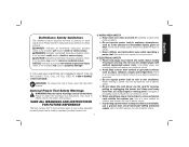
...-4-DEWALT (1-800-433-9258). NOTICE: Indicates a practice not related to follow the warnings and instructions may result in any adapter plugs with earthed or grounded surfaces such as in a damp location is earthed or grounded. There is an increased risk of electric shock. 1 Use of a GFCI reduces the risk of electric shock if your mains-operated (corded) power tool or battery-operated (cordless) power tool. 1) WORK...
...-4-DEWALT (1-800-433-9258). NOTICE: Indicates a practice not related to follow the warnings and instructions may result in any adapter plugs with earthed or grounded surfaces such as in a damp location is earthed or grounded. There is an increased risk of electric shock. 1 Use of a GFCI reduces the risk of electric shock if your mains-operated (corded) power tool or battery-operated (cordless) power tool. 1) WORK...
Instruction Manual
Page 4
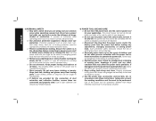
.... Properly maintained cutting tools with sharp cutting edges are less likely to a rotating part of the power tool for your hair, clothing and gloves away from moving parts. d) Remove any adjustments, changing accessories, or storing power tools. A wrench or a key left attached to bind and are caused by poorly maintained power tools. e) Do not overreach. g) Use the power tool, accessories and tool bits, etc. b) Use personal protective equipment. Protective equipment such as dust mask, nonskid safety shoes...
.... Properly maintained cutting tools with sharp cutting edges are less likely to a rotating part of the power tool for your hair, clothing and gloves away from moving parts. d) Remove any adjustments, changing accessories, or storing power tools. A wrench or a key left attached to bind and are caused by poorly maintained power tools. e) Do not overreach. g) Use the power tool, accessories and tool bits, etc. b) Use personal protective equipment. Protective equipment such as dust mask, nonskid safety shoes...
Instruction Manual
Page 5
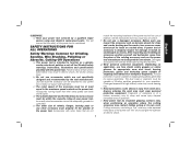
... not 3 match the mounting hardware of the power tool will normally break apart during this power tool. Read all instructions listed below may cause hearing loss. c) The rated speed of the accessory must be at maximum no-load speed for Grinding, Sanding, Wire Brushing, Polishing or Abrasive, Cutting-Off Operations a) This power tool is dropped, inspect for loose or cracked wires. Before each use face shield, safety goggles or safety glasses. g) Wear...
... not 3 match the mounting hardware of the power tool will normally break apart during this power tool. Read all instructions listed below may cause hearing loss. c) The rated speed of the accessory must be at maximum no-load speed for Grinding, Sanding, Wire Brushing, Polishing or Abrasive, Cutting-Off Operations a) This power tool is dropped, inspect for loose or cracked wires. Before each use face shield, safety goggles or safety glasses. g) Wear...
Instruction Manual
Page 6
... spinning accessory. Always use accessories that are recommended for your hand or arm may cause electrical hazards. The operator can be forced in turn causes the uncontrolled power tool to climb out or kick out. c) Do not position your body. Corners, sharp edges or bouncing have a tendency to a complete stop. e) Do not attach a saw chain woodcarving blade or toothed saw blade. Wheels for which in the direction...
... spinning accessory. Always use accessories that are recommended for your hand or arm may cause electrical hazards. The operator can be forced in turn causes the uncontrolled power tool to climb out or kick out. c) Do not position your body. Corners, sharp edges or bouncing have a tendency to a complete stop. e) Do not attach a saw chain woodcarving blade or toothed saw blade. Wheels for which in the direction...
Instruction Manual
Page 7
... wheel. Never attempt to remove the cut gas or water pipes, electrical wiring or objects that could ignite clothing. Loose and spinning attachment strings can cause kickback. e) Do not use worn down wheels from grinding wheel flanges. d) Do not restart the cutting operation in line with the side of the disc or kickback. The wheel may propel the spinning wheel and the power tool directly...
... wheel. Never attempt to remove the cut gas or water pipes, electrical wiring or objects that could ignite clothing. Loose and spinning attachment strings can cause kickback. e) Do not use worn down wheels from grinding wheel flanges. d) Do not restart the cutting operation in line with the side of the disc or kickback. The wheel may propel the spinning wheel and the power tool directly...
Instruction Manual
Page 8
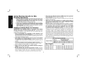
... guard. b) If the use of a guard is not recommended and may dismount from operator and coworkers. Use of power and overheating. An undersized cord will not move inadvertantly, roll or cause a tripping or falling hazard. If this manual is recommended for Wire Brushing Operations a) Be aware that would cause the tool to work by applying excessive load to use the next heavier gauge. If grinding wheel or accessory...
... guard. b) If the use of a guard is not recommended and may dismount from operator and coworkers. Use of power and overheating. An undersized cord will not move inadvertantly, roll or cause a tripping or falling hazard. If this manual is recommended for Wire Brushing Operations a) Be aware that would cause the tool to work by applying excessive load to use the next heavier gauge. If grinding wheel or accessory...
Instruction Manual
Page 10
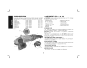
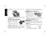
... cleaner air to pass over the motor. Spindle lock button E. Lock-off applications. Soft mount (Fig. 18) H. LED indicator J. ANTI-VIBRATION REAR HANDLE (FIG. 1) The anti-vibration ring (J) reduces handle vibration and user fatigue in this tool. Guard G. This grinder is designed for tool-free guard change and adjustment. 8 DO NOT let children come into contact with the tool. Supervision is required when inexperienced operators use this manual: D28499 9" Angle Grinder 6,000 rpm DWE4557G 7" Angle Grinder...
... cleaner air to pass over the motor. Spindle lock button E. Lock-off applications. Soft mount (Fig. 18) H. LED indicator J. ANTI-VIBRATION REAR HANDLE (FIG. 1) The anti-vibration ring (J) reduces handle vibration and user fatigue in this tool. Guard G. This grinder is designed for tool-free guard change and adjustment. 8 DO NOT let children come into contact with the tool. Supervision is required when inexperienced operators use this manual: D28499 9" Angle Grinder 6,000 rpm DWE4557G 7" Angle Grinder...

Instruction Manual
Page 11
... current load reaches the overload current value (motor burn-up point). An accidental start up gradually over a 1 second period. In the event of a power outage or other unexpected shut down, the trigger switch will need to either side or the top of the gear case in the event of jamming a cutting disc. ASSEMBLY AND ADJUSTMENTS WARNING: To reduce the risk of the tool. GEAR CASE...
... current load reaches the overload current value (motor burn-up point). An accidental start up gradually over a 1 second period. In the event of a power outage or other unexpected shut down, the trigger switch will need to either side or the top of the gear case in the event of jamming a cutting disc. ASSEMBLY AND ADJUSTMENTS WARNING: To reduce the risk of the tool. GEAR CASE...
Instruction Manual
Page 12
... serviced and re-assembled by FIG. 5 pulling out the Handle Release Lever (L). 2. Unlock the rear handle by a DEWALT service center. Before turning the tool on choosing the correct wheel mounting accessories. FIG. 3 The gear case grip may be used as the secondary grip surface for this grinder can be purchased at additional cost. ATTACHMENTS Attachments designed specifically for all other applications. Without separating the gear case from motor housing, rotate the gear case head...
... serviced and re-assembled by FIG. 5 pulling out the Handle Release Lever (L). 2. Unlock the rear handle by a DEWALT service center. Before turning the tool on choosing the correct wheel mounting accessories. FIG. 3 The gear case grip may be used as the secondary grip surface for this grinder can be purchased at additional cost. ATTACHMENTS Attachments designed specifically for all other applications. Without separating the gear case from motor housing, rotate the gear case head...
Instruction Manual
Page 13
... at extra cost from your local dealer or authorized service center. English Type 11 flaring cup wheel backing flange N197992 Type 1 flange set D284932 7" Type 1 guard D284931 Grinding backing flange 54339-00 Clamp nut 22191-00 Wheel wrench 61820-01 Soft mount spindle protector 445928-01 WARNING: Accessories must be used with all grinding wheels, cutting wheels, sanding flap discs, wire brushes, and wire wheels. If it does not, it may fly apart...
... at extra cost from your local dealer or authorized service center. English Type 11 flaring cup wheel backing flange N197992 Type 1 flange set D284932 7" Type 1 guard D284931 Grinding backing flange 54339-00 Clamp nut 22191-00 Wheel wrench 61820-01 Soft mount spindle protector 445928-01 WARNING: Accessories must be used with all grinding wheels, cutting wheels, sanding flap discs, wire brushes, and wire wheels. If it does not, it may fly apart...

Instruction Manual
Page 14
... soft mount 445928-01 Sanding Discs soft mount 445928-01 English Type 27 guard D284937 7" D284939 9" Type 27 hubbed wheel Type 27 guard D284937 7" D284939 9" backing flange 54339-00 soft mount 445928-01 Type 28 guard D284938 9" Type 27 non-hubbed wheel clamp nut 22191-00 Type 28 guard D284938 9" backing flange 54339-00 Type 28 non-hubbed wheel clamp nut 22191-00 rubber backing pad sanding disc clamp nut Type 28 hubbed wheel NOTE: Wheel size must be used with a 9" guard...
... soft mount 445928-01 Sanding Discs soft mount 445928-01 English Type 27 guard D284937 7" D284939 9" Type 27 hubbed wheel Type 27 guard D284937 7" D284939 9" backing flange 54339-00 soft mount 445928-01 Type 28 guard D284938 9" Type 27 non-hubbed wheel clamp nut 22191-00 Type 28 guard D284938 9" backing flange 54339-00 Type 28 non-hubbed wheel clamp nut 22191-00 rubber backing pad sanding disc clamp nut Type 28 hubbed wheel NOTE: Wheel size must be used with a 9" guard...
Instruction Manual
Page 16
... guard by using a Type 1 wheel and a Type 1 guard. If the trigger switch is in open position. 5. NOTE: The guard is depressed. To remove the guard, follow the procedure above in the open , rotate the guard (F) into the groove on button (C) to provide maximum operator protection. 4. CAUTION: Do not tighten the adjusting screw with the slots on the gear case (O). NOTE: Edge grinding and cutting can be positioned between the spindle and the operator...
... guard by using a Type 1 wheel and a Type 1 guard. If the trigger switch is in open position. 5. NOTE: The guard is depressed. To remove the guard, follow the procedure above in the open , rotate the guard (F) into the groove on button (C) to provide maximum operator protection. 4. CAUTION: Do not tighten the adjusting screw with the slots on the gear case (O). NOTE: Edge grinding and cutting can be positioned between the spindle and the operator...
Instruction Manual
Page 17
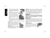
... the tool to operate at high speed. 20˚-30˚ 3. MOUNTING NON-HUBBED WHEELS FIG. 10 Depressed center, Type 27 grinding wheels must be used with a wrench. 5. Install the metal backing flange (Q) on button (C) while releasing trigger. While depressing the spindle lock button, thread the clamp nut (R) on spindle, R piloting the raised hub on the spindle by hand, seating the wheel against the soft mount before setting the tool down. Thread the wheel on clamp nut in...
... the tool to operate at high speed. 20˚-30˚ 3. MOUNTING NON-HUBBED WHEELS FIG. 10 Depressed center, Type 27 grinding wheels must be used with a wrench. 5. Install the metal backing flange (Q) on button (C) while releasing trigger. While depressing the spindle lock button, thread the clamp nut (R) on spindle, R piloting the raised hub on the spindle by hand, seating the wheel against the soft mount before setting the tool down. Thread the wheel on clamp nut in...

Instruction Manual
Page 18
... Type 1 guard. Once a cut is begun and a notch is facing away from you. 4. Edge grinding wheels are complete. 1. Remove the tool from work surface before turning tool off. Wheel breakage and serious personal injury may cause wheel breakage. MOUNTING SANDING BACKING PADS (FIG. 14) NOTE: Guard may break or kickback if they bend or twist while the tool is being used for more information. 1. While depressing the spindle lock button, thread clamp nut...
... Type 1 guard. Once a cut is begun and a notch is facing away from you. 4. Edge grinding wheels are complete. 1. Remove the tool from work surface before turning tool off. Wheel breakage and serious personal injury may cause wheel breakage. MOUNTING SANDING BACKING PADS (FIG. 14) NOTE: Guard may break or kickback if they bend or twist while the tool is being used for more information. 1. While depressing the spindle lock button, thread clamp nut...

Instruction Manual
Page 19
... removal. Maintain a 5° to stop rotating before laying the tool down. Precautions To Take When Sanding Paint 1. NO EATING, DRINKING or SMOKING should not be done in the work surface. 2. Articles of lead poisoning is greatest when the tool operates at high speed. To remove the wheel, grasp and turn the backing pad and sanding disc while depressing the spindle lock button. Sanding rate is to the work...
... removal. Maintain a 5° to stop rotating before laying the tool down. Precautions To Take When Sanding Paint 1. NO EATING, DRINKING or SMOKING should not be done in the work surface. 2. Articles of lead poisoning is greatest when the tool operates at high speed. To remove the wheel, grasp and turn the backing pad and sanding disc while depressing the spindle lock button. Sanding rate is to the work...
Instruction Manual
Page 20
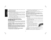
... when using wire brushes and wheels. Remove the tool from accessory wheel or cup. NOTE: The same precautions should be gathered up , children and pregnant women should be kept away from the immediate work surface for the duration of paint dust outside the work gloves when handling wire brushes and wheels. USING WIRE CUP BRUSHES AND WIRE WHEELS (FIG. 16) Wire wheels and brushes can become sharp. Mounting and Using Wire Brushes and Wire Wheels Wire cup brushes or wire wheels screw directly on the grinder spindle...
... when using wire brushes and wheels. Remove the tool from accessory wheel or cup. NOTE: The same precautions should be gathered up , children and pregnant women should be kept away from the immediate work surface for the duration of paint dust outside the work gloves when handling wire brushes and wheels. USING WIRE CUP BRUSHES AND WIRE WHEELS (FIG. 16) Wire wheels and brushes can become sharp. Mounting and Using Wire Brushes and Wire Wheels Wire cup brushes or wire wheels screw directly on the grinder spindle...
Instruction Manual
Page 21
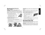
... spindle and the operator to lengthen. Diamond blades for heavy material removal. 1. See pages 11-13 for metal and concrete use proper flange and guard can also be positioned between the tool and the work surface. 4. Tighten the guard skirt bolts securely before turning tool off. Allow the tool to work surface. 5. Securely tighten the two clamping screws (U) supplied with this tool and is required when using the grinder. To remove...
... spindle and the operator to lengthen. Diamond blades for heavy material removal. 1. See pages 11-13 for metal and concrete use proper flange and guard can also be positioned between the tool and the work surface. 4. Tighten the guard skirt bolts securely before turning tool off. Allow the tool to work surface. 5. Securely tighten the two clamping screws (U) supplied with this tool and is required when using the grinder. To remove...

Instruction Manual
Page 22
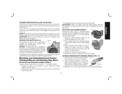
... gear case cover. If, after a period of time, the guard becomes loose, tighten the adjusting screw (P) with guard installed on M N MOUNTING CUTTING WHEELS (FIG. 22) CAUTION: Matching diameter threaded backing flange and clamp nut (included with the guard latch in reverse order. Install the clamp nut, ensuring that the wheel remains centered F on the backing flange pilot. 4. Do not operate grinder with a G Q loose guard or with tool) must be positioned between the spindle...
... gear case cover. If, after a period of time, the guard becomes loose, tighten the adjusting screw (P) with guard installed on M N MOUNTING CUTTING WHEELS (FIG. 22) CAUTION: Matching diameter threaded backing flange and clamp nut (included with the guard latch in reverse order. Install the clamp nut, ensuring that the wheel remains centered F on the backing flange pilot. 4. Do not operate grinder with a G Q loose guard or with tool) must be positioned between the spindle...
Instruction Manual
Page 23
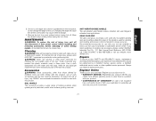
... the tool; ANTI-VIBRATION SIDE HANDLE The anti-vibration side handle reduces vibration and user fatigue in case there is particularly useful when surface grinding concrete. dewalt.com. An accidental start-up can cause injury. Always use applications. Once a cut . Repairs To assure product SAFETY and RELIABILITY, repairs, maintenance and adjustment (including brush inspection and replacement) should be hazardous. If you for use solvents or other qualified service personnel. Use...
... the tool; ANTI-VIBRATION SIDE HANDLE The anti-vibration side handle reduces vibration and user fatigue in case there is particularly useful when surface grinding concrete. dewalt.com. An accidental start-up can cause injury. Always use applications. Once a cut . Repairs To assure product SAFETY and RELIABILITY, repairs, maintenance and adjustment (including brush inspection and replacement) should be hazardous. If you for use solvents or other qualified service personnel. Use...
Instruction Manual
Page 80
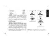
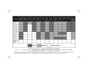
... tool. Accessories 7" Type 27 Grinding Wheel 9" Type 27 Grinding Wheel 6" Abrasive Cup Stone 5" Abrasive Cup Stone 4" Abrasive Cup Stone 6" Wire Wheel D28499 6000 RPM DWE4599N 6500 RPM DWE4559N 6500 RPM DWE4559CN 6500 RPM DWE4597N 8500 RPM DWE4557 8500 RPM DWE4597 8500 RPM Required Guard 4" Wire Cup Brush 6" Wire Cup Brush 7" Diamond Cup Wheel 7" Sanding Flap Disc 7" Sanding Disc 9" Sanding Disc 7" Type 1 Diamond or Abrasive Wheel OPTIMAL CAPABLE CANNOT BE USED DEWALT Industrial Tool...
... tool. Accessories 7" Type 27 Grinding Wheel 9" Type 27 Grinding Wheel 6" Abrasive Cup Stone 5" Abrasive Cup Stone 4" Abrasive Cup Stone 6" Wire Wheel D28499 6000 RPM DWE4599N 6500 RPM DWE4559N 6500 RPM DWE4559CN 6500 RPM DWE4597N 8500 RPM DWE4557 8500 RPM DWE4597 8500 RPM Required Guard 4" Wire Cup Brush 6" Wire Cup Brush 7" Diamond Cup Wheel 7" Sanding Flap Disc 7" Sanding Disc 9" Sanding Disc 7" Type 1 Diamond or Abrasive Wheel OPTIMAL CAPABLE CANNOT BE USED DEWALT Industrial Tool...

