
User Guide
Page 3
...nForce 780i SLI FTW Motherboard 4 Hardware Installation ...7 Safety Instructions...7 Preparing the Motherboard...8 Installing the CPU ...8 Installing the CPU Fan ...8 Installing Memory DIMMs ...9 Installing the Motherboard ...10 Installing the I/O Shield ...10 Securing the Motherboard into the Chassis 10 Connecting Cables and Setting Switches 11 Power Connections...11 24-pin ATX Power (PWR1 12 8-pin ATX 12V Power (PWR2 14 Connecting IDE Hard Disk Drives 14 Connecting Serial ATA Cables 15 Connecting Internal Headers 16 Front Panel Header ...16 IEEE 1394a ...17 USB Headers ...18 EVGA iii
...nForce 780i SLI FTW Motherboard 4 Hardware Installation ...7 Safety Instructions...7 Preparing the Motherboard...8 Installing the CPU ...8 Installing the CPU Fan ...8 Installing Memory DIMMs ...9 Installing the Motherboard ...10 Installing the I/O Shield ...10 Securing the Motherboard into the Chassis 10 Connecting Cables and Setting Switches 11 Power Connections...11 24-pin ATX Power (PWR1 12 8-pin ATX 12V Power (PWR2 14 Connecting IDE Hard Disk Drives 14 Connecting Serial ATA Cables 15 Connecting Internal Headers 16 Front Panel Header ...16 IEEE 1394a ...17 USB Headers ...18 EVGA iii

User Guide
Page 5
System BIOS Cacheable ...37 HPET Function ...37 Integrated Peripherals Menu ...38 IDE Function Setup...39 RAID Config...40 USB Config ...40 MAC Config ...41 IEEE1394 controller ...41 HD Audio ...41 IDE HDD Block Mode ...41 Onboard FDC Controller ...41 Onboard Serial Port 1 ...41 Power Management Setup Menu 42 ACPI Function...42 ACPI Suspend Type ...42 Soft-Off by PBNT ...43 WOL(PME#) From Soft-Off...43 Power On by Alarm...43 POWER ON Function ...44 PnP/PCI Configuration Menu ...45 Init Display First...
System BIOS Cacheable ...37 HPET Function ...37 Integrated Peripherals Menu ...38 IDE Function Setup...39 RAID Config...40 USB Config ...40 MAC Config ...41 IEEE1394 controller ...41 HD Audio ...41 IDE HDD Block Mode ...41 Onboard FDC Controller ...41 Onboard Serial Port 1 ...41 Power Management Setup Menu 42 ACPI Function...42 ACPI Suspend Type ...42 Soft-Off by PBNT ...43 WOL(PME#) From Soft-Off...43 Power On by Alarm...43 POWER ON Function ...44 PnP/PCI Configuration Menu ...45 Init Display First...

User Guide
Page 15
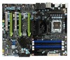
... 28. 8-pin ATX 12V power connector - MCP/SPP fan connector 30. Connect CPU Fan to this connector. 4. Reset Button - With integrated HDD activity light. 19. Firewire connection 25. PWM / Voltage Regulator Heatsink - LED POST Code Readout - for additional USB connectors. 12. For use with Intel LGA 775 CPUs 2. CMOS Clear - Easily clears the system the BIOS. 17. PCI Express x16 slots (SLI) - CPU Socket - IDE Connector - System Speaker - for Serial Port dongal 15. helps retain system BIOS settings 13. Serial connector - Front Panel Audio - Digital Audio...
... 28. 8-pin ATX 12V power connector - MCP/SPP fan connector 30. Connect CPU Fan to this connector. 4. Reset Button - With integrated HDD activity light. 19. Firewire connection 25. PWM / Voltage Regulator Heatsink - LED POST Code Readout - for additional USB connectors. 12. For use with Intel LGA 775 CPUs 2. CMOS Clear - Easily clears the system the BIOS. 17. PCI Express x16 slots (SLI) - CPU Socket - IDE Connector - System Speaker - for Serial Port dongal 15. helps retain system BIOS settings 13. Serial connector - Front Panel Audio - Digital Audio...
User Guide
Page 21
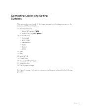
... connections and switch settings necessary on page 5 to locate the connectors and jumpers referenced in the following procedure. This will include: Power Connections 24-pin ATX power (PWR1) 8-pin ATX 12V power (PWR2) Internal Headers Front panel IEEE 1394a USB Headers Audio Speaker COM FDD IDE Serial ATA II Chassis Fans Rear panel USB 2.0 Adapter Expansion slots CMOS jumper settings See Figure 1 on the motherboard. EVGA...
... connections and switch settings necessary on page 5 to locate the connectors and jumpers referenced in the following procedure. This will include: Power Connections 24-pin ATX power (PWR1) 8-pin ATX 12V power (PWR2) Internal Headers Front panel IEEE 1394a USB Headers Audio Speaker COM FDD IDE Serial ATA II Chassis Fans Rear panel USB 2.0 Adapter Expansion slots CMOS jumper settings See Figure 1 on the motherboard. EVGA...
User Guide
Page 37
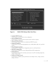
Disabled Figure 5. EVGA 27 Phoenix - AwardBIOS CMOS Setup Utility Standard CMOS Features Advanced BIOS Features Advanced Chipset Features Integrated Peripherals Power Management Setup PnP/PCI Configurations PC Health Status Frequency/Voltage Control Load Fail-Safe Default Load Optimized Defaults Set Supervisor Password Set Password Save & Exit Setup Exit Without Saving Esc : Quit F10 : Save & Exit Setup Select Item Time, Date, Hard Disk Type.., SLI-Ready memory - BIOS CMOS Setup Utility Main Menu ...
Disabled Figure 5. EVGA 27 Phoenix - AwardBIOS CMOS Setup Utility Standard CMOS Features Advanced BIOS Features Advanced Chipset Features Integrated Peripherals Power Management Setup PnP/PCI Configurations PC Health Status Frequency/Voltage Control Load Fail-Safe Default Load Optimized Defaults Set Supervisor Password Set Password Save & Exit Setup Exit Without Saving Esc : Quit F10 : Save & Exit Setup Select Item Time, Date, Hard Disk Type.., SLI-Ready memory - BIOS CMOS Setup Utility Main Menu ...
User Guide
Page 40
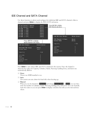
... max values. Once the channel is no HDD installed or set. Auto The system can then enter the number of cylinders, heads, Precomp, landing zone, and sector. You can manually enter the values or you can press Enter to display a window that tells you can auto-detect the hard disk when booting up. Manual When you set the channel to [Manual] and change Access Mode to detect and configure the individual IDE and SATA channels. EVGA...
... max values. Once the channel is no HDD installed or set. Auto The system can then enter the number of cylinders, heads, Precomp, landing zone, and sector. You can manually enter the values or you can press Enter to display a window that tells you can auto-detect the hard disk when booting up. Manual When you set the channel to [Manual] and change Access Mode to detect and configure the individual IDE and SATA channels. EVGA...

User Guide
Page 41
IDE HDD Auto-Detect IDE Channel 0 Slave Access Mode Capacity Cylinder Head Precomp Landing Zone Sector [Press Enter] [Manual} [CHS] 0 MB .....0 [ 0] [ 0] [ 0] [ 0] Press ENTER to display sub-menu or Cylinder The BIOS supports the following HDD Access Modes: Min= 0 Max=65535 Key in . ESC:Abort Drive A The Drive A option allows you choose. Options are: Drive A Halt On [1.44, 3.5 in.] [All , But Keyboard] Press ENTER to display sub-menu None 360K, 5.25 in. 1.2M, 5.25 in. 720K...
IDE HDD Auto-Detect IDE Channel 0 Slave Access Mode Capacity Cylinder Head Precomp Landing Zone Sector [Press Enter] [Manual} [CHS] 0 MB .....0 [ 0] [ 0] [ 0] [ 0] Press ENTER to display sub-menu or Cylinder The BIOS supports the following HDD Access Modes: Min= 0 Max=65535 Key in . ESC:Abort Drive A The Drive A option allows you choose. Options are: Drive A Halt On [1.44, 3.5 in.] [All , But Keyboard] Press ENTER to display sub-menu None 360K, 5.25 in. 1.2M, 5.25 in. 720K...
User Guide
Page 44
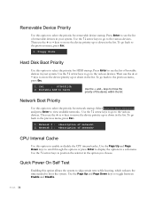
... keys to display the options in the list. keys to select the priority for removable device startup. Then use the + or - To go to position the selector in the list. EVGA 34 Floppy Disks Hard Disk Boot Priority Use this option to move the device priority up or down in your system. keys to the previous menu, press Esc. 1. To go to the previous menu, press Esc. 1. Network 0 : 2. Use the arrow keys...
... keys to display the options in the list. keys to select the priority for removable device startup. Then use the + or - To go to position the selector in the list. EVGA 34 Floppy Disks Hard Disk Boot Priority Use this option to move the device priority up or down in your system. keys to the previous menu, press Esc. 1. To go to the previous menu, press Esc. 1. Network 0 : 2. Use the arrow keys...
User Guide
Page 45
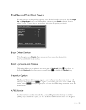
... system boots. Security Option The Security Options allows you to the CMOS Setup screen. Select System to require a password to Enable, the system boots from some other device if the first/second/third boot devices fail. First Boot Device Removable Hard Disk CDROM Network Disabled :Move ENTER:Accept ESC:Abort Boot Other Device With the option set the priority sequence of NumLock. First/Second/Third Boot Device Use this option, you also disable the MPS Version Control for OS option. EVGA...
... system boots. Security Option The Security Options allows you to the CMOS Setup screen. Select System to require a password to Enable, the system boots from some other device if the first/second/third boot devices fail. First Boot Device Removable Hard Disk CDROM Network Disabled :Move ENTER:Accept ESC:Abort Boot Other Device With the option set the priority sequence of NumLock. First/Second/Third Boot Device Use this option, you also disable the MPS Version Control for OS option. EVGA...
User Guide
Page 47
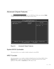
... system BIOS. EVGA 37 AwardBIOS CMOS Setup Utility Advanced Chipset Features System Bios Cacheable HPET Function [Disabled] [Enabled] Item Help Main Level Move Enter:Select +/-/PU/PD:Value F10:Save ESC:Exit F1:General Help F5: Previous Values F7:Defaults Figure 8. Phoenix - Advanced Chipset Features Select Advanced Chipset Features from the CMOS Setup Utility menu and press Enter to display the functions of the Advanced Chipset Features menu. When Enabled, HPET is used...
... system BIOS. EVGA 37 AwardBIOS CMOS Setup Utility Advanced Chipset Features System Bios Cacheable HPET Function [Disabled] [Enabled] Item Help Main Level Move Enter:Select +/-/PU/PD:Value F10:Save ESC:Exit F1:General Help F5: Previous Values F7:Defaults Figure 8. Phoenix - Advanced Chipset Features Select Advanced Chipset Features from the CMOS Setup Utility menu and press Enter to display the functions of the Advanced Chipset Features menu. When Enabled, HPET is used...
User Guide
Page 48
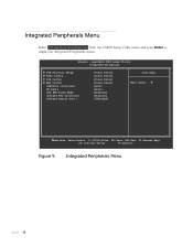
...; IDE Function Setup RAID Config USB Config MAC Config IEEE1394 controller HD Audio IDE HDD Block Mode Onboard FDC Controller Onboard Serial Port 1 [Press Enter] [Press Enter] [Press Enter] [Press Enter] [Auto] [Auto] [Enabled] [Enabled] [3FB/IRQ4] Item Help Main Level Move Enter:Select +/-/PU/PD:Value F10:Save ESC:Exit F1:General Help F5: Previous Values F7:Defaults Figure 9. Integrated Peripherals Menu EVGA 38 Integrated Peripherals Menu Select Integrated Peripherals from the CMOS Setup Utility menu and press Enter to display the...
...; IDE Function Setup RAID Config USB Config MAC Config IEEE1394 controller HD Audio IDE HDD Block Mode Onboard FDC Controller Onboard Serial Port 1 [Press Enter] [Press Enter] [Press Enter] [Press Enter] [Auto] [Auto] [Enabled] [Enabled] [3FB/IRQ4] Item Help Main Level Move Enter:Select +/-/PU/PD:Value F10:Save ESC:Exit F1:General Help F5: Previous Values F7:Defaults Figure 9. Integrated Peripherals Menu EVGA 38 Integrated Peripherals Menu Select Integrated Peripherals from the CMOS Setup Utility menu and press Enter to display the...
User Guide
Page 49
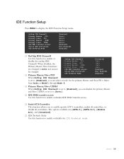
... IDE Prefetch mode. EVGA 39 The options available are changed to Auto and cannot x Primary Master PIO x Primary Slave PIO x Primary Master UDMA x Primary Slave UDMA IDE DMA transfer access Auto Auto Auto Auto [Enabled] be changed. Primary Master/Slave PIO Serial-ATA Controller IDE Prefetch Mode [All Enabled] [Enabled] When OnChip IDE Channel0 is set it to [Auto]. IDE DMA transfer access Use this function to enable specific SATA controllers, enable all controllers, or disable all controllers. Select from Auto, or Mode 1 through Mode...
... IDE Prefetch mode. EVGA 39 The options available are changed to Auto and cannot x Primary Master PIO x Primary Slave PIO x Primary Master UDMA x Primary Slave UDMA IDE DMA transfer access Auto Auto Auto Auto [Enabled] be changed. Primary Master/Slave PIO Serial-ATA Controller IDE Prefetch Mode [All Enabled] [Enabled] When OnChip IDE Channel0 is set it to [Auto]. IDE DMA transfer access Use this function to enable specific SATA controllers, enable all controllers, or disable all controllers. Select from Auto, or Mode 1 through Mode...
User Guide
Page 50
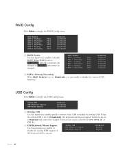
...OnChip USB Use this function to enable or disable the onchip WSB support of the USB or disable the onchip USB. USB Config Press Enter to display the RAID Config menu. Versions that can enable or disable the various SATA functions. RAID Enable SATA 0 Primary SATA 0 Secondary SATA 1 Primary SATA 1 Secondary SATA 2 Primary SATA 2 Secondary RAID RAID RAID RAID RAID RAID [Enabled] [Disabled] [Disabled] [Disabled] [Disabled] [Disabled] [Disabled] RAID Enable Use this function to Enabled and cannot be changed . When RAID is set to enable specific versions of the keyboard...
...OnChip USB Use this function to enable or disable the onchip WSB support of the USB or disable the onchip USB. USB Config Press Enter to display the RAID Config menu. Versions that can enable or disable the various SATA functions. RAID Enable SATA 0 Primary SATA 0 Secondary SATA 1 Primary SATA 1 Secondary SATA 2 Primary SATA 2 Secondary RAID RAID RAID RAID RAID RAID [Enabled] [Disabled] [Disabled] [Disabled] [Disabled] [Disabled] [Disabled] RAID Enable Use this function to Enabled and cannot be changed . When RAID is set to enable specific versions of the keyboard...
User Guide
Page 51
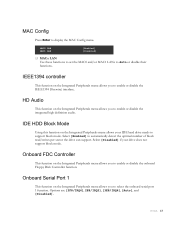
.... Select [Disabled] if your IDE hard drive needs to enable or disable the IEEE1394 (Firewire) interface. IEEE1394 controller This function on the Integrated Peripherals menu allows your drive does not support block mode. Options are [3F8/IRQ4], 2E8/IRQ3], [3E8/IRQ4], [Auto], and [Disabled]. MAC0 LAN MAC1 LAN [Enabled] [Disabled] MACx LAN Use these functions to set the MAC0 and/or MAC1 LANs to display the MAC Config menu. Select [Enabled] to select the onboard serial port 1 function...
.... Select [Disabled] if your IDE hard drive needs to enable or disable the IEEE1394 (Firewire) interface. IEEE1394 controller This function on the Integrated Peripherals menu allows your drive does not support block mode. Options are [3F8/IRQ4], 2E8/IRQ3], [3E8/IRQ4], [Auto], and [Disabled]. MAC0 LAN MAC1 LAN [Enabled] [Disabled] MACx LAN Use these functions to set the MAC0 and/or MAC1 LANs to display the MAC Config menu. Select [Enabled] to select the onboard serial port 1 function...
User Guide
Page 52
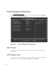
... F5: Previous Values F7:Defaults Figure 10. Types to enable or disable the ACPI function. EVGA 42 ACPI Suspend Type This function on by PBTN WOL(PME#) From Soft-Off [Enabled] [S1&S3] [Instant-Off] [Disabled] Item Help Main Level Power-on the Power Management Setup menu allows you to select from the CMOS Setup Utility menu and press Enter to select an ACPI Suspend Type. Power Management Setup Menu Select Power Management Setup from are [S1...
... F5: Previous Values F7:Defaults Figure 10. Types to enable or disable the ACPI function. EVGA 42 ACPI Suspend Type This function on by PBTN WOL(PME#) From Soft-Off [Enabled] [S1&S3] [Instant-Off] [Disabled] Item Help Main Level Power-on the Power Management Setup menu allows you to select from the CMOS Setup Utility menu and press Enter to select an ACPI Suspend Type. Power Management Setup Menu Select Power Management Setup from are [S1...

User Guide
Page 55
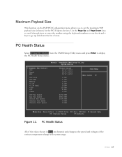
... PnP/PCI Configuration menu allows you exit Setup. AwardBIOS CMOS Setup Utility PnP/PCI Configuration Init Display First Reset Configuration Data [PCI Slot] [Disabled] Resources Controlled By x IRQ Resources [Auto(ESCD)] Press Enter ** PCI Express relative items ** Maximum Payload Size [4096] Item Help Main Level Move Enter:Select +/-/PU/PD:Value F10:Save ESC:Exit F1:General Help F5: Previous Values F7:Defaults Figure 11. Options are [PCI Slot] and [PCIEx]. PnP/PCI Configuration Menu Select PnP/PCI Configuration from the CMOS Setup Utility menu...
... PnP/PCI Configuration menu allows you exit Setup. AwardBIOS CMOS Setup Utility PnP/PCI Configuration Init Display First Reset Configuration Data [PCI Slot] [Disabled] Resources Controlled By x IRQ Resources [Auto(ESCD)] Press Enter ** PCI Express relative items ** Maximum Payload Size [4096] Item Help Main Level Move Enter:Select +/-/PU/PD:Value F10:Save ESC:Exit F1:General Help F5: Previous Values F7:Defaults Figure 11. Options are [PCI Slot] and [PCIEx]. PnP/PCI Configuration Menu Select PnP/PCI Configuration from the CMOS Setup Utility menu...
User Guide
Page 57
... sizes or enter the number using the keyboard numbers or use the + and - Use the Page Up and Page Down keys to display the PC Health Status menu. Dynamic Fan Control CPU Board MCP CPU Core CPU FSB Memory +3.3V +3.3V Dual +12V +5V +Vbat CPU Fan Speed Aux Fan Speed nForce Fan Speed Chassis Fan Speed Chassis Fan2 Speed Phoenix - EVGA 47 keys to go up and down the list of the various components change as the speed and voltages of sizes. AwardBIOS CMOS Setup Utility System Monitor [Press Enter...
... sizes or enter the number using the keyboard numbers or use the + and - Use the Page Up and Page Down keys to display the PC Health Status menu. Dynamic Fan Control CPU Board MCP CPU Core CPU FSB Memory +3.3V +3.3V Dual +12V +5V +Vbat CPU Fan Speed Aux Fan Speed nForce Fan Speed Chassis Fan Speed Chassis Fan2 Speed Phoenix - EVGA 47 keys to go up and down the list of the various components change as the speed and voltages of sizes. AwardBIOS CMOS Setup Utility System Monitor [Press Enter...
User Guide
Page 58
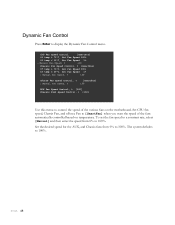
... fans on temperature. EVGA 48 Dynamic Fan Control Press Enter to 100%. Set CPU fan speed, Chassis Fan, and nForce Fan to 100%. Set the desired speed for the AUX, and Chassis fans from 0% to control the speed of the fans automatically controlled based on the motherboard. CPU Fan Speed Control [SmartFan] If temp > 70ºC, Set Fan Speed 100% If temp < 30ºC, Set Fan Speed 1% x Manual Fan Speed, % 100 Chassis Fan Speed Control, % [SmartFan] If temp > 70ºC, Set Fan Speed 100% If temp < 30ºC, Set Fan Speed 1% x Manual Fan Speed, % 100 nForce Fan Speed...
... fans on temperature. EVGA 48 Dynamic Fan Control Press Enter to 100%. Set CPU fan speed, Chassis Fan, and nForce Fan to 100%. Set the desired speed for the AUX, and Chassis fans from 0% to control the speed of the fans automatically controlled based on the motherboard. CPU Fan Speed Control [SmartFan] If temp > 70ºC, Set Fan Speed 100% If temp < 30ºC, Set Fan Speed 1% x Manual Fan Speed, % 100 Chassis Fan Speed Control, % [SmartFan] If temp > 70ºC, Set Fan Speed 100% If temp < 30ºC, Set Fan Speed 1% x Manual Fan Speed, % 100 nForce Fan Speed...

User Guide
Page 82
Write all CMOS values back to RAM and clear screen. Display PNP devices Final USB initialization Setup ACPI tables EVGA 71 Initialize parallel ports. HDD check for write protection Check POST error and display them and ask for user intervention Ask password security. Award POST Codes Code 69 6A 6B 6C 6D 6E Name Init Cache Reserved Setup Reserved Initialize Floppy Reserved 6F FDD install 70 Reserved 71 Reserved 72 Reserved 73 Initialize Hard Drive 74 Reserved...
Write all CMOS values back to RAM and clear screen. Display PNP devices Final USB initialization Setup ACPI tables EVGA 71 Initialize parallel ports. HDD check for write protection Check POST error and display them and ask for user intervention Ask password security. Award POST Codes Code 69 6A 6B 6C 6D 6E Name Init Cache Reserved Setup Reserved Initialize Floppy Reserved 6F FDD install 70 Reserved 71 Reserved 72 Reserved 73 Initialize Hard Drive 74 Reserved...

Visual Guide
Page 2
... the CPU with your heatsink for dual channel configurations. 2. IDE Channel SATA ports Floppy Channel Cables Floppy IDE SATA STEP 5 - Connect the front panel headers and any other headers that came with the notches on the load plate to all products. For dual channel configurations use DIMM slots 0 and 1, 2 and 3, or 0 through 3. * Use matching color slots for your peripheral devices such as it up to four 240-pin memory modules. STEP 4 - Now connect your product please visit: http://www.evga.com/support/drivers To...
... the CPU with your heatsink for dual channel configurations. 2. IDE Channel SATA ports Floppy Channel Cables Floppy IDE SATA STEP 5 - Connect the front panel headers and any other headers that came with the notches on the load plate to all products. For dual channel configurations use DIMM slots 0 and 1, 2 and 3, or 0 through 3. * Use matching color slots for your peripheral devices such as it up to four 240-pin memory modules. STEP 4 - Now connect your product please visit: http://www.evga.com/support/drivers To...


