
User Guide
Page 4
...22 PCI Slots ...22 PCI Express x1 Slot ...23 PCI Express x16 Slots...23 Clear CMOS Button ...24 Configuring the BIOS ...25 Enter BIOS Setup ...26 Main Menu ...26 Standard CMOS Features Menu 28 Date and Time ...29 IDE Channel and SATA Channel 30... Drive A...31 Halt On ...32 Memory...32 Advanced BIOS Features ...33 Removable Device Priority...34 Hard Disk Boot Priority...34 Network Boot Priority ...34 CPU Internal Cache ...34 Quick ......35 MPS Version Control For OS 36 Full Screen LOGO Show ...36 Advanced Chipset Features ...37 EVGA iv
...22 PCI Slots ...22 PCI Express x1 Slot ...23 PCI Express x16 Slots...23 Clear CMOS Button ...24 Configuring the BIOS ...25 Enter BIOS Setup ...26 Main Menu ...26 Standard CMOS Features Menu 28 Date and Time ...29 IDE Channel and SATA Channel 30... Drive A...31 Halt On ...32 Memory...32 Advanced BIOS Features ...33 Removable Device Priority...34 Hard Disk Boot Priority...34 Network Boot Priority ...34 CPU Internal Cache ...34 Quick ......35 MPS Version Control For OS 36 Full Screen LOGO Show ...36 Advanced Chipset Features ...37 EVGA iv

User Guide
Page 5
System BIOS Cacheable ...37 HPET Function ...37 Integrated Peripherals Menu ...38 IDE Function Setup...39 RAID Config...40 USB Config ...40 MAC Config ...41 IEEE1394 controller ...41 ... ...45 Init Display First ...45 Reset Configuration Data...45 Resources Controlled By ...46 IRQ Resources ...46 PCI/VGA Palette Snoop ...46 Maximum Payload Size ...47 EVGA v
System BIOS Cacheable ...37 HPET Function ...37 Integrated Peripherals Menu ...38 IDE Function Setup...39 RAID Config...40 USB Config ...40 MAC Config ...41 IEEE1394 controller ...41 ... ...45 Init Display First ...45 Reset Configuration Data...45 Resources Controlled By ...46 IRQ Resources ...46 PCI/VGA Palette Snoop ...46 Maximum Payload Size ...47 EVGA v
User Guide
Page 8
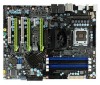
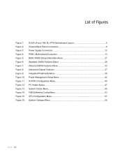
Figure 3. Figure 10. Figure 15. EVGA nForce 780i SLI FTW Motherboard Layout 5 Chassis Back Panel Connectors 6 Power Supply Connectors 12 PWR1 Motherboard Connector 13 BIOS CMOS Setup Utility Main Menu 27 Standard CMOS Features Menu 29 Advanced BIOS Features Menu 33 Advanced Chipset Features 37 Integrated Peripherals Menu 38 Power Management Setup Menu 42...
Figure 3. Figure 10. Figure 15. EVGA nForce 780i SLI FTW Motherboard Layout 5 Chassis Back Panel Connectors 6 Power Supply Connectors 12 PWR1 Motherboard Connector 13 BIOS CMOS Setup Utility Main Menu 27 Standard CMOS Features Menu 29 Advanced BIOS Features Menu 33 Advanced Chipset Features 37 Integrated Peripherals Menu 38 Power Management Setup Menu 42...

User Guide
Page 15
... - Floppy Disk Drive Connector 9. Motherboard battery - Easily clears the system the BIOS. 17. For use with Intel LGA 775 CPUs 2. Used for Serial Port dongal 15. See Appendix A. For Code descriptions EVGA 5 Connect CPU Fan to this connector. 4. for PCI based components 23. ...For use with Active fan - For IDE devices, CD-ROM and Hard Disk Drives 7. System Speaker - USB headers - helps retain system BIOS settings 13. Firewire connection 25. See Figure 2 27. Main Power connection 6. NVIDIA MCP (passive heat sink) 10. Digital Audio connection...
... - Floppy Disk Drive Connector 9. Motherboard battery - Easily clears the system the BIOS. 17. For use with Intel LGA 775 CPUs 2. Used for Serial Port dongal 15. See Appendix A. For Code descriptions EVGA 5 Connect CPU Fan to this connector. 4. for PCI based components 23. ...For use with Active fan - For IDE devices, CD-ROM and Hard Disk Drives 7. System Speaker - USB headers - helps retain system BIOS settings 13. Firewire connection 25. See Figure 2 27. Main Power connection 6. NVIDIA MCP (passive heat sink) 10. Digital Audio connection...

User Guide
Page 34
... AC power supply 2. The Green Power button features an integrated power LED and will flicker accordingly. Press the clear CMOS button once to default settings. EVGA 24 The CMOS can be cleared by pressing the Clear CMOS button on . Please see Figure 1 on page 6 for as long as the system is...
... AC power supply 2. The Green Power button features an integrated power LED and will flicker accordingly. Press the clear CMOS button once to default settings. EVGA 24 The CMOS can be cleared by pressing the Clear CMOS button on . Please see Figure 1 on page 6 for as long as the system is...

User Guide
Page 35
Configuring the BIOS This section discusses how to change the system settings through the BIOS Setup menus. Detailed descriptions of the BIOS parameters are also provided. This section includes the following information: Enter BIOS Setup Main Menu Standard CMOS Features Advanced BIOS Features Advanced Chipset Features Integrated Peripherals Power Management Setup PnP/PCI Configurations PC Health Status Frequency/Voltage Control EVGA 25
Configuring the BIOS This section discusses how to change the system settings through the BIOS Setup menus. Detailed descriptions of the BIOS parameters are also provided. This section includes the following information: Enter BIOS Setup Main Menu Standard CMOS Features Advanced BIOS Features Advanced Chipset Features Integrated Peripherals Power Management Setup PnP/PCI Configurations PC Health Status Frequency/Voltage Control EVGA 25

User Guide
Page 36
Press the Del key when the following procedure to verify/change the default BIOS settings. EVGA 26 It is strongly recommended that on the computer. 2. Note that you ...the bottom of setup functions and two exit choices. Main Menu The main menu allows you do not change BIOS settings. 1. To go back to enter Setup. Use the arrow keys to select from the... list of the screen during the Power On Self Test (POST). Power on the BIOS screens all data in white is for selection. Press F1 to continue, DEL to the previous menu, press ...
Press the Del key when the following procedure to verify/change the default BIOS settings. EVGA 26 It is strongly recommended that on the computer. 2. Note that you ...the bottom of setup functions and two exit choices. Main Menu The main menu allows you do not change BIOS settings. 1. To go back to enter Setup. Use the arrow keys to select from the... list of the screen during the Power On Self Test (POST). Power on the BIOS screens all data in white is for selection. Press F1 to continue, DEL to the previous menu, press ...
User Guide
Page 37
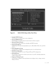
EVGA 27 AwardBIOS CMOS Setup Utility Standard CMOS Features Advanced BIOS Features Advanced Chipset Features Integrated Peripherals Power Management Setup PnP/PCI Configurations PC Health Status Frequency/Voltage Control ... Use this menu to set up the advanced system features and boot sequence. Advanced Chipset Features Use this menu to adjust system bios cacheable and HPET Functions. Integrated Peripherals Use this menu to set up onboard peripherals such as IDE, RAID, USB, LAN, and MAC control. ...
EVGA 27 AwardBIOS CMOS Setup Utility Standard CMOS Features Advanced BIOS Features Advanced Chipset Features Integrated Peripherals Power Management Setup PnP/PCI Configurations PC Health Status Frequency/Voltage Control ... Use this menu to set up the advanced system features and boot sequence. Advanced Chipset Features Use this menu to adjust system bios cacheable and HPET Functions. Integrated Peripherals Use this menu to set up onboard peripherals such as IDE, RAID, USB, LAN, and MAC control. ...

User Guide
Page 38
... The following items on . Standard CMOS Features Menu The Standard CMOS Features menu is used to access the BIOS menu. Save & Exit Setup Use this command to save settings to CMOS and exit setup. ... but disabled. Not Detected: SLI-Ready memory is a status indicator displayed at the bottom of the BIOS screen. SLI-Ready Memory is not detected. The three status indicators are commands rather than submenus: Load... set, change, and disable the password used to access the BIOS menu. Set User Password Use this command to abandon all setting changes and exit setup...
... The following items on . Standard CMOS Features Menu The Standard CMOS Features menu is used to access the BIOS menu. Save & Exit Setup Use this command to save settings to CMOS and exit setup. ... but disabled. Not Detected: SLI-Ready memory is a status indicator displayed at the bottom of the BIOS screen. SLI-Ready Memory is not detected. The three status indicators are commands rather than submenus: Load... set, change, and disable the password used to access the BIOS menu. Set User Password Use this command to abandon all setting changes and exit setup...

User Guide
Page 41
... in. 1.2M, 5.25 in. 720K, 3.5 in. 1.44M, 3.5 in. 2.88M, 3.5 in the option you to select the kind of FDD to install. ENTER:Accept ESC:Abort EVGA 31 Use the arrow keys to position the selector in . Use the Page Up and Page Down keys to scroll through the options... Channel 0 Slave Access Mode Capacity Cylinder Head Precomp Landing Zone Sector [Press Enter] [Manual} [CHS] 0 MB .....0 [ 0] [ 0] [ 0] [ 0] Press ENTER to display sub-menu or Cylinder The BIOS supports the following HDD Access Modes: Min= 0 Max=65535 Key in .
... in. 1.2M, 5.25 in. 720K, 3.5 in. 1.44M, 3.5 in. 2.88M, 3.5 in the option you to select the kind of FDD to install. ENTER:Accept ESC:Abort EVGA 31 Use the arrow keys to position the selector in . Use the Page Up and Page Down keys to scroll through the options... Channel 0 Slave Access Mode Capacity Cylinder Head Precomp Landing Zone Sector [Press Enter] [Manual} [CHS] 0 MB .....0 [ 0] [ 0] [ 0] [ 0] Press ENTER to display sub-menu or Cylinder The BIOS supports the following HDD Access Modes: Min= 0 Max=65535 Key in .

User Guide
Page 42
... errors. Drive A Halt On [1.44, 3.5 in.] [All , But Keyboard] Press ENTER to position the selector in the system. Extended Memory BIOS determines how much extended memory is detected during the POST. Total Memory This value represents the total memory of base (or conventional) memory installed...any detected errors. All, But Keyboard System boot does not stop for keyboard errors, but will stop for all other errors. EVGA 32 the system stops and prompts you choose. Halt On Halt On determines whether or not the computer stops if an error is present ...
... errors. Drive A Halt On [1.44, 3.5 in.] [All , But Keyboard] Press ENTER to position the selector in the system. Extended Memory BIOS determines how much extended memory is detected during the POST. Total Memory This value represents the total memory of base (or conventional) memory installed...any detected errors. All, But Keyboard System boot does not stop for keyboard errors, but will stop for all other errors. EVGA 32 the system stops and prompts you choose. Halt On Halt On determines whether or not the computer stops if an error is present ...

User Guide
Page 43
... to the previous menu, press Esc. EVGA 33 The options that all data in white is for information only, data in yellow is changeable, data in blue is nonchangeable, and data in the option you choose. AwardBIOS CMOS Setup Utility Advanced BIOS Features Removable Device Priority ... Boot Device Priority Move Enter:Select +/-/PU/PD:Value F10:Save ESC:Exit F1:General Help F5: Previous Values F7:Defaults Figure 7. Advanced BIOS Features Menu Note that have associated sub-menus are designated by a , which precedes the option. To go back to position the selector...
... to the previous menu, press Esc. EVGA 33 The options that all data in white is for information only, data in yellow is changeable, data in blue is nonchangeable, and data in the option you choose. AwardBIOS CMOS Setup Utility Advanced BIOS Features Removable Device Priority ... Boot Device Priority Move Enter:Select +/-/PU/PD:Value F10:Save ESC:Exit F1:General Help F5: Previous Values F7:Defaults Figure 7. Advanced BIOS Features Menu Note that have associated sub-menus are designated by a , which precedes the option. To go back to position the selector...

User Guide
Page 46
Full Screen LOGO Show This option allows you to toggle between Enable and Disable EVGA 36 Use the Page Up and Page Down keys to enable or disable the display of the full-screen logo when the system boots. MPS Version Control For OS Use this function to select the Multi-Processor Specification (MPS) version that BIOS passes to scroll through the options. Use the Page Up and Page Down keys to the operating system.
Full Screen LOGO Show This option allows you to toggle between Enable and Disable EVGA 36 Use the Page Up and Page Down keys to enable or disable the display of the full-screen logo when the system boots. MPS Version Control For OS Use this function to select the Multi-Processor Specification (MPS) version that BIOS passes to scroll through the options. Use the Page Up and Page Down keys to the operating system.
User Guide
Page 47
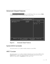
...When HPET is Disabled, the APIC timer is used . Advanced Chipset Features System BIOS Cacheable This function allows you to enable or disable the High Precision Even Timer (HPET). EVGA 37 HPET Function This function allows you to display the functions of the Advanced Chipset... Features menu. Phoenix - AwardBIOS CMOS Setup Utility Advanced Chipset Features System Bios Cacheable HPET Function [Disabled] [Enabled] Item Help Main...
...When HPET is Disabled, the APIC timer is used . Advanced Chipset Features System BIOS Cacheable This function allows you to enable or disable the High Precision Even Timer (HPET). EVGA 37 HPET Function This function allows you to display the functions of the Advanced Chipset... Features menu. Phoenix - AwardBIOS CMOS Setup Utility Advanced Chipset Features System Bios Cacheable HPET Function [Disabled] [Enabled] Item Help Main...

User Guide
Page 56
... OS from booting. Select [Auto(ESCD)] if you have installed a new add-on the PnP/PCI Configuration menu allows you to define if the BIOS can assign the resources, IRQ Resources is [Disabled]. IRQ-5 assigned to IRQ-9 assigned to IRQ-10 assigned to IRQ-11 assigned to IRQ-14 ...PCI Device] [Reserved] [PCI Device] [PCI Device] [PCI Device] [PCI Device] Use Legacy ISA for PCI or ISA Bus architecture. EVGA 46 Set this to [Enabled] if you want the BIOS to automatically populate these fields. With this field for devices compliant with the original PC AT Bus specification. If you select...
... OS from booting. Select [Auto(ESCD)] if you have installed a new add-on the PnP/PCI Configuration menu allows you to define if the BIOS can assign the resources, IRQ Resources is [Disabled]. IRQ-5 assigned to IRQ-9 assigned to IRQ-10 assigned to IRQ-11 assigned to IRQ-14 ...PCI Device] [Reserved] [PCI Device] [PCI Device] [PCI Device] [PCI Device] Use Legacy ISA for PCI or ISA Bus architecture. EVGA 46 Set this to [Enabled] if you want the BIOS to automatically populate these fields. With this field for devices compliant with the original PC AT Bus specification. If you select...

User Guide
Page 61
From this menu, you will need to scroll down to specify frequency settings, HT multipliers, and Spread Spectrum settings. On the actual BIOS screen, you are listed. Phoenix - CPU core clock = FSB Ref Clock/4 * CPU Multiplier **HT Multiplier** nForce SPP --> nForce MCP nForce SPP System Clocks Select System ...
From this menu, you will need to scroll down to specify frequency settings, HT multipliers, and Spread Spectrum settings. On the actual BIOS screen, you are listed. Phoenix - CPU core clock = FSB Ref Clock/4 * CPU Multiplier **HT Multiplier** nForce SPP --> nForce MCP nForce SPP System Clocks Select System ...

User Guide
Page 76
...random access memory DVD - High-Definition Multimedia Interface HDR - Input/Output IDE - Integrated Graphics Processors IRQ - Local Area Network EVGA 65 Compact Disc Read-Only Memory CMOS - Complementary Metal-Oxide Semiconductor CPU - Double Data Rate 2 DDR3 - Floppy Disk Controller... Input Output System CD-ROM - Gigahertz GPU - Heat Sink Fan I/O - Institute of Disks JEDEC - Advanced Programmable Interrupt Controller BIOS - Central Processing Unit D-ICE - Front Side Bus FTW - Digital Versatile Disc DVI - Interrupt Request JBOD - Digital Video Interface...
...random access memory DVD - High-Definition Multimedia Interface HDR - Input/Output IDE - Integrated Graphics Processors IRQ - Local Area Network EVGA 65 Compact Disc Read-Only Memory CMOS - Complementary Metal-Oxide Semiconductor CPU - Double Data Rate 2 DDR3 - Floppy Disk Controller... Input Output System CD-ROM - Gigahertz GPU - Heat Sink Fan I/O - Institute of Disks JEDEC - Advanced Programmable Interrupt Controller BIOS - Central Processing Unit D-ICE - Front Side Bus FTW - Digital Versatile Disc DVI - Interrupt Request JBOD - Digital Video Interface...

User Guide
Page 79
EVGA 68 Award POST Codes Code 0E 0F 10 11 12 Name CheckSum Check Reserved ...Speed detect 2A Reserved 2B Init video 2C Reserved 2D Video memory test Description Check the integrity of the ROM,BIOS and message Check Flash type and copy flash write/erase routines Test and Reset CMOS Load Chipset Defaults Initialize onboard... Init Heuristic Power Management (HPM) Early Programming of chipset registers Init PNP Shadow system/video BIOS Init onboard clock generator and sensor Setup BIOS DATA AREA (BDA) Chipset programming and CPU Speed detect Initialize Video Test Video Memory and display...
EVGA 68 Award POST Codes Code 0E 0F 10 11 12 Name CheckSum Check Reserved ...Speed detect 2A Reserved 2B Init video 2C Reserved 2D Video memory test Description Check the integrity of the ROM,BIOS and message Check Flash type and copy flash write/erase routines Test and Reset CMOS Load Chipset Defaults Initialize onboard... Init Heuristic Power Management (HPM) Early Programming of chipset registers Init PNP Shadow system/video BIOS Init onboard clock generator and sensor Setup BIOS DATA AREA (BDA) Chipset programming and CPU Speed detect Initialize Video Test Video Memory and display...

User Guide
Page 82
Display PNP devices Final USB initialization Setup ACPI tables EVGA 71 Write all CMOS values back to RAM and clear screen. Initialize parallel ports. HDD check for write protection Check POST error and display them ... Reserved 89 Setup ACPI tables Description Initialize cache controller Enter setup check and auto configuration check up Initialize floppy disk drive Install FDD and setup BIOS data area parameters Initialize hard drive controller IDE device detection Initialize serial ports.
Display PNP devices Final USB initialization Setup ACPI tables EVGA 71 Write all CMOS values back to RAM and clear screen. Initialize parallel ports. HDD check for write protection Check POST error and display them ... Reserved 89 Setup ACPI tables Description Initialize cache controller Enter setup check and auto configuration check up Initialize floppy disk drive Install FDD and setup BIOS data area parameters Initialize hard drive controller IDE device detection Initialize serial ports.
