
User Guide
Page 5
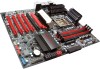
As always this board comes with native support for SATA III/6G for purchasing the EVGA Z68/P67 Motherboard. This board is based off of the new Intel Z68/P67 chipset with the added bonus of EVGA's industry leading 24/7 technical support in case you need it. EVGA Z68/P67 Motherboard Thank you for the performance you demand, delivered when you ever have any issues or questions.
As always this board comes with native support for SATA III/6G for purchasing the EVGA Z68/P67 Motherboard. This board is based off of the new Intel Z68/P67 chipset with the added bonus of EVGA's industry leading 24/7 technical support in case you need it. EVGA Z68/P67 Motherboard Thank you for the performance you demand, delivered when you ever have any issues or questions.

User Guide
Page 6
... Hard Disk Drive may already have purchased all the necessary parts needed to allow for the processor PCI Express Graphics Card Power Supply EVGA assumes you with the motherboard and all the hardware necessary to install and connect your new EVGA Z68/P67 Motherboard. When replacing a motherboard in a PC case, you will need many of the cables. If however, you are building a PC, you will use most of supported CPU's on this motherboard...
... Hard Disk Drive may already have purchased all the necessary parts needed to allow for the processor PCI Express Graphics Card Power Supply EVGA assumes you with the motherboard and all the hardware necessary to install and connect your new EVGA Z68/P67 Motherboard. When replacing a motherboard in a PC case, you will need many of the cables. If however, you are building a PC, you will use most of supported CPU's on this motherboard...

User Guide
Page 7
Officially supports up to 5Gbps EVGA Z68/P67 Motherboard Size EATX form factor of DDR3 memory. USB 2.0 Ports Supports hot plug Supports wake-up from S1 and S3 mode Supports USB 2.0 protocol up to a 480 Mbps transmission rate USB 3.0 Ports Backwards compatible USB 2.0 and USB 1.1 support Supports transfer speeds up to 16GBs of 12 inches x 10.3 inches Microprocessor support Intel Socket 1155 Processor Operating systems: Supports Windows XP/Vista/7 32 and 64 bit ...
Officially supports up to 5Gbps EVGA Z68/P67 Motherboard Size EATX form factor of DDR3 memory. USB 2.0 Ports Supports hot plug Supports wake-up from S1 and S3 mode Supports USB 2.0 protocol up to a 480 Mbps transmission rate USB 3.0 Ports Backwards compatible USB 2.0 and USB 1.1 support Supports transfer speeds up to 16GBs of 12 inches x 10.3 inches Microprocessor support Intel Socket 1155 Processor Operating systems: Supports Windows XP/Vista/7 32 and 64 bit ...
User Guide
Page 8
.../P67 Motherboard SATA ports up to 3.0 Gb/s (300 M/s) data transfer rate SATA ports up to disk - depends on suspend), S3 (suspend to RAM), S4 (Suspend to 6.0 Gb/s (600 M/s) data transfer rate Support for RAID 0, RAID 1, RAID 0+1, RAID5 and RAID 10 ESATA (optional) Onboard LAN Supports 10/100/1000 Mbit/sec Ethernet Onboard IEEE 1394a (Firewire) Supports hot plug Onboard Audio Realtek High-Definition audio Supports 8-channel audio Supports Jack-Sensing function PCI-E Support PCI-E 2.0 Slots Low power...
.../P67 Motherboard SATA ports up to 3.0 Gb/s (300 M/s) data transfer rate SATA ports up to disk - depends on suspend), S3 (suspend to RAM), S4 (Suspend to 6.0 Gb/s (600 M/s) data transfer rate Support for RAID 0, RAID 1, RAID 0+1, RAID5 and RAID 10 ESATA (optional) Onboard LAN Supports 10/100/1000 Mbit/sec Ethernet Onboard IEEE 1394a (Firewire) Supports hot plug Onboard Audio Realtek High-Definition audio Supports 8-channel audio Supports Jack-Sensing function PCI-E Support PCI-E 2.0 Slots Low power...

User Guide
Page 10
... SATA protocol and each one connects a single drive to the motherboard header. - SATA III/6G Data Cables Used to support the SATAIII/6G high speed protocol and each one connects a single drive to the motherboard. - 3-way SLI Bridge (FTW Model Only) Bridges three (3) graphics cards together which allows for 3-way SLI. - 2-way SLI Bridge Bridges two (2) graphics cards together which allows for 2-way SLI. Attaches to IO Shield. - 2-Port SATA Power Cables Allows a Molex power connector to adapt to a SATA power connector. - 2-Port USB...
... SATA protocol and each one connects a single drive to the motherboard header. - SATA III/6G Data Cables Used to support the SATAIII/6G high speed protocol and each one connects a single drive to the motherboard. - 3-way SLI Bridge (FTW Model Only) Bridges three (3) graphics cards together which allows for 3-way SLI. - 2-way SLI Bridge Bridges two (2) graphics cards together which allows for 2-way SLI. Attaches to IO Shield. - 2-Port SATA Power Cables Allows a Molex power connector to adapt to a SATA power connector. - 2-Port USB...

User Guide
Page 11
ECP Panel (Optional) Allows monitoring of post codes and remote control of PCIe slot disable, voltages and CMOS reset all on one bay mounted panel. - EVGA Z68/P67 Motherboard - EVGauge (Optional) Analog Gauge that represents your EVGA Motherboard. Installation CD Contains drivers and soare needed to setup the motherboard. - User Manual Contains Information needed to properly install and configure your CPU frequency in real time. -
ECP Panel (Optional) Allows monitoring of post codes and remote control of PCIe slot disable, voltages and CMOS reset all on one bay mounted panel. - EVGA Z68/P67 Motherboard - EVGauge (Optional) Analog Gauge that represents your EVGA Motherboard. Installation CD Contains drivers and soare needed to setup the motherboard. - User Manual Contains Information needed to properly install and configure your CPU frequency in real time. -
User Guide
Page 17
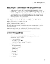
...; Power Connections 24-pin ATX power (PW1) 8-pin ATX 12V power (PW12-1 & PW12-2) Internal Headers Front Panel Header IEEE 1394a Header USB Headers Audio Header SATA II SATA III Chassis Fans USB 2.0 In most cases, it is recommended that the fan assembly is recommended to the fan assembly instruction. 5. Ensure that you through all the necessary connections on the motherboard, it is aligned with the chassis vents according to secure the motherboard using a minimum of a short circuit...
...; Power Connections 24-pin ATX power (PW1) 8-pin ATX 12V power (PW12-1 & PW12-2) Internal Headers Front Panel Header IEEE 1394a Header USB Headers Audio Header SATA II SATA III Chassis Fans USB 2.0 In most cases, it is recommended that the fan assembly is recommended to the fan assembly instruction. 5. Ensure that you through all the necessary connections on the motherboard, it is aligned with the chassis vents according to secure the motherboard using a minimum of a short circuit...

User Guide
Page 18
PW1 Motherboard Connector Table 1. PW1 connector Plug power cable from system power supply to the DIMM slots. Make sure that the power supply cable and pins are properly aligned with the connector on the motherboard. EVGA Z68/P67 Motherboard Expansion slots CMOS Clear Button PW1 is secure. Firmly plug the power supply cable into the connector and make sure it is the main power supply connector located along the edge of the board next to PW1 Board edge Figure 1. PW1 Pin Assignments Connector 24...
PW1 Motherboard Connector Table 1. PW1 connector Plug power cable from system power supply to the DIMM slots. Make sure that the power supply cable and pins are properly aligned with the connector on the motherboard. EVGA Z68/P67 Motherboard Expansion slots CMOS Clear Button PW1 is secure. Firmly plug the power supply cable into the connector and make sure it is the main power supply connector located along the edge of the board next to PW1 Board edge Figure 1. PW1 Pin Assignments Connector 24...
User Guide
Page 19
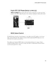
... BIOS chips on the mainboard allows for usage of three completely different bios versions or saving of physical BIOS chips are to be used to provide power to the CPU. The BIOS Select Switch is powered on. EVGA Z68/P67 Motherboard PW12-1 & PW12-2, the 8-pin ATX 12V power connection, is used when the system is located directly to the right of the PC speaker on the lower edge of the mainboard. Align the pins...
... BIOS chips on the mainboard allows for usage of three completely different bios versions or saving of physical BIOS chips are to be used to provide power to the CPU. The BIOS Select Switch is powered on. EVGA Z68/P67 Motherboard PW12-1 & PW12-2, the 8-pin ATX 12V power connection, is used when the system is located directly to the right of the PC speaker on the lower edge of the mainboard. Align the pins...

User Guide
Page 20
... 2.Front Panel Header Pins the power button on the front panel turns the system on and off . The HDD indicator LED indicates the activity status of the hard disks. RESET HD_LED PWRLED RESET PWRSW Pin Signal 1 HD_PWR 3 HD Active 2 PWR LED 4 STBY LED 5 Ground 7 RST BTN 6 PWR BTN 8 Ground Attach the Reset switch cable from the case to these two pins. When the system is off rather than using the onboard button. ...
... 2.Front Panel Header Pins the power button on the front panel turns the system on and off . The HDD indicator LED indicates the activity status of the hard disks. RESET HD_LED PWRLED RESET PWRSW Pin Signal 1 HD_PWR 3 HD Active 2 PWR LED 4 STBY LED 5 Ground 7 RST BTN 6 PWR BTN 8 Ground Attach the Reset switch cable from the case to these two pins. When the system is off rather than using the onboard button. ...

User Guide
Page 26
... Memory slot is functional: This LED is on. STANDBY LED (Blue): When the System is in Standby Mode: This LED is on as long as the motherboard is useful during troubleshooting situations. This Debug LED will remain on . It is receiving constant power. EVGA Z68/P67 Motherboard Provides two-digit POST codes to show why the system may be failing to boot. POWER LED (GREEN) STANDBY LED (BLUE) DIMM LED...
... Memory slot is functional: This LED is on. STANDBY LED (Blue): When the System is in Standby Mode: This LED is on as long as the motherboard is useful during troubleshooting situations. This Debug LED will remain on . It is receiving constant power. EVGA Z68/P67 Motherboard Provides two-digit POST codes to show why the system may be failing to boot. POWER LED (GREEN) STANDBY LED (BLUE) DIMM LED...

User Guide
Page 27
... installing the driver CD that contains utilities, drivers, and additional soare. The CD that has been shipped with a CD that is shipped in the kit. 2. The motherboard supports Windows XP , Vista and Windows 7 both 32 and 64 Bit. The kit comes with the EVGA Z68/P67 Motherboard contains the following software and drivers: Chipset Drivers Audio Drivers RAID Drivers LAN Drivers Matrix Storage USB 3.0 Drivers EVGA E-LEET User's Manual...
... installing the driver CD that contains utilities, drivers, and additional soare. The CD that has been shipped with a CD that is shipped in the kit. 2. The motherboard supports Windows XP , Vista and Windows 7 both 32 and 64 Bit. The kit comes with the EVGA Z68/P67 Motherboard contains the following software and drivers: Chipset Drivers Audio Drivers RAID Drivers LAN Drivers Matrix Storage USB 3.0 Drivers EVGA E-LEET User's Manual...

User Guide
Page 28
... CPU temperatures after microcode loading 0B Cache initialization 0C- Reserved for the EVGA Z68/P67 Motherboard during system boot up. EVGA Z68/P67 Motherboard This section provides the AMI POST Codes (Table 6) for future AMI SEC error codes 0D 0E Microcode not found 0F Microcode not loaded 10 PEI Core is started Debug LED with CPU Temperature Monitor Table 6. Pre-memory North Bridge initialization is started 18 19- Pre-memory CPU initialization is started...
... CPU temperatures after microcode loading 0B Cache initialization 0C- Reserved for the EVGA Z68/P67 Motherboard during system boot up. EVGA Z68/P67 Motherboard This section provides the AMI POST Codes (Table 6) for future AMI SEC error codes 0D 0E Microcode not found 0F Microcode not loaded 10 PEI Core is started Debug LED with CPU Temperature Monitor Table 6. Pre-memory North Bridge initialization is started 18 19- Pre-memory CPU initialization is started...

User Guide
Page 29
.... Boot Strap Processor (BSP) selection 36 CPU post-memory initialization. OEM post memory initialization codes 4E 4F DXE IPL is started 50 Memory initialization error. Serial Presence Detect (SPD) data reading 2C Memory initialization. Post-Memory North Bridge initialization is started 3A 3B- Post-Memory South Bridge initialization is not found or micro-code update Invalid memory size or memory modules do not match. 53 Memory initialization error. System Management Mode (SMM) initialization 37- EVGA Z68/P67 Motherboard...
.... Boot Strap Processor (BSP) selection 36 CPU post-memory initialization. OEM post memory initialization codes 4E 4F DXE IPL is started 50 Memory initialization error. Serial Presence Detect (SPD) data reading 2C Memory initialization. Post-Memory North Bridge initialization is started 3A 3B- Post-Memory South Bridge initialization is not found or micro-code update Invalid memory size or memory modules do not match. 53 Memory initialization error. System Management Mode (SMM) initialization 37- EVGA Z68/P67 Motherboard...

User Guide
Page 30
... user (Forced recovery) F2 Recovery process started Reserved for future AMI error codes FF 60 DXE Core is started F3 Recovery firmware image is not available 5C- CPU DXE initialization is started 67 68 PCI host bridge initialization 69 North Bridge DXE initialization is started 6B- Reserved for future AMI progress codes E7 E8- S3 Resume Failed EB EC- EVGA Z68/P67 Motherboard is failed 5A Internal CPU error 5B reset...
... user (Forced recovery) F2 Recovery process started Reserved for future AMI error codes FF 60 DXE Core is started F3 Recovery firmware image is not available 5C- CPU DXE initialization is started 67 68 PCI host bridge initialization 69 North Bridge DXE initialization is started 6B- Reserved for future AMI progress codes E7 E8- S3 Resume Failed EB EC- EVGA Z68/P67 Motherboard is failed 5A Internal CPU error 5B reset...

User Guide
Page 31
... Boot Device Selection (BDS) phase is started 91 Driver connecting is started 92 PCI Bus initialization is started 93 PCI Bus Hot Plug Controller Initialization 94 PCI Bus Enumeration 95 PCI Bus Request Resources 96 PCI Bus Assign Resources 97 Console Output devices connect 98 Console input devices connect 99 Super IO Initialization 9A USB initialization is started 72 South Bridge devices initialization 73- Reserved for future AMI codes 9F A0 IDE initialization is started A1 IDE Reset A2 IDE Detect A3 IDE Enable...
... Boot Device Selection (BDS) phase is started 91 Driver connecting is started 92 PCI Bus initialization is started 93 PCI Bus Hot Plug Controller Initialization 94 PCI Bus Enumeration 95 PCI Bus Request Resources 96 PCI Bus Assign Resources 97 Console Output devices connect 98 Console input devices connect 99 Super IO Initialization 9A USB initialization is started 72 South Bridge devices initialization 73- Reserved for future AMI codes 9F A0 IDE initialization is started A1 IDE Reset A2 IDE Detect A3 IDE Enable...

User Guide
Page 32
EVGA Z68/P67 Motherboard AD Ready To Boot event AE Legacy Boot event AF Exit Boot Services event B0 Runtime Set Virtual Address MAP Begin B1 Runtime Set Virtual Address MAP End B2 Legacy Option ROM Initialization B3 System Reset B4 USB hot plug B5 PCI bus hot plug B6 Clean-up of NVRAM B7 Configuration Reset (reset of Resources D5 No Space for future AMI codes BF C0- Out of NVRAM settings) B8- Reserved for...
EVGA Z68/P67 Motherboard AD Ready To Boot event AE Legacy Boot event AF Exit Boot Services event B0 Runtime Set Virtual Address MAP Begin B1 Runtime Set Virtual Address MAP End B2 Legacy Option ROM Initialization B3 System Reset B4 USB hot plug B5 PCI bus hot plug B6 Clean-up of NVRAM B7 Configuration Reset (reset of Resources D5 No Space for future AMI codes BF C0- Out of NVRAM settings) B8- Reserved for...

User Guide
Page 34
... Side Bus - Interrupt Request JBOD - Joint Electron Device Engineering Council LAN - Media Access Control MCP - New Technology File System EVGA Z68/P67 Motherboard FSB - High Precision Event Timer HT - Institute of Disks JEDEC - Local Area Network LCD - Liquid Nitrogen Cooling MAC - Native Command Queuing NIC - GHz - Hard Disk Drive HDMI - Integrated Graphics Processors IMC - Integrated memory controller IRQ - Land Grid Array LN2 - Media and Communications Processor MHz - Northbridge NCQ - Network Interface Card NTFS...
... Side Bus - Interrupt Request JBOD - Joint Electron Device Engineering Council LAN - Media Access Control MCP - New Technology File System EVGA Z68/P67 Motherboard FSB - High Precision Event Timer HT - Institute of Disks JEDEC - Local Area Network LCD - Liquid Nitrogen Cooling MAC - Native Command Queuing NIC - GHz - Hard Disk Drive HDMI - Integrated Graphics Processors IMC - Integrated memory controller IRQ - Land Grid Array LN2 - Media and Communications Processor MHz - Northbridge NCQ - Network Interface Card NTFS...

User Guide
Page 35
... SPDIF - Transmission Control Protocol/Internet Protocol USB - Printed Circuit Board PCI - Redundant Array of Inexpensive Disks RGB - Split Frame Rendering SLI - Solid State Drive TCP/IP - Quad Data Rate QPI - Red Green Blue SATA - V-core Voltage Drop VGA - Peripheral Component Interconnect Extended POST - Parallel Advanced Technology Attachment PCB - Universal Serial Bus VDroop - Quick Path Interconnect RAID - Sony/Philips Digital Interconnect Format SPP - System Platform Processors SSD - Serial Advanced Technology Attachment SB - Video Graphics...
... SPDIF - Transmission Control Protocol/Internet Protocol USB - Printed Circuit Board PCI - Redundant Array of Inexpensive Disks RGB - Split Frame Rendering SLI - Solid State Drive TCP/IP - Quad Data Rate QPI - Red Green Blue SATA - V-core Voltage Drop VGA - Peripheral Component Interconnect Extended POST - Parallel Advanced Technology Attachment PCB - Universal Serial Bus VDroop - Quick Path Interconnect RAID - Sony/Philips Digital Interconnect Format SPP - System Platform Processors SSD - Serial Advanced Technology Attachment SB - Video Graphics...

User Guide
Page 36
... a result of shielded cables for a particular purpose. Legal Information All material including but not limited to, text, data, design specifications, diagnostics, graphics, logos, reference boards, files, images, drawings, and soare including this device must be immediately returned to EVGA and the Original Purchaser shall be accurate and reliable. However, EVGA Corporation assumes no warranties, whether express or implied, statutory...
... a result of shielded cables for a particular purpose. Legal Information All material including but not limited to, text, data, design specifications, diagnostics, graphics, logos, reference boards, files, images, drawings, and soare including this device must be immediately returned to EVGA and the Original Purchaser shall be accurate and reliable. However, EVGA Corporation assumes no warranties, whether express or implied, statutory...


