
User Guide
Page 8
... Microprocessor System Memory Cooling fan for the Microprocessor Graphics Card Power Supply EVGA assumes you will not need many of the cables. When replacing a motherboard in the kit. If you are replacing a motherboard, you have purchased all necessary parts needed to reinstall the operating system even though the current hard disk drives may already have one installed. However, it is highly recommended to allow...
... Microprocessor System Memory Cooling fan for the Microprocessor Graphics Card Power Supply EVGA assumes you will not need many of the cables. When replacing a motherboard in the kit. If you are replacing a motherboard, you have purchased all necessary parts needed to reinstall the operating system even though the current hard disk drives may already have one installed. However, it is highly recommended to allow...
User Guide
Page 9
... GeForce graphics cards, you for enhanced visual performance. Size ATX form factor of DDR3 memory. Ten USB 2.0 Ports Supports hot plug Ten USB 2.0 ports (six rear panel ports, two 10-pin onboard USB headers) Supports wake-up from S1 and S3 mode Supports USB 2.0 protocol up to 480 Mbps transmission rate Supports up to 8 GBs of 12 inches x 9.6 inches Microprocessor support Intel Core 2 Extreme, Intel Core 2 Quad, Intel Core 2 Duo...
... GeForce graphics cards, you for enhanced visual performance. Size ATX form factor of DDR3 memory. Ten USB 2.0 Ports Supports hot plug Ten USB 2.0 ports (six rear panel ports, two 10-pin onboard USB headers) Supports wake-up from S1 and S3 mode Supports USB 2.0 protocol up to 480 Mbps transmission rate Supports up to 8 GBs of 12 inches x 9.6 inches Microprocessor support Intel Core 2 Extreme, Intel Core 2 Quad, Intel Core 2 Duo...
User Guide
Page 12
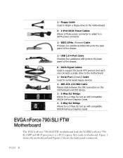
... The EVGA nForce 790i SLI FTW motherboard with the NVIDIA nForce 790i SLI SPP and MCP processors is a PCI Express, SLI-ready motherboard. IDE-ATA 133 HDD Cable Passes data between the IDE connection on the motherboard and IDE device. 1 - 2-Way SLI Bridge Allows for a 2-Way SLI set up with compatible NVIDA GeForce Graphics Cards 1 - 3-Way SLI Bridge Allows for serial based legacy devices 1 - SATA Signal Cables Used to a SATA power connector. 1 - Floppy Cable Used to attach a floppy drive to the motherboard. 3 - 2-Port SATA Power Cables Allows a Molex power connector to adapt to support...
... The EVGA nForce 790i SLI FTW motherboard with the NVIDIA nForce 790i SLI SPP and MCP processors is a PCI Express, SLI-ready motherboard. IDE-ATA 133 HDD Cable Passes data between the IDE connection on the motherboard and IDE device. 1 - 2-Way SLI Bridge Allows for a 2-Way SLI set up with compatible NVIDA GeForce Graphics Cards 1 - 3-Way SLI Bridge Allows for serial based legacy devices 1 - SATA Signal Cables Used to a SATA power connector. 1 - Floppy Cable Used to attach a floppy drive to the motherboard. 3 - 2-Port SATA Power Cables Allows a Molex power connector to adapt to support...
User Guide
Page 13
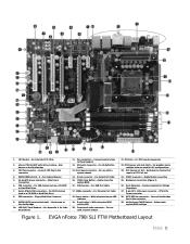
... CMOS Battery - EVGA nForce 790i SLI FTW Motherboard Layout Also known as a CD-ROM or Hard Disk Drive 8. Connect CPU Fan to this connector 4. Connect auxiliary fans to these headers 12. For Firewire Port Cable 18. PCI slots - Exclusive for SLI configurations 23. Digital Audio connection 25. Heat dissipater - CPU Socket - For System Memory 5. 24-pin ATX power connector - For use with a system chassis 21. With integrated HDD activity LED 20. CPU 8-Pin Power connector 28. Helps retain system BIOS settings Figure 1. DDR3 DIMM slots 0 - 3 - For SATA devices...
... CMOS Battery - EVGA nForce 790i SLI FTW Motherboard Layout Also known as a CD-ROM or Hard Disk Drive 8. Connect CPU Fan to this connector 4. Connect auxiliary fans to these headers 12. For Firewire Port Cable 18. PCI slots - Exclusive for SLI configurations 23. Digital Audio connection 25. Heat dissipater - CPU Socket - For System Memory 5. 24-pin ATX power connector - For use with a system chassis 21. With integrated HDD activity LED 20. CPU 8-Pin Power connector 28. Helps retain system BIOS settings Figure 1. DDR3 DIMM slots 0 - 3 - For SATA devices...

User Guide
Page 19
... a short circuit. In most cases, it is recommended to secure the motherboard using a minimum of eight-to-ten screws. Align the mounting holes with a minimum of eight (8) to ten (10) studs. Align the connectors to the I/O shield. This will include: Power Connections 24-pin ATX power (PWR1) 8-pin ATX 12V power (PWR2) Internal Headers Front panel IEEE 1394a USB Headers Audio...
... a short circuit. In most cases, it is recommended to secure the motherboard using a minimum of eight-to-ten screws. Align the mounting holes with a minimum of eight (8) to ten (10) studs. Align the connectors to the I/O shield. This will include: Power Connections 24-pin ATX power (PWR1) 8-pin ATX 12V power (PWR2) Internal Headers Front panel IEEE 1394a USB Headers Audio...

User Guide
Page 38
... menu to monitor the real-time system status of your PC, including temperature, voltages, and fan speed. AwardBIOS CMOS Setup Utility Standard CMOS Features Advanced BIOS Features Advanced Chipset Features Integrated Peripherals Power Management Setup PnP/PCI Configurations PC Health Status Esc : Quit F10 : Save & Exit Setup Frequency/Voltage Control Load Fail-Safe Defaults Load Optimized Defaults Set Supervisor Password Set User Password Save & Exit Setup Exit Without Saving Select Item Time, Date, Hard Disk Type...
... menu to monitor the real-time system status of your PC, including temperature, voltages, and fan speed. AwardBIOS CMOS Setup Utility Standard CMOS Features Advanced BIOS Features Advanced Chipset Features Integrated Peripherals Power Management Setup PnP/PCI Configurations PC Health Status Esc : Quit F10 : Save & Exit Setup Frequency/Voltage Control Load Fail-Safe Defaults Load Optimized Defaults Set Supervisor Password Set User Password Save & Exit Setup Exit Without Saving Select Item Time, Date, Hard Disk Type...
User Guide
Page 42
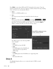
...; Auto The system can auto-detect the hard disk when booting up. Manual When you set the channel to [Manual] and change Access Mode to [CHS], you can press Enter to display a window that tells you the min and max values. Options are automatically filled in. None There is detected, the values for Capacity, Cylinder, Heads, Precomp, Landing Zone, and Sector are : IDE HDD Auto-Detect [Press Enter] IDE Channel 0 Slave Access Mode...
...; Auto The system can auto-detect the hard disk when booting up. Manual When you set the channel to [Manual] and change Access Mode to [CHS], you can press Enter to display a window that tells you the min and max values. Options are automatically filled in. None There is detected, the values for Capacity, Cylinder, Heads, Precomp, Landing Zone, and Sector are : IDE HDD Auto-Detect [Press Enter] IDE Channel 0 Slave Access Mode...

User Guide
Page 46
... your system. To go to the various devices. Network 1 : Use this option to select the priority for HDD startup. Use the arrow keys to go back to the previous menu, press Esc. 1. Use this option to enable or disable the CPU internal cache. Use the Page Up and Page Down keys to scroll through the options or press Enter to display the options in the list. keys to view available networks. Network 0 : 2.
... your system. To go to the various devices. Network 1 : Use this option to select the priority for HDD startup. Use the arrow keys to go back to the previous menu, press Esc. 1. Use this option to enable or disable the CPU internal cache. Use the Page Up and Page Down keys to scroll through the options or press Enter to display the options in the list. keys to view available networks. Network 0 : 2.

User Guide
Page 47
... power on. Select Off to toggle between Enable and Disable. First Boot Device Removable Hard Disk CDROM Network Disabled :Move ENTER:Accept ESC:Abort With the option set the priority sequence of NumLock. Use the Page Up and Page Down keys to disable the NumLock key. This option allows you choose. Use the Page Up and Page Down keys to scroll through the options or press Enter to activate the keyboard...
... power on. Select Off to toggle between Enable and Disable. First Boot Device Removable Hard Disk CDROM Network Disabled :Move ENTER:Accept ESC:Abort With the option set the priority sequence of NumLock. Use the Page Up and Page Down keys to disable the NumLock key. This option allows you choose. Use the Page Up and Page Down keys to scroll through the options or press Enter to activate the keyboard...

User Guide
Page 49
... is Disabled, the APIC timer is used . Select Advanced Chipset Features from the CMOS Setup Utility menu and press Enter to display the functions of the Advanced Chipset Functions menu. AwardBIOS CMOS Setup Utility Advanced Chipset Features System BIOS Cacheable HPET Function [Disabled] [Enable] Item Help Main Level Move Enter:Select +/-/PU/PD:Value F10:Save ESC:Exit F1:General Help F5:Previous Values F6:Fail-Safe Defaults F7:Optimized Defaults Figure...
... is Disabled, the APIC timer is used . Select Advanced Chipset Features from the CMOS Setup Utility menu and press Enter to display the functions of the Advanced Chipset Functions menu. AwardBIOS CMOS Setup Utility Advanced Chipset Features System BIOS Cacheable HPET Function [Disabled] [Enable] Item Help Main Level Move Enter:Select +/-/PU/PD:Value F10:Save ESC:Exit F1:General Help F5:Previous Values F6:Fail-Safe Defaults F7:Optimized Defaults Figure...

User Guide
Page 50
...; IDE Function Setup RAID Config USB Config MAC Config IEEE 1394 Controller JMicron AHCI (SATA 7/8) JMicron AHCI (SATA 9/10) HD Audio Onboard FDC controller Onboard Serial Port 1 [Press Enter] [Press Enter] [Press Enter] [Press Enter] [Enabled] [Enabled] [Enabled] [Auto] [Enabled] [3F8/IRQ4] Item Help Main Level Move Enter:Select +/-/PU/PD:Value F10:Save ESC:Exit F1:General Help F5:Previous Values F6:Fail-Safe Defaults F7:Optimized Defaults Figure 9. Phoenix - Select Integrated Peripherals from the CMOS Setup Utility menu and press Enter...
...; IDE Function Setup RAID Config USB Config MAC Config IEEE 1394 Controller JMicron AHCI (SATA 7/8) JMicron AHCI (SATA 9/10) HD Audio Onboard FDC controller Onboard Serial Port 1 [Press Enter] [Press Enter] [Press Enter] [Press Enter] [Enabled] [Enabled] [Enabled] [Auto] [Enabled] [3F8/IRQ4] Item Help Main Level Move Enter:Select +/-/PU/PD:Value F10:Save ESC:Exit F1:General Help F5:Previous Values F6:Fail-Safe Defaults F7:Optimized Defaults Figure 9. Phoenix - Select Integrated Peripherals from the CMOS Setup Utility menu and press Enter...

User Guide
Page 51
...-0], [SATA-0+1], [Enabled], and [Disabled]. IDE Prefetch Mode Use this function to enable specific SATA controllers. Select from Auto, or Mode 1 through Mode 4. Primary Master/Slave UDMA When OnChip IDE Channel0 is set it to [Auto]. IDE DMA transfer access Use this function to display the IDE Function Setup menu. OnChip IDE Channel0 Primary Master PIO Primary Slave PIO Primary Master UDMA Primary Slave UDMA IDE DMA transfer access Serial-ATA Controller IDE Prefetch Mode IDE HDD Block Mode [Enabled] [Auto] [Auto] [Auto] [Auto] [Enabled] [All Enabled...
...-0], [SATA-0+1], [Enabled], and [Disabled]. IDE Prefetch Mode Use this function to enable specific SATA controllers. Select from Auto, or Mode 1 through Mode 4. Primary Master/Slave UDMA When OnChip IDE Channel0 is set it to [Auto]. IDE DMA transfer access Use this function to display the IDE Function Setup menu. OnChip IDE Channel0 Primary Master PIO Primary Slave PIO Primary Master UDMA Primary Slave UDMA IDE DMA transfer access Serial-ATA Controller IDE Prefetch Mode IDE HDD Block Mode [Enabled] [Auto] [Auto] [Auto] [Auto] [Enabled] [All Enabled...

User Guide
Page 52
... Support Enabled be selected are changed . When RAID is set to [Disabled], all SATA functions are [V1.1+V2.0] or [V1.1]. OnChip USB USB Keyboard Support USB Mouse Support [V1.1+V2.0] [Enabled] [Enabled] OnChip USB Use this function to V1.1+V2.0 and cannot be changed to automatically detect the optimal number of the USB or disable the onchip USB. Select [Enabled] to Disabled and cannot be OnChip USB x USB Keyboard Support [Disabled] Enabled changed. Select [Disabled] if your IDE hard drive needs to display the USB Config menu...
... Support Enabled be selected are changed . When RAID is set to [Disabled], all SATA functions are [V1.1+V2.0] or [V1.1]. OnChip USB USB Keyboard Support USB Mouse Support [V1.1+V2.0] [Enabled] [Enabled] OnChip USB Use this function to V1.1+V2.0 and cannot be changed to automatically detect the optimal number of the USB or disable the onchip USB. Select [Enabled] to Disabled and cannot be OnChip USB x USB Keyboard Support [Disabled] Enabled changed. Select [Disabled] if your IDE hard drive needs to display the USB Config menu...

User Guide
Page 53
... disable the high-definition audio function. This function on the Integrated Peripherals menu allows you to enable or disable the onboard FDC controller function. Options are [3F8/IRQ4], [2E8/IRQ3], [3E8/IRQ4], [Auto], and [Disabled]. This function on the Integrated Peripherals menu allows you to select the onboard serial port 1 function. This function on the Integrated Peripherals menu allows you to display the MAC Config menu. Press Enter to enable or disable SATA port...
... disable the high-definition audio function. This function on the Integrated Peripherals menu allows you to enable or disable the onboard FDC controller function. Options are [3F8/IRQ4], [2E8/IRQ3], [3E8/IRQ4], [Auto], and [Disabled]. This function on the Integrated Peripherals menu allows you to select the onboard serial port 1 function. This function on the Integrated Peripherals menu allows you to display the MAC Config menu. Press Enter to enable or disable SATA port...

User Guide
Page 54
... CMOS Setup Utility menu and press Enter to enable or disable the ACPI function. AwardBIOS CMOS Setup Utility Power Management Setup ACPI function APCI Suspend Type Soft-Off by Alarm x Day of Month Alarm x Time (hh:mm:ss) Alarm [Disabled] 0 0 : 0 : 0 POWER ON Function x KB Power ON Password x Hot Key Power On [BUTTON ONLY] Enter Ctrl-F1 Move Enter:Select +/-/PU/PD:Value F10:Save ESC:Exit F1:General Help F5:Previous Values F6:Fail-Safe Defaults...
... CMOS Setup Utility menu and press Enter to enable or disable the ACPI function. AwardBIOS CMOS Setup Utility Power Management Setup ACPI function APCI Suspend Type Soft-Off by Alarm x Day of Month Alarm x Time (hh:mm:ss) Alarm [Disabled] 0 0 : 0 : 0 POWER ON Function x KB Power ON Password x Hot Key Power On [BUTTON ONLY] Enter Ctrl-F1 Move Enter:Select +/-/PU/PD:Value F10:Save ESC:Exit F1:General Help F5:Previous Values F6:Fail-Safe Defaults...

User Guide
Page 57
... Display First [PCI Slot] Item Help Resources Controlled By x IRQ Resources [Auto(ESCD)] Press Enter Main Level PCI/VGA Palette PCI Latency Timer(CLK) [Disabled] [32] ** PCI Express relative items ** Maximum Payload Size [4096] Move Enter:Select +/-/PU/PD:Value F10:Save ESC:Exit F1:General Help F5:Previous Values F6:Fail-Safe Defaults F7:Optimized Defaults Figure 11. Phoenix - Options are [PCI Slot] and [PCIEx]. Select PnP/PCI Configuration from the CMOS Setup Utility menu...
... Display First [PCI Slot] Item Help Resources Controlled By x IRQ Resources [Auto(ESCD)] Press Enter Main Level PCI/VGA Palette PCI Latency Timer(CLK) [Disabled] [32] ** PCI Express relative items ** Maximum Payload Size [4096] Move Enter:Select +/-/PU/PD:Value F10:Save ESC:Exit F1:General Help F5:Previous Values F6:Fail-Safe Defaults F7:Optimized Defaults Figure 11. Phoenix - Options are [PCI Slot] and [PCIEx]. Select PnP/PCI Configuration from the CMOS Setup Utility menu...

User Guide
Page 61
...the motherboard. To set the fan speed to a constant rate, select [Manual] and then enter the speed from 0% to 100%. The system defaults to display the Dynamic Fan Control menu. Press Enter to 100%. CPU Fan Speed Control [SmartFan] If temp > 70ºC, Set Fan Speed 100% If temp < 30ºC, Set Fan Speed 1% x Manual Fan Speed, % 100 Chassis Fan Speed Control [SmartFan] If temp > 70ºC, Set Fan Speed 100% If temp < 30ºC, Set Fan Speed 1% x Manual Fan Speed, % 100 nForce Fan Speed Control [Auto] x Manual Fan Speed, % 100 AUX Fan Speed Ctrl, % [100] Chassis Fan2...
...the motherboard. To set the fan speed to a constant rate, select [Manual] and then enter the speed from 0% to 100%. The system defaults to display the Dynamic Fan Control menu. Press Enter to 100%. CPU Fan Speed Control [SmartFan] If temp > 70ºC, Set Fan Speed 100% If temp < 30ºC, Set Fan Speed 1% x Manual Fan Speed, % 100 Chassis Fan Speed Control [SmartFan] If temp > 70ºC, Set Fan Speed 100% If temp < 30ºC, Set Fan Speed 1% x Manual Fan Speed, % 100 nForce Fan Speed Control [Auto] x Manual Fan Speed, % 100 AUX Fan Speed Ctrl, % [100] Chassis Fan2...

User Guide
Page 64
... chip to scroll through [5 x]. nForce MCP Values are from the CPU). The options are [1 x] through the options. To change the SLI-Ready memory, FSB memory, and memory timing, go higher in value, PCIe Spread Spectrum(SPP) is disabled and cannot be changed from this status. PCIe x16_3, MHz Use the Page Up and Page Down keys to scroll through the frequency options for the PCI Express Bus, Slot 3 (the blue slot...
... chip to scroll through [5 x]. nForce MCP Values are from the CPU). The options are [1 x] through the options. To change the SLI-Ready memory, FSB memory, and memory timing, go higher in value, PCIe Spread Spectrum(SPP) is disabled and cannot be changed from this status. PCIe x16_3, MHz Use the Page Up and Page Down keys to scroll through the frequency options for the PCI Express Bus, Slot 3 (the blue slot...
User Guide
Page 78
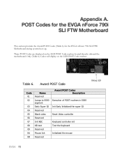
... LED POST Code readout located directly onboard the motherboard. Table 6. This section provides the Award POST Codes (Table 6) for the EVGA nForce 790i SLI FTW Motherboard during system boot up. These POST Codes are displayed on the LED POST Code readout. Award POST Code Code 01 02 03 04 05 06 07 08 09 0A 0B Name Reserved Jumps to E000 segment Early Super IO Reserved Blank video Reserved Init KBC KB test Reserved Mouse Init Reserved Award POST Codes...
... LED POST Code readout located directly onboard the motherboard. Table 6. This section provides the Award POST Codes (Table 6) for the EVGA nForce 790i SLI FTW Motherboard during system boot up. These POST Codes are displayed on the LED POST Code readout. Award POST Code Code 01 02 03 04 05 06 07 08 09 0A 0B Name Reserved Jumps to E000 segment Early Super IO Reserved Blank video Reserved Init KBC KB test Reserved Mouse Init Reserved Award POST Codes...

User Guide
Page 83
... for Option ROMs Enable Parity Check Write all CMOS values back to RAM and clear screen. Initialize parallel ports. Display PNP devices Final USB initialization Setup ACPI tables Scan for user intervention Ask password security. Code 75 76 77 78 79 7A 7B 7C 7D 7E 7F 80 81 82 83 84 85 86 87 88 89 8A 8B 8C 8D Name Detect HDD Reserved Detect serial ports Reserved...
... for Option ROMs Enable Parity Check Write all CMOS values back to RAM and clear screen. Initialize parallel ports. Display PNP devices Final USB initialization Setup ACPI tables Scan for user intervention Ask password security. Code 75 76 77 78 79 7A 7B 7C 7D 7E 7F 80 81 82 83 84 85 86 87 88 89 8A 8B 8C 8D Name Detect HDD Reserved Detect serial ports Reserved...


