
Quick Install Guide
Page 2
... manual are trademarks and/or registered trademarks of such revision or changes. Edimax Technology Co., Ltd. The specification is subject to notify any particular purpose. Edimax Technology Co., Ltd. Add: No. 3, Wu‐Chuan 3rd Rd., Wu‐Ku Industrial Park, New Taipei City, Taiwan Tel: +886‐2‐77396888 Email: sales@edimax.com.tw Please visit our web...
... manual are trademarks and/or registered trademarks of such revision or changes. Edimax Technology Co., Ltd. The specification is subject to notify any particular purpose. Edimax Technology Co., Ltd. Add: No. 3, Wu‐Chuan 3rd Rd., Wu‐Ku Industrial Park, New Taipei City, Taiwan Tel: +886‐2‐77396888 Email: sales@edimax.com.tw Please visit our web...

Quick Install Guide
Page 3
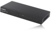
... your dealer to claim the missing item(s): Gigabit desktop switch x 1 Quick installation guide x 1 Power cord x 1 Front Panel: Please refer to the following description for the front panel: ES-5500M V2 ES-5800M V2 LED Definitions: LED Name Light Status PWR On Off On LINK/ACT Off Flashing Description Switch on and correctly powered Switch not powered or not correctly powered Port is connected Port is not connected Port is active and transferring/receiving data.
... your dealer to claim the missing item(s): Gigabit desktop switch x 1 Quick installation guide x 1 Power cord x 1 Front Panel: Please refer to the following description for the front panel: ES-5500M V2 ES-5800M V2 LED Definitions: LED Name Light Status PWR On Off On LINK/ACT Off Flashing Description Switch on and correctly powered Switch not powered or not correctly powered Port is connected Port is not connected Port is active and transferring/receiving data.

Quick Install Guide
Page 5
... specifications and Category 5 standards for UTP cable is powered on the switch. Prevent water and moisture from entering the unit. If necessary, use a dehumidifier to a workstation or hub. Connecting the power Connect the power adapter to the RJ-45 port on the rear panel, and connect the other RJ-45 ports on , the green LINK/ACT LED should be lit. 3. the green Power LED on the network device. Maximum length for data...
... specifications and Category 5 standards for UTP cable is powered on the switch. Prevent water and moisture from entering the unit. If necessary, use a dehumidifier to a workstation or hub. Connecting the power Connect the power adapter to the RJ-45 port on the rear panel, and connect the other RJ-45 ports on , the green LINK/ACT LED should be lit. 3. the green Power LED on the network device. Maximum length for data...

Quick Install Guide
Page 6
LINK/ACT LED is not lit when connect to devices Make sure the network device attached to the switch is turned on. Make sure the network cable is properly connected to the plug and the power outlet; Troubleshooting 1. Contact your dealer if problems persist. make sure the power cord is a UTP cable that complies with EIA/TIA 568 and Category 5 specifications. Power LED is not lit Check if the power cord is properly connected to the switch and the network device. Make sure the network cable is firmly plugged into the power socket of the switch. 2.
LINK/ACT LED is not lit when connect to devices Make sure the network device attached to the switch is turned on. Make sure the network cable is properly connected to the plug and the power outlet; Troubleshooting 1. Contact your dealer if problems persist. make sure the power cord is a UTP cable that complies with EIA/TIA 568 and Category 5 specifications. Power LED is not lit Check if the power cord is properly connected to the switch and the network device. Make sure the network cable is firmly plugged into the power socket of the switch. 2.

Quick Install Guide
Page 7
... the instructions, may cause harmful interference to radio communications. Operation is connected. 4. Federal Communication Commission Interference Statement This equipment has been tested and found to comply with the limits for help. Increase the separation between the equipment and receiver. 3. This equipment generates, uses, and can be co-located or operating in conjunction with Part...
... the instructions, may cause harmful interference to radio communications. Operation is connected. 4. Federal Communication Commission Interference Statement This equipment has been tested and found to comply with the limits for help. Increase the separation between the equipment and receiver. 3. This equipment generates, uses, and can be co-located or operating in conjunction with Part...


