English manual
Page 5
... the overclocking capac- nections might damage the motherboard. ■ When handling the motherboard, avoid touching any installation steps or have a problem related to the use of your CPU is a PCI Express x16 graphics card installed in order to avoid damage to the motherboard and CPU due to unplug the AC power cord from the power supply outlet. Installation Precautions WARNING! Incorrect con- Also, make sure the power supply AC input voltage setting...
... the overclocking capac- nections might damage the motherboard. ■ When handling the motherboard, avoid touching any installation steps or have a problem related to the use of your CPU is a PCI Express x16 graphics card installed in order to avoid damage to the motherboard and CPU due to unplug the AC power cord from the power supply outlet. Installation Precautions WARNING! Incorrect con- Also, make sure the power supply AC input voltage setting...
English manual
Page 9
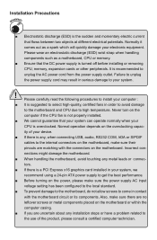
...65533;� Expansion Slots 1 x PCI Express x16 slot 1 x PCI Express x1 slot 2 x PCI slots Onboard Serial ATA 4 x SATA connectors 300MB/s data transfer rate Support hot plug and NCQ (Native Command Queuing ) USB Support hot plug Support up to 10 x USB 2.0 ports (4 rear panel ports, 3 onboard USB headers supporting 6 extra ports) Support USB 2.0 protocol up to 480Mb/s Internal Connectors 1 x 24-pin ATX main power connector 1 x 4-pin ATX 12V power connector 1 x Floppy disk drive connector 1 x IDE connector 4 x SATA connectors 3 x USB 2.0 c��o�...
...65533;� Expansion Slots 1 x PCI Express x16 slot 1 x PCI Express x1 slot 2 x PCI slots Onboard Serial ATA 4 x SATA connectors 300MB/s data transfer rate Support hot plug and NCQ (Native Command Queuing ) USB Support hot plug Support up to 10 x USB 2.0 ports (4 rear panel ports, 3 onboard USB headers supporting 6 extra ports) Support USB 2.0 protocol up to 480Mb/s Internal Connectors 1 x 24-pin ATX main power connector 1 x 4-pin ATX 12V power connector 1 x Floppy disk drive connector 1 x IDE connector 4 x SATA connectors 3 x USB 2.0 c��o�...
English manual
Page 14
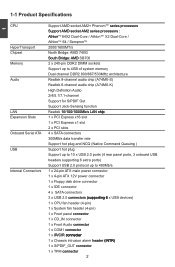
... CPU, memory, power supply, slots, pin headers and the mounting of these modules. Please refer to the motherboard layout prior to any installation and read the contents in this website for more supporting information about CPU, Memory and VGA for your motherboard : http://www.foxconnchannel.com/product/Motherboards/compatibility.aspx This chapter includes the following information : ■ Install the CPU and CPU Cooler ■ Install the Memory ■ Install an Expansion Card ■ Install other Internal Connectors...
... CPU, memory, power supply, slots, pin headers and the mounting of these modules. Please refer to the motherboard layout prior to any installation and read the contents in this website for more supporting information about CPU, Memory and VGA for your motherboard : http://www.foxconnchannel.com/product/Motherboards/compatibility.aspx This chapter includes the following information : ■ Install the CPU and CPU Cooler ■ Install the Memory ■ Install an Expansion Card ■ Install other Internal Connectors...
English manual
Page 19
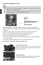
... BIOS Setup to make any required BIOS changes for your expansion card. ■ Always turn off the computer and unplug the power cord from the power outlet before installing an expansion card to release the card and then pull the card straight up from the chassis back panel. 2. Make sure the metal contacts on the card are completely inserted into the PCI Express x16 slot. Installing and Removing a PCI Express x16 Graphics Card : • Installing a Graphics Card...
... BIOS Setup to make any required BIOS changes for your expansion card. ■ Always turn off the computer and unplug the power cord from the power outlet before installing an expansion card to release the card and then pull the card straight up from the chassis back panel. 2. Make sure the metal contacts on the card are completely inserted into the PCI Express x16 slot. Installing and Removing a PCI Express x16 Graphics Card : • Installing a Graphics Card...
English manual
Page 21
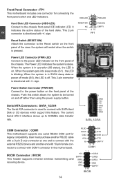
Hard Disk LED Connector (HDD-LED) Connect to the power LED indicator on the front panel of the chassis. This 2-pin connector is pressed. the system will restart when the switch is directional with SATA Hard Disk or CD devices which support this switch allows the system to be turned on and off . sign. Serial ATA Connectors : SATA_1/2/3/4 The Serial ATA connector is blinking; When the system is in operation (S0 status), the LED is on the...
Hard Disk LED Connector (HDD-LED) Connect to the power LED indicator on the front panel of the chassis. This 2-pin connector is pressed. the system will restart when the switch is directional with SATA Hard Disk or CD devices which support this switch allows the system to be turned on and off . sign. Serial ATA Connectors : SATA_1/2/3/4 The Serial ATA connector is blinking; When the system is in operation (S0 status), the LED is on the...
English manual
Page 24
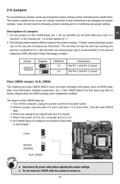
...Jumper: CLR_CMOS The motherboard uses CMOS RAM to modify them . 2 2-5 Jumpers For some features needed, users can change the jumper settings on this motherboard by changing the jumper settings. However, in next chapter. 1 Clear 2 3 WARNING! Remove jumper cap from the power outlet. 2. Users should read the following table explains different types of Jumpers 1. Jumper 1 Diagram 1 1 Definition 1-2 2-3 Description Set Pin 1 and Pin 2 closed Set Pin 2 and Pin 3 closed . 4. For any jumper setting. The steps to factory default when the BIOS settings were mistakenly modified. Plug...
...Jumper: CLR_CMOS The motherboard uses CMOS RAM to modify them . 2 2-5 Jumpers For some features needed, users can change the jumper settings on this motherboard by changing the jumper settings. However, in next chapter. 1 Clear 2 3 WARNING! Remove jumper cap from the power outlet. 2. Users should read the following table explains different types of Jumpers 1. Jumper 1 Diagram 1 1 Definition 1-2 2-3 Description Set Pin 1 and Pin 2 closed Set Pin 2 and Pin 3 closed . 4. For any jumper setting. The steps to factory default when the BIOS settings were mistakenly modified. Plug...
English manual
Page 27
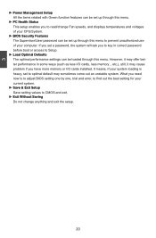
... memory or I /O cards, less memory ...etc.), still, it may cause problem if you set to optimal default may offer better performance in correct password before boot or access to Setup. ► Load Optimal Defaults The optimal performance settings can be loaded through this menu to CMOS and exit. ► Exit Without Saving Do not change Fan speeds, and displays temperatures and voltages of your CPU/System. ► BIOS Security Features The Supervisor/User password can be set...
... memory or I /O cards, less memory ...etc.), still, it may cause problem if you set to optimal default may offer better performance in correct password before boot or access to Setup. ► Load Optimal Defaults The optimal performance settings can be loaded through this menu to CMOS and exit. ► Exit Without Saving Do not change Fan speeds, and displays temperatures and voltages of your CPU/System. ► BIOS Security Features The Supervisor/User password can be set...
English manual
Page 28
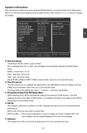
... display information only applies when SATA Mode Select is set to [IDE] mode. ► Halt On This category determines whether or not the computer will not stop if an error is detected during powering up /down keys to select an item, then use [TAB] to move forward a field. CMOS Setup Utility - Year-year, set up the standard BIOS features, such as the date, time, floppy drive and...
... display information only applies when SATA Mode Select is set to [IDE] mode. ► Halt On This category determines whether or not the computer will not stop if an error is detected during powering up /down keys to select an item, then use [TAB] to move forward a field. CMOS Setup Utility - Year-year, set up the standard BIOS features, such as the date, time, floppy drive and...
English manual
Page 32
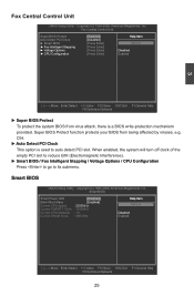
...;z� Options Current FSB/HTT Clock : 1000MHz Current CPU Multiplier : 11x D� isab� led Current DRAM Clock : 266 MHz Enabled Move Enter:Select +/-/:Value F10:Save ESC:Exit F1:General Help F9:Optimized Defaults 25 Smart BIOS Smart Power LED D�is a BIOS write-protection mechanism provided. Copyright (C) 1985-2006, American Megatrends, Inc. CIH. ► Auto Detect PCI Clock This option is used to its submenu. Fox Central Control Unit CMOS Setup Utility -
...;z� Options Current FSB/HTT Clock : 1000MHz Current CPU Multiplier : 11x D� isab� led Current DRAM Clock : 266 MHz Enabled Move Enter:Select +/-/:Value F10:Save ESC:Exit F1:General Help F9:Optimized Defaults 25 Smart BIOS Smart Power LED D�is a BIOS write-protection mechanism provided. Copyright (C) 1985-2006, American Megatrends, Inc. CIH. ► Auto Detect PCI Clock This option is used to its submenu. Fox Central Control Unit CMOS Setup Utility -
English manual
Page 33
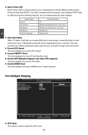
... No CPU Fan No Display No Memory Post Error Message Power LED Status On Blinking once (blinking 0.5 sec., off 0.5 sec.) Blinking once (blinking 2 sec., off 2 sec.) Blinking twice Blinking thrice ► Smart Boot Menu When PC starts, it displays POST state by different long-short blinking intervals. Fox Intelligent Stepping CMOS Setup Utility - Fox Intelligent Stepping CPU Clock 2� 00 H�e� lp�It� e�m PCI Express Clock 1� 00] CPU Multiplier Adjust [Auto...
... No CPU Fan No Display No Memory Post Error Message Power LED Status On Blinking once (blinking 0.5 sec., off 0.5 sec.) Blinking once (blinking 2 sec., off 2 sec.) Blinking twice Blinking thrice ► Smart Boot Menu When PC starts, it displays POST state by different long-short blinking intervals. Fox Intelligent Stepping CMOS Setup Utility - Fox Intelligent Stepping CPU Clock 2� 00 H�e� lp�It� e�m PCI Express Clock 1� 00] CPU Multiplier Adjust [Auto...
English manual
Page 37
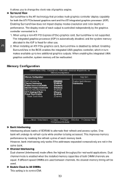
When using a non-ATI PCI Express (PCIe) graphics card, SurroundView is being accessed. Enabling SurroundView in the BIOS enables the integrated UMA graphics controller, which in the same bank. ► Channel Interleaving Dual channel (Interleaved) mode offers the highest throughput for real world applications. Memory Configuration CMOS Setup Utility - If different speed DIMMs are used . ► Enable Clock to All DIMMs This setting is controlled independently by default. When installing an ATI PCIe graphics card, SurroundView is disabled by the graphics controller connected to it. ...
When using a non-ATI PCI Express (PCIe) graphics card, SurroundView is being accessed. Enabling SurroundView in the BIOS enables the integrated UMA graphics controller, which in the same bank. ► Channel Interleaving Dual channel (Interleaved) mode offers the highest throughput for real world applications. Memory Configuration CMOS Setup Utility - If different speed DIMMs are used . ► Enable Clock to All DIMMs This setting is controlled independently by default. When installing an ATI PCIe graphics card, SurroundView is disabled by the graphics controller connected to it. ...
English manual
Page 40
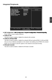
...LAN boot ROM lets you can enable a client PC system on the network. By installing a boot ROM in �g� Press to go to relative submenu. ► OnBoard LAN This item is used to enable or disable the onboard LAN controller. ► OnBoard LAN Boot ROM This item is used to enable or disable the HD Audio Controller. 33 3 Integrated Peripherals CMOS Setup Utility...65533;le�d�] HD Audio Controller [Auto] Help Item Move Enter:Select +/-/:Value F10:Save ESC:Exit F1:General Help F9:Optimized Defaults ► IDE Configuration / U��S�B�...
...LAN boot ROM lets you can enable a client PC system on the network. By installing a boot ROM in �g� Press to go to relative submenu. ► OnBoard LAN This item is used to enable or disable the onboard LAN controller. ► OnBoard LAN Boot ROM This item is used to enable or disable the HD Audio Controller. 33 3 Integrated Peripherals CMOS Setup Utility...65533;le�d�] HD Audio Controller [Auto] Help Item Move Enter:Select +/-/:Value F10:Save ESC:Exit F1:General Help F9:Optimized Defaults ► IDE Configuration / U��S�B�...
English manual
Page 41
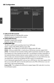
Options : [Native IDE]; [RAID]; [AHCI]; [Legacy IDE]. [Native IDE] - If your motherboard supporting AHCI, and you have a SATA device, which is running for Serial ATA. Copyright (C) 1985-2006, American Megatrends, Inc. This configures the SATA ports to get its specification. The specification includes a description of your SATA drives must also support AHCI. [AHCI] - This configures the SATA ports to set the operating mode of the hardware/software interface between system software and the host controller hardware. IDE Configuration ��ID��E&#...
Options : [Native IDE]; [RAID]; [AHCI]; [Legacy IDE]. [Native IDE] - If your motherboard supporting AHCI, and you have a SATA device, which is running for Serial ATA. Copyright (C) 1985-2006, American Megatrends, Inc. This configures the SATA ports to get its specification. The specification includes a description of your SATA drives must also support AHCI. [AHCI] - This configures the SATA ports to set the operating mode of the hardware/software interface between system software and the host controller hardware. IDE Configuration ��ID��E&#...
English manual
Page 45
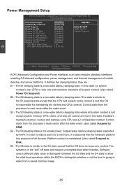
... sleeping state is the lowest power, longest wake latency sleeping state supported by PCI Card [Disabled] System Suspend. The S4 sleeping state is a low wake latency sleeping state where all system context. (also called Suspend to RAM) S4 - Copyright (C) 1985-2006, American Megatrends, Inc. The system is a low wake latency sleeping state. Control starts from the processor's reset vector after the wake event. (also called Suspend to Disk) S5 - Power Management Setup...
... sleeping state is the lowest power, longest wake latency sleeping state supported by PCI Card [Disabled] System Suspend. The S4 sleeping state is a low wake latency sleeping state where all system context. (also called Suspend to RAM) S4 - Copyright (C) 1985-2006, American Megatrends, Inc. The system is a low wake latency sleeping state. Control starts from the processor's reset vector after the wake event. (also called Suspend to Disk) S5 - Power Management Setup...
English manual
Page 47
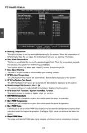
... Status CMOS Setup Utility - Copyright (C) 1985-2006, American Megatrends, Inc. This function works only when your operating system is supporting ACPI. ► Case Open Warning This item is used to enable or disable case open warning function. ► CPU/System Temperature The CPU/System temperature are automatically detected and displayed by the system. ► CPU Fan/System Fan Speed The CPU fan/System fan speed are automatically detected and displayed by the system. ► DRAM Voltage/CPU Core/+ 3.3V...
... Status CMOS Setup Utility - Copyright (C) 1985-2006, American Megatrends, Inc. This function works only when your operating system is supporting ACPI. ► Case Open Warning This item is used to enable or disable case open warning function. ► CPU/System Temperature The CPU/System temperature are automatically detected and displayed by the system. ► CPU Fan/System Fan Speed The CPU fan/System fan speed are automatically detected and displayed by the system. ► DRAM Voltage/CPU Core/+ 3.3V...
English manual
Page 51
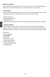
... is set to BIOS. AMD RAID Utility 44 Microsoft DirectX 9.0 F. 4 Utility CD content This motherboard comes with one Utility CD. Realtek LAN Driver D. Software Utilities Use these options to install. 1. You can simply put it into your CD/DVD-ROM drive, and the main menu will be displayed on your system. You should install the drivers in BIOS is a very powerful user interface program which allows you how to install all the drivers have been installed. Realtek HDA Audio Driver C. FOX...
... is set to BIOS. AMD RAID Utility 44 Microsoft DirectX 9.0 F. 4 Utility CD content This motherboard comes with one Utility CD. Realtek LAN Driver D. Software Utilities Use these options to install. 1. You can simply put it into your CD/DVD-ROM drive, and the main menu will be displayed on your system. You should install the drivers in BIOS is a very powerful user interface program which allows you how to install all the drivers have been installed. Realtek HDA Audio Driver C. FOX...
English manual
Page 76
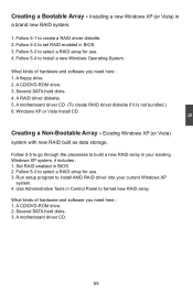
A floppy drive. 2. Several SATA hard disks. 4. Follow 5-5 to go through the processes to select a RAID array for use . 4. Use Administrative Tools in BIOS. 2. A motherboard driver CD. 69 Follow 5-3 to build a new RAID array in your current Windows XP system. 4. Windows XP or Vista Install CD. Creating a Non-Bootable Array - Set RAID enabled in Control Panel to install AMD RAID driver into your existing Windows XP system, it is not bundled.) 6. Run setup program to format new RAID array...
A floppy drive. 2. Several SATA hard disks. 4. Follow 5-5 to go through the processes to select a RAID array for use . 4. Use Administrative Tools in BIOS. 2. A motherboard driver CD. 69 Follow 5-3 to build a new RAID array in your current Windows XP system. 4. Windows XP or Vista Install CD. Creating a Non-Bootable Array - Set RAID enabled in Control Panel to install AMD RAID driver into your existing Windows XP system, it is not bundled.) 6. Run setup program to format new RAID array...
English manual
Page 83
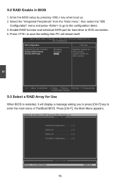
... "Main menu", then select the "IDE Configuration" menu and press to go to Select Option [ESC] Exit 76 Move Enter:Select +/-/:Value F10:Save ESC:Exit F1:General Help F9:Optimized Defaults 5-3 Select a RAID Array for hard drive or DVD connection. 4. 5 5-2 RAID Enable in BIOS 1. Enter the BIOS setup by pressing key when boot up. 2. Enable RAID function and individual SATA port for Use When BIOS is restarted, it will reboot itself. CMOS Setup Utility - IDE Configuration �...
... "Main menu", then select the "IDE Configuration" menu and press to go to Select Option [ESC] Exit 76 Move Enter:Select +/-/:Value F10:Save ESC:Exit F1:General Help F9:Optimized Defaults 5-3 Select a RAID Array for hard drive or DVD connection. 4. 5 5-2 RAID Enable in BIOS 1. Enter the BIOS setup by pressing key when boot up. 2. Enable RAID function and individual SATA port for Use When BIOS is restarted, it will reboot itself. CMOS Setup Utility - IDE Configuration �...
English manual
Page 97
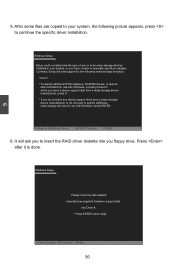
... mass storage devices installed in your system, the following mass storage device(s): * To specify additional SCSI adapters, CD-ROM drivers, or special disk controllers for use with Windows, press ENTER. Currently, Setup will ask you do not want to insert the RAID driver diskette into Drive A: * Press ENTER when ready Enter=Continue ESC=Cancel F3=Exit 90 S=Specify Additional Device ENTER=Continue F3=Exit 6. Windows Setup Please insert the disk labeled manufacturer-supplied hardware support disk...
... mass storage devices installed in your system, the following mass storage device(s): * To specify additional SCSI adapters, CD-ROM drivers, or special disk controllers for use with Windows, press ENTER. Currently, Setup will ask you do not want to insert the RAID driver diskette into Drive A: * Press ENTER when ready Enter=Continue ESC=Cancel F3=Exit 90 S=Specify Additional Device ENTER=Continue F3=Exit 6. Windows Setup Please insert the disk labeled manufacturer-supplied hardware support disk...
English manual
Page 100
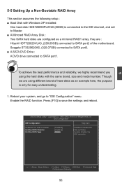
... "IDE Configuration" menu. Copyright (C) 1985-2006, American Megatrends, Inc. CMOS Setup Utility - Though we highly recommend you using different brand of the motherboard. Reboot your system, and go to save the settings and reboot. To achieve the best performance and reliability, we are : Hitachi HDT725025VLA3, (250.05GB) connected to SATA port1. Enable the RAID function. Seagate ST3320620AS, (320.07GB) connected to SATA port3. ■ A SATA DVD Drive : A DVD drive connected to SATA port2...
... "IDE Configuration" menu. Copyright (C) 1985-2006, American Megatrends, Inc. CMOS Setup Utility - Though we highly recommend you using different brand of the motherboard. Reboot your system, and go to save the settings and reboot. To achieve the best performance and reliability, we are : Hitachi HDT725025VLA3, (250.05GB) connected to SATA port1. Enable the RAID function. Seagate ST3320620AS, (320.07GB) connected to SATA port3. ■ A SATA DVD Drive : A DVD drive connected to SATA port2...


