
English Manual
Page 5
... the CPU fan is overclocked. tors. ■ If there is a PCI Express x16 graphics card installed in your device. ■ If there is suggested to select high-quality, certified fans in contact with the connectors on the motherboard or within the computer casing. ■ If you are no leftover screws or metal components placed on the motherboard. Installation Precautions WARNING! Incorrect con- Also, make sure the power supply...
... the CPU fan is overclocked. tors. ■ If there is a PCI Express x16 graphics card installed in your device. ■ If there is suggested to select high-quality, certified fans in contact with the connectors on the motherboard or within the computer casing. ■ If you are no leftover screws or metal components placed on the motherboard. Installation Precautions WARNING! Incorrect con- Also, make sure the power supply...

English Manual
Page 6
... Specifications 2 Layout...4 Back Panel Connectors 5 Chapter 2 Hardware Install Install the CPU and CPU Cooler 8 Install the Memory 10 Install an Expansion Card 12 Install other Internal Connectors 13 Jumpers 17 Install driver and utility 18 Chapter 3 BIOS Setup Enter BIOS Setup 21 Main Menu 21 System Information 23 Advanced BIOS Features 25 Core Releaser 26 Fox Central Control Unit 27 Advanced Chipset Features 32 Integrated Peripherals 36 Power Management Setup 40 PC Health Status 42 BIOS Security Features 43 Load Optimal Defaults 43 Save & Exit Setup...
... Specifications 2 Layout...4 Back Panel Connectors 5 Chapter 2 Hardware Install Install the CPU and CPU Cooler 8 Install the Memory 10 Install an Expansion Card 12 Install other Internal Connectors 13 Jumpers 17 Install driver and utility 18 Chapter 3 BIOS Setup Enter BIOS Setup 21 Main Menu 21 System Information 23 Advanced BIOS Features 25 Core Releaser 26 Fox Central Control Unit 27 Advanced Chipset Features 32 Integrated Peripherals 36 Power Management Setup 40 PC Health Status 42 BIOS Security Features 43 Load Optimal Defaults 43 Save & Exit Setup...
English Manual
Page 14
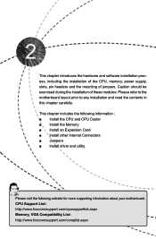
CPU Support List: http://www.foxconnsupport.com/cpusupportlist.aspx Memory, VGA Compatibility List: http://www.foxconnsupport.com/complist.aspx Caution should be exercised during the installation of jumpers. This chapter includes the following information : ■ Install the CPU and CPU Cooler ■ Install the Memory ■ Install an Expansion Card ■ Install other Internal Connectors ■ Jumpers ■ Install driver and utility Please visit the following website for more supporting information about your motherboard. Please refer...
CPU Support List: http://www.foxconnsupport.com/cpusupportlist.aspx Memory, VGA Compatibility List: http://www.foxconnsupport.com/complist.aspx Caution should be exercised during the installation of jumpers. This chapter includes the following information : ■ Install the CPU and CPU Cooler ■ Install the Memory ■ Install an Expansion Card ■ Install other Internal Connectors ■ Jumpers ■ Install driver and utility Please visit the following website for more supporting information about your motherboard. Please refer...
English Manual
Page 19
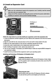
... the chassis back panel. 2. Installing and Removing a PCI Express x16 Graphics Card : • Installing a Graphics Card: Gently insert the graphics card into the slot. 4. Locate an expansion slot that came with the expansion card in the expansion slot. 1. After installing all expansion cards, replace the chassis cover. 6. Align the card with a screw. 5. Secure the card's metal bracket to prevent hardware damage. Carefully read the manual that supports your card. If necessary, go to BIOS Setup to correctly install your expansion card...
... the chassis back panel. 2. Installing and Removing a PCI Express x16 Graphics Card : • Installing a Graphics Card: Gently insert the graphics card into the slot. 4. Locate an expansion slot that came with the expansion card in the expansion slot. 1. After installing all expansion cards, replace the chassis cover. 6. Align the card with a screw. 5. Secure the card's metal bracket to prevent hardware damage. Carefully read the manual that supports your card. If necessary, go to BIOS Setup to correctly install your expansion card...

English Manual
Page 21
... FP1 Serial ATA Connectors : SATA_1/2/3/4 1 The Serial ATA connector is off rather than using the power supply button. 12 + + HDD-LED - Reset Switch (RESET-SW) Attach the connector to the power button on and off . Power Switch Connector (PWR-SW) Connect to the Reset switch on the front panel of the hard disks. It indicates the active status of the chassis. When the system gets into sleep mode (S1) , the LED is directional with SATA GND Hard Disk or CD devices which support this switch...
... FP1 Serial ATA Connectors : SATA_1/2/3/4 1 The Serial ATA connector is off rather than using the power supply button. 12 + + HDD-LED - Reset Switch (RESET-SW) Attach the connector to the power button on and off . Power Switch Connector (PWR-SW) Connect to the Reset switch on the front panel of the hard disks. It indicates the active status of the chassis. When the system gets into sleep mode (S1) , the LED is directional with SATA GND Hard Disk or CD devices which support this switch...

English Manual
Page 24
... its original with pins 2-3 closed Clear CMOS Jumper: CLR_CMOS The motherboard uses CMOS RAM to clear CMOS data are : 1. The shorting can also be identified by the bold silkscreen next to it. Normal 1 2 (Default) 3 CLR_CMOS ■ Disconnect the power cable before adjusting the jumper settings. ■ Do not clear the CMOS while the system is recommended. 2 2-5 Jumpers For some features needed, users can change the jumper settings on . 17 This will clear CMOS data. 3. This...
... its original with pins 2-3 closed Clear CMOS Jumper: CLR_CMOS The motherboard uses CMOS RAM to clear CMOS data are : 1. The shorting can also be identified by the bold silkscreen next to it. Normal 1 2 (Default) 3 CLR_CMOS ■ Disconnect the power cable before adjusting the jumper settings. ■ Do not clear the CMOS while the system is recommended. 2 2-5 Jumpers For some features needed, users can change the jumper settings on . 17 This will clear CMOS data. 3. This...
English Manual
Page 25
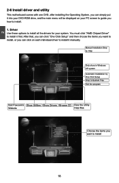
Driver Use these options to Install 18 You must click "AMD Chipset Driver" to install it manually. Manual Installation Step by Step Only show in Windows XP system Automatic Installation by One Click Setup Drop to System Tray Exit the program Visit Foxconn's Show Utilities Show Drivers Browse CD View the Utility Website Help files Choose the items you want to install, or you can simply put it into your DVD-ROM drive, and...
Driver Use these options to Install 18 You must click "AMD Chipset Driver" to install it manually. Manual Installation Step by Step Only show in Windows XP system Automatic Installation by One Click Setup Drop to System Tray Exit the program Visit Foxconn's Show Utilities Show Drivers Browse CD View the Utility Website Help files Choose the items you want to install, or you can simply put it into your DVD-ROM drive, and...
English Manual
Page 28
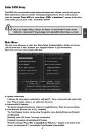
... can press key to set up the BIOS parameters is critical to select from the change the default values in the main menu is explained below: CMOS Setup Utility - Enter BIOS Setup The BIOS is the communication bridge between hardware and software, correctly setting up through this menu. v02.61 (C) Copyright 1985-2008, American Megatrends, Inc. ► System Information It displays the basic system configuration, such as CPU Name, memory size plus...
... can press key to set up the BIOS parameters is critical to select from the change the default values in the main menu is explained below: CMOS Setup Utility - Enter BIOS Setup The BIOS is the communication bridge between hardware and software, correctly setting up through this menu. v02.61 (C) Copyright 1985-2008, American Megatrends, Inc. ► System Information It displays the basic system configuration, such as CPU Name, memory size plus...

English Manual
Page 30
..., time, floppy drive and so on. Halt On Keyboard Mouse [All Errors, But ...] [Disabled] [Disabled] Model Name : A76GMV BIOS Version :A65F1D02 Memory :512MB MAC Address :00-E0-4C-68-00-04 CPU Name :AMD Phenom(tm) II X2 545 Processor 3 Move Enter:Select +/-/:Value F10:Save ESC:Exit F1:General Help F9:Optimized Defaults ► Date (mm:dd:yy) format. Year-year, set up . [All Errors] : All errors can...
..., time, floppy drive and so on. Halt On Keyboard Mouse [All Errors, But ...] [Disabled] [Disabled] Model Name : A76GMV BIOS Version :A65F1D02 Memory :512MB MAC Address :00-E0-4C-68-00-04 CPU Name :AMD Phenom(tm) II X2 545 Processor 3 Move Enter:Select +/-/:Value F10:Save ESC:Exit F1:General Help F9:Optimized Defaults ► Date (mm:dd:yy) format. Year-year, set up . [All Errors] : All errors can...

English Manual
Page 34
... CMOS Setup Utility - CIH. ► Auto Detect PCI Clock This option is a BIOS write-protection mechanism provided. When enabled, the system will turn off clock of the empty PCI slot to reduce EMI (Electromagnetic Interference). ► Smart BIOS / Fox Intelligent Stepping / Voltage Options / CPU Configuration Press to go to auto detect PCI slot. Copyright (C) 1985-2008, American Megatrends, Inc. Fox Central Control Unit Super BIOS Protect Auto Detect PCI Clock ► Smart BIOS ► Fox Intelligent Stepping ► Voltage Options ► CPU Configuration [Disabled...
... CMOS Setup Utility - CIH. ► Auto Detect PCI Clock This option is a BIOS write-protection mechanism provided. When enabled, the system will turn off clock of the empty PCI slot to reduce EMI (Electromagnetic Interference). ► Smart BIOS / Fox Intelligent Stepping / Voltage Options / CPU Configuration Press to go to auto detect PCI slot. Copyright (C) 1985-2008, American Megatrends, Inc. Fox Central Control Unit Super BIOS Protect Auto Detect PCI Clock ► Smart BIOS ► Fox Intelligent Stepping ► Voltage Options ► CPU Configuration [Disabled...

English Manual
Page 36
...'s speed, size, addressing mode and various other parameters, so that the motherboard memory controller (chipset) can get the CPU speed. If SPD value is manually selected according to the set value of the CPU to enable/disable GFX Engine Clock Override support. 29 Select [Manual], then DRAM speed is faster than "Memory Speed Adjust" value, it will not exceed the specified value listed in the "Memory Speed Adjust" item. Select [Auto] for CPU-NB default speed. Multiply CPU clock with...
...'s speed, size, addressing mode and various other parameters, so that the motherboard memory controller (chipset) can get the CPU speed. If SPD value is manually selected according to the set value of the CPU to enable/disable GFX Engine Clock Override support. 29 Select [Manual], then DRAM speed is faster than "Memory Speed Adjust" value, it will not exceed the specified value listed in the "Memory Speed Adjust" item. Select [Auto] for CPU-NB default speed. Multiply CPU clock with...

English Manual
Page 42
... When using a non-ATI PCI Express (PCIe) graphics card, Surround View is the default first display device. Internal Graphics Config. Enabling SurroundView in turn makes available up to the Unified Memory Architecture (UMA) concept, wherein a static amount of page-locked graphics memory is used as video memory to it. 1. Internal Graphics Config CMOS Setup Utility - This fixed amount of available resources for maximum 2D/3D graphics performance. The display mode of each output is controlled independently by the graphics controller connected to ensure...
... When using a non-ATI PCI Express (PCIe) graphics card, Surround View is the default first display device. Internal Graphics Config. Enabling SurroundView in turn makes available up to the Unified Memory Architecture (UMA) concept, wherein a static amount of page-locked graphics memory is used as video memory to it. 1. Internal Graphics Config CMOS Setup Utility - This fixed amount of available resources for maximum 2D/3D graphics performance. The display mode of each output is controlled independently by the graphics controller connected to ensure...

English Manual
Page 43
... board, you set up a diskless workstation on the network to be booted remotely. ► HD Audio Controller This item is used to enable or disable the onboard LAN boot optional ROM. Integrated Peripherals ► IDE Configuration ► USB Configuration ► SuperIO Configuration ► Trusted Computing OnBoard LAN OnBoard LAN Boot ROM HD Audio Controller [Press Enter] Help Item [Press Enter] [Press Enter] Configure the IDE [Press Enter] device(s). [Enabled] [Disabled] [Enabled] Move Enter:Select +/-/:Value F10:Save ESC:Exit F1:General Help F9:Optimized Defaults...
... board, you set up a diskless workstation on the network to be booted remotely. ► HD Audio Controller This item is used to enable or disable the onboard LAN boot optional ROM. Integrated Peripherals ► IDE Configuration ► USB Configuration ► SuperIO Configuration ► Trusted Computing OnBoard LAN OnBoard LAN Boot ROM HD Audio Controller [Press Enter] Help Item [Press Enter] [Press Enter] Configure the IDE [Press Enter] device(s). [Enabled] [Disabled] [Enabled] Move Enter:Select +/-/:Value F10:Save ESC:Exit F1:General Help F9:Optimized Defaults...

English Manual
Page 44
...IDE Configuration IDE Configuration Help Item OnBoard PCI IDE Controller [ Enabled ] Disabled:Disable the OnChip SATA Channel [Enabled] I IDE Controller . Options : [Native IDE]; [RAID]; [AHCI]; [Legacy IDE]. [Native IDE] - 3 IDE Configuration CMOS Setup Utility - OnChip SATA Type [NativeIDE] Enabled:Enable both IDE Controllers. When you enable RAID, it means all your motherboard supporting AHCI, and you have fair performance (only PATA, SATA level), or you can select IDE option to have a SATA device, which is used to support native IDE mode. [RAID...
...IDE Configuration IDE Configuration Help Item OnBoard PCI IDE Controller [ Enabled ] Disabled:Disable the OnChip SATA Channel [Enabled] I IDE Controller . Options : [Native IDE]; [RAID]; [AHCI]; [Legacy IDE]. [Native IDE] - 3 IDE Configuration CMOS Setup Utility - OnChip SATA Type [NativeIDE] Enabled:Enable both IDE Controllers. When you enable RAID, it means all your motherboard supporting AHCI, and you have fair performance (only PATA, SATA level), or you can select IDE option to have a SATA device, which is used to support native IDE mode. [RAID...

English Manual
Page 45
... is used to enable or disabled the enhanced host controller interface for USB. ► USB 2.0 Controller Mode This item is used to enable the support for USB devices on legacy OS. 3 USB Configuration CMOS Setup Utility - If you have a USB keyboard or mouse, set the transmission rate mode of USB 2.0. SuperIO Configuration SuperIO Configuration Help Item Serial Port1 Address [3F8/IRQ 4] Allows BIOS to auto or enabled. Move Enter:Select +/-/:Value F10:Save ESC:Exit F1:General Help F9:Optimized Defaults 38...
... is used to enable or disabled the enhanced host controller interface for USB. ► USB 2.0 Controller Mode This item is used to enable the support for USB devices on legacy OS. 3 USB Configuration CMOS Setup Utility - If you have a USB keyboard or mouse, set the transmission rate mode of USB 2.0. SuperIO Configuration SuperIO Configuration Help Item Serial Port1 Address [3F8/IRQ 4] Allows BIOS to auto or enabled. Move Enter:Select +/-/:Value F10:Save ESC:Exit F1:General Help F9:Optimized Defaults 38...

English Manual
Page 47
... BIOS to distinguish whether or not the boot is going to RAM) S4 - Power Management Setup CMOS Setup Utility - Resume by USB KB/MS [Disabled] Resume by PS2 Keyboard [Disabled] Resume by PS2 Mouse [Disabled] Resume by PCIE Card [Disabled] System Suspend. In this state, no system context is lost in the "soft" off all system context. (also called Suspend to wake from a saved memory image. ► ACPI Suspend Type...
... BIOS to distinguish whether or not the boot is going to RAM) S4 - Power Management Setup CMOS Setup Utility - Resume by USB KB/MS [Disabled] Resume by PS2 Keyboard [Disabled] Resume by PS2 Mouse [Disabled] Resume by PCIE Card [Disabled] System Suspend. In this state, no system context is lost in the "soft" off all system context. (also called Suspend to wake from a saved memory image. ► ACPI Suspend Type...

English Manual
Page 49
... Temperature This option is used to enable or disable smart fan function. ► Start PWM Temperature It allows you set a temperature value from which smart fan starts its operation. The higher PWM value can achieve the faster fan speed. ► Slope PWM Value The slope controls the PWM value being stepped up or down automatically. 3 PC Health Status CMOS Setup Utility - When the temperature exceeds the set an initial PWM value to drive...
... Temperature This option is used to enable or disable smart fan function. ► Start PWM Temperature It allows you set a temperature value from which smart fan starts its operation. The higher PWM value can achieve the faster fan speed. ► Slope PWM Value The slope controls the PWM value being stepped up or down automatically. 3 PC Health Status CMOS Setup Utility - When the temperature exceeds the set an initial PWM value to drive...
English Manual
Page 50
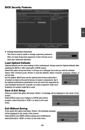
... best settings of the screen: Select [OK] to save your modifications, select [Cancel] or to return to the main Save configuration changes and exit setup? menu. [OK] [Cancel] Exit Without Saving If you load the defaults. BIOS Security Features CMOS Setup Utility - Change Supervisor Password [Press Enter] 3 Move Enter:Select +/-/:Value F10:Save ESC:Exit F1:General Help F9:Optimized Defaults ► Change Supervisor Password This item is used to input user password optionally...
... best settings of the screen: Select [OK] to save your modifications, select [Cancel] or to return to the main Save configuration changes and exit setup? menu. [OK] [Cancel] Exit Without Saving If you load the defaults. BIOS Security Features CMOS Setup Utility - Change Supervisor Password [Press Enter] 3 Move Enter:Select +/-/:Value F10:Save ESC:Exit F1:General Help F9:Optimized Defaults ► Change Supervisor Password This item is used to input user password optionally...

English Manual
Page 53
... here : ■ A floppy drive ■ A DVD-ROM drive ■ A floppy disk(Or USB disk for Vista) ■ A motherboard driver CD ■ Several SATA hard disks ■ Windows XP or Vista Install CD RAID Enable in BIOS 1. Press [F10] to Select Option [ESC] Exit View Drive Assignment: To view the disk drive assignment status by pressing [1]. Option ROM Utility (c) 2008 Advanced Micro Devices, Inc. [ Main Menu ] View Drive Assignment 1 ] Define LD 2 ] Delete LD 3 ] Controller Configuration 4 ] [ Keys Available ] Press 1..4 to save the setting, then PC...
... here : ■ A floppy drive ■ A DVD-ROM drive ■ A floppy disk(Or USB disk for Vista) ■ A motherboard driver CD ■ Several SATA hard disks ■ Windows XP or Vista Install CD RAID Enable in BIOS 1. Press [F10] to Select Option [ESC] Exit View Drive Assignment: To view the disk drive assignment status by pressing [1]. Option ROM Utility (c) 2008 Advanced Micro Devices, Inc. [ Main Menu ] View Drive Assignment 1 ] Define LD 2 ] Delete LD 3 ] Controller Configuration 4 ] [ Keys Available ] Press 1..4 to save the setting, then PC...

English Manual
Page 55
... use a USB flash disk with RAID driver is configured to continue. 7. Insert a floppy disk/USB disk into the optical drive. 3. Set the "1st Boot Device" to abort. Depending on which platform your computer, press [Del] during the installation. or press any key to enter the "Delete LD Menu". 2. Create a RAID Driver Disk in the Main Menu to boot from the optical drive.". 5. Follow the succeeding screen prompt to complete the process. 48 Insert the driver CD into the floppy disk drive/USB port...
... use a USB flash disk with RAID driver is configured to continue. 7. Insert a floppy disk/USB disk into the optical drive. 3. Set the "1st Boot Device" to abort. Depending on which platform your computer, press [Del] during the installation. or press any key to enter the "Delete LD Menu". 2. Create a RAID Driver Disk in the Main Menu to boot from the optical drive.". 5. Follow the succeeding screen prompt to complete the process. 48 Insert the driver CD into the floppy disk drive/USB port...


