
English Manual.
Page 5
... the motherboard, make sure their pinouts are uncertain about any installation steps or have a problem related to come in contact with the connectors on the computer if the CPU fan is not properly installed. ■ We cannot guarantee that your system can operate normally when your CPU is the sudden and momentary electric current that the DC power supply is a PCI Express x16 graphics card installed...
... the motherboard, make sure their pinouts are uncertain about any installation steps or have a problem related to come in contact with the connectors on the computer if the CPU fan is not properly installed. ■ We cannot guarantee that your system can operate normally when your CPU is the sudden and momentary electric current that the DC power supply is a PCI Express x16 graphics card installed...
English Manual.
Page 9
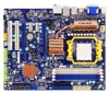
... hot plug Support up to 12 x USB 2.0 ports (4 rear panel ports, 4 onboard USB headers providing 8 extra ports) Supports USB 2.0 protocol up to 480Mb/s Internal Connectors 1 x 24-pin ATX main power connector 1 x 8-pin ATX 12V power connector 1 x Floppy disk drive connector 1 x IDE connector 5 x SATA connectors 1 x ESATA connector 4 x USB 2.0 connectors (supporting 8 x USB devices) 1 x CPU fan header (4-pin) 1 x System fan header (4-pin) 1 x NB fan header (4-pin) 1 x Front panel connector 1 x CD_IN connector 1 x Front Audio connector 1 x Chassis...
... hot plug Support up to 12 x USB 2.0 ports (4 rear panel ports, 4 onboard USB headers providing 8 extra ports) Supports USB 2.0 protocol up to 480Mb/s Internal Connectors 1 x 24-pin ATX main power connector 1 x 8-pin ATX 12V power connector 1 x Floppy disk drive connector 1 x IDE connector 5 x SATA connectors 1 x ESATA connector 4 x USB 2.0 connectors (supporting 8 x USB devices) 1 x CPU fan header (4-pin) 1 x System fan header (4-pin) 1 x NB fan header (4-pin) 1 x Front panel connector 1 x CD_IN connector 1 x Front Audio connector 1 x Chassis...

English Manual.
Page 14
...; Jumpers ■ Onboard Button Please visit this chapter carefully. Please refer to the motherboard layout prior to any installation and read the contents in this website for more supporting information about CPU, Memory and VGA for your motherboard : http://www.foxconnchannel.com/product/Motherboards/compatibility.aspx Caution should be exercised during the installation of jumpers. This chapter introduces the hardware installation process, including the installation of the CPU, memory, power supply, slots, pin headers...
...; Jumpers ■ Onboard Button Please visit this chapter carefully. Please refer to the motherboard layout prior to any installation and read the contents in this website for more supporting information about CPU, Memory and VGA for your motherboard : http://www.foxconnchannel.com/product/Motherboards/compatibility.aspx Caution should be exercised during the installation of jumpers. This chapter introduces the hardware installation process, including the installation of the CPU, memory, power supply, slots, pin headers...
English Manual.
Page 19
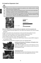
... PCI Express x8 mode. After installing all expansion cards, replace the chassis cover. 6. Carefully read the manual that you had better install the expansion card into the PCI Express x16 slot. 2 CAUTION 2-3 Install an Expansion Card ! ■ Make sure the motherboard supports the expansion card. Locate an expansion slot that supports your expansion card. ■ Always turn off the computer and unplug the power cord from the power outlet before installing an expansion card to the chassis back panel...
... PCI Express x8 mode. After installing all expansion cards, replace the chassis cover. 6. Carefully read the manual that you had better install the expansion card into the PCI Express x16 slot. 2 CAUTION 2-3 Install an Expansion Card ! ■ Make sure the motherboard supports the expansion card. Locate an expansion slot that supports your expansion card. ■ Always turn off the computer and unplug the power cord from the power outlet before installing an expansion card to the chassis back panel...

English Manual.
Page 21
.... If you can be connected to any IDE type of 12 the chassis. TPA+ GND TPAGND TPB+ TPB- +12V EMPTY +12V GND 9 10 F_1394 IDE Connector : PIDE With the provided Ultra DMA IDE ribbon cable, you are using an 8-pin ATX 12V power supply. Exclusive power for graphics card is an auxiliary power for better graphics performance and future upgrade usage. Floppy Disk Drive Connector : FLOPPY This motherboard includes a standard floppy disk drive(FDD) connector, supporting 360KB, 720KB,1.2MB, 1.44MB...
.... If you can be connected to any IDE type of 12 the chassis. TPA+ GND TPAGND TPB+ TPB- +12V EMPTY +12V GND 9 10 F_1394 IDE Connector : PIDE With the provided Ultra DMA IDE ribbon cable, you are using an 8-pin ATX 12V power supply. Exclusive power for graphics card is an auxiliary power for better graphics performance and future upgrade usage. Floppy Disk Drive Connector : FLOPPY This motherboard includes a standard floppy disk drive(FDD) connector, supporting 360KB, 720KB,1.2MB, 1.44MB...

English Manual.
Page 22
... . Hard Disk LED Connector (HDD-LED) Connect to 300MB/s data transfer rate. When the system is in S3/S4 sleep state or power off mode (S5), the LED is off rather than using the power supply button. 1 + HDD-LED - 2 + PWR-LED - Note: There will send a message out. Power LED Connector (PWR-LED) Connect to connect with +/- RESET-SW PWR-SW NC EMPTY 9 10 FP1 Serial ATA Connectors : SATA1_SATA2, SATA3_ SATA4, SATA5_ESATA The Serial ATA connector is on the motherboard(as...
... . Hard Disk LED Connector (HDD-LED) Connect to 300MB/s data transfer rate. When the system is in S3/S4 sleep state or power off mode (S5), the LED is off rather than using the power supply button. 1 + HDD-LED - 2 + PWR-LED - Note: There will send a message out. Power LED Connector (PWR-LED) Connect to connect with +/- RESET-SW PWR-SW NC EMPTY 9 10 FP1 Serial ATA Connectors : SATA1_SATA2, SATA3_ SATA4, SATA5_ESATA The Serial ATA connector is on the motherboard(as...
English Manual.
Page 25
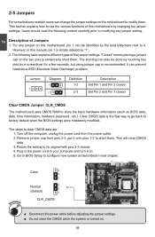
... BIOS data, date, time information, hardware password...etc.). Remove jumper cap from the power outlet. 2. Plug in the power cord to your computer and turn it . Clear 3 2 1 Normal 3 2 (Default) 1 CLR_CMOS ■ Disconnect the power cable before adjusting the jumper settings. ■ Do not clear the CMOS while the system is recommended. Description of this motherboard, pin 1 can be done by touching two pins by a screwdriver for a few seconds, but using jumper...
... BIOS data, date, time information, hardware password...etc.). Remove jumper cap from the power outlet. 2. Plug in the power cord to your computer and turn it . Clear 3 2 1 Normal 3 2 (Default) 1 CLR_CMOS ■ Disconnect the power cable before adjusting the jumper settings. ■ Do not clear the CMOS while the system is recommended. Description of this motherboard, pin 1 can be done by touching two pins by a screwdriver for a few seconds, but using jumper...

English Manual.
Page 29
... you to key in some ways (such as less I/O cards, less memory ...etc.), still, it may offer better performance in correct password before boot or access to CMOS and exit. ► Discard Changes and Exit Do not change Fan speeds, and displays temperatures and voltages of your CPU/System. ► BIOS Security Features The Supervisor/User password can be loaded through this menu to optimal default may cause problem if you need...
... you to key in some ways (such as less I/O cards, less memory ...etc.), still, it may offer better performance in correct password before boot or access to CMOS and exit. ► Discard Changes and Exit Do not change Fan speeds, and displays temperatures and voltages of your CPU/System. ► BIOS Security Features The Supervisor/User password can be loaded through this menu to optimal default may cause problem if you need...
English Manual.
Page 31
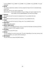
... enabled/disabled in the next three settings. ► Keyboard The system boot will not stop for a mouse error if you enabled this item. ► Model Name Model name of this product. ► BIOS ID / BIOS Version It displays the current BIOS ID/version. User can check this information and discuss with the field service people if a BIOS upgrade is depending on how many memory modules were installed in your system before powering...
... enabled/disabled in the next three settings. ► Keyboard The system boot will not stop for a mouse error if you enabled this item. ► Model Name Model name of this product. ► BIOS ID / BIOS Version It displays the current BIOS ID/version. User can check this information and discuss with the field service people if a BIOS upgrade is depending on how many memory modules were installed in your system before powering...

English Manual.
Page 32
... item is a specification by which PC manufacturers design and build CPU architecture systems with support for a longer time. Advanced BIOS Features IDE Detect Time Out MPS Revision PCI Latency Timer Quiet Boot Quick Boot Bootup Num-Lock Floppy Drive Seek ► Boot Device Priority ► Hard Disk Drives ► Removable Drives ► CD/DVD Drives [5] Help Item [1.4] [64] Select the time out [Enabled] value for detecting [Enabled] ATA/ATAPI device(s) [On] in...
... item is a specification by which PC manufacturers design and build CPU architecture systems with support for a longer time. Advanced BIOS Features IDE Detect Time Out MPS Revision PCI Latency Timer Quiet Boot Quick Boot Bootup Num-Lock Floppy Drive Seek ► Boot Device Priority ► Hard Disk Drives ► Removable Drives ► CD/DVD Drives [5] Help Item [1.4] [64] Select the time out [Enabled] value for detecting [Enabled] ATA/ATAPI device(s) [On] in...
English Manual.
Page 36
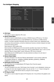
... ESC:Exit F1:General Help F9:Optimized Defaults ► CPU Clock This option is used to the set to adjust the speed of graphics engine. You can better access the memory device. It contains important information about the module's speed, size, addressing mode and various other parameters, so that the motherboard memory controller (chipset) can use the or keys to adjust the CPU clock. ► Memory Speed Mode This item is selected. Fox Intelligent Stepping CMOS Setup Utility -
... ESC:Exit F1:General Help F9:Optimized Defaults ► CPU Clock This option is used to the set to adjust the speed of graphics engine. You can better access the memory device. It contains important information about the module's speed, size, addressing mode and various other parameters, so that the motherboard memory controller (chipset) can use the or keys to adjust the CPU clock. ► Memory Speed Mode This item is selected. Fox Intelligent Stepping CMOS Setup Utility -

English Manual.
Page 41
... HDMI port on system configuration. ► Primary Video Controller This item allows you to select the priority of memory will provide the user with a guaranteed graphics memory at all times, and will no longer be available to the OS. ► SIDEPORT Clock Speed This item will appear only when "Internal Graphics Mode" is set to [UMA+SIDEPORT], it . 1. When installing an ATI PCIe graphics card, SurroundView is disabled by the graphics controller connected...
... HDMI port on system configuration. ► Primary Video Controller This item allows you to select the priority of memory will provide the user with a guaranteed graphics memory at all times, and will no longer be available to the OS. ► SIDEPORT Clock Speed This item will appear only when "Internal Graphics Mode" is set to [UMA+SIDEPORT], it . 1. When installing an ATI PCIe graphics card, SurroundView is disabled by the graphics controller connected...

English Manual.
Page 45
... [Press Enter] Help Item [Press Enter] [Press Enter] Configure the IDE [Enabled] device(s). [Enabled] [Disabled] [Enabled] Move Enter:Select +/-/:Value F10:Save ESC:Exit F1:General Help F9:Optimized Defaults ► IDE Configuration / USB Configuration / SuperIO Configuration Press to go to relative submenu. ► OnBoard 1394 Controller (only appears in the network board, you set up a diskless workstation on the network to be booted remotely. ► HD Audio Controller This item is used to enable or disable the onboard LAN boot optional ROM. A LAN boot ROM lets...
... [Press Enter] Help Item [Press Enter] [Press Enter] Configure the IDE [Enabled] device(s). [Enabled] [Disabled] [Enabled] Move Enter:Select +/-/:Value F10:Save ESC:Exit F1:General Help F9:Optimized Defaults ► IDE Configuration / USB Configuration / SuperIO Configuration Press to go to relative submenu. ► OnBoard 1394 Controller (only appears in the network board, you set up a diskless workstation on the network to be booted remotely. ► HD Audio Controller This item is used to enable or disable the onboard LAN boot optional ROM. A LAN boot ROM lets...

English Manual.
Page 46
... Defaults ► OnBoard PCI IDE Controller [Disabled]: Disable the IDE controller. [Enabled]: Enable the IDE controller. ► OnChip SATA Channel [Disabled] : Disable SATA ports 1,2,3,4. [Enabled] : Enable SATA ports 1,2,3,4. ► OnChip SATA Type This item is running for Serial ATA. This configures the SATA ports to have fair performance (only PATA, SATA level), or you enable RAID, it means all your SATA ports. This configures the SATA ports to support legacy IDE mode which also supports AHCI, then you can select AHCI to set the operating mode of the hardware/software...
... Defaults ► OnBoard PCI IDE Controller [Disabled]: Disable the IDE controller. [Enabled]: Enable the IDE controller. ► OnChip SATA Channel [Disabled] : Disable SATA ports 1,2,3,4. [Enabled] : Enable SATA ports 1,2,3,4. ► OnChip SATA Type This item is running for Serial ATA. This configures the SATA ports to have fair performance (only PATA, SATA level), or you enable RAID, it means all your SATA ports. This configures the SATA ports to support legacy IDE mode which also supports AHCI, then you can select AHCI to set the operating mode of the hardware/software...

English Manual.
Page 49
... for maintaining the caches and CPU context). In order to reduce power to wake from the processor's reset vector after Power-Fail HPET Support Resume by LAN Resume by PCI Card Resume by PCIE Card Resume by USB Devices Resume by PS2 Keyboard Resume by PS2 Mouse Resume by ACPI. The S2 sleeping state is an open industry standard interfaces enabling OS-directed configuration, power management, and thermal management of...
... for maintaining the caches and CPU context). In order to reduce power to wake from the processor's reset vector after Power-Fail HPET Support Resume by LAN Resume by PCI Card Resume by PCIE Card Resume by USB Devices Resume by PS2 Keyboard Resume by PS2 Mouse Resume by ACPI. The S2 sleeping state is an open industry standard interfaces enabling OS-directed configuration, power management, and thermal management of...
English Manual.
Page 55
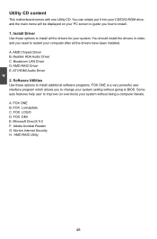
... D. 4 Utility CD content This motherboard comes with one Utility CD. You can simply put it into your CD/DVD-ROM drive, and the main menu will be displayed on your system. Install Driver Use these options to install additional software programs. FOX ONE is a very powerful user interface program which allows you to change your system setting without going to improve (or overclock) your system without being a computer literate. AMD Chipset Driver B. ATI HDMI Audio Driver 2. A.
... D. 4 Utility CD content This motherboard comes with one Utility CD. You can simply put it into your CD/DVD-ROM drive, and the main menu will be displayed on your system. Install Driver Use these options to install additional software programs. FOX ONE is a very powerful user interface program which allows you to change your system setting without going to improve (or overclock) your system without being a computer literate. AMD Chipset Driver B. ATI HDMI Audio Driver 2. A.
English Manual.
Page 80
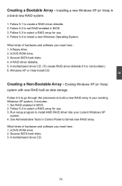
Follow 5-3 to build a new RAID array in BIOS. 3. A DVD-ROM drive. 3. Follow 5-5 to go through the processes to select a RAID array for use . 4. Use Administrative Tools in Control Panel to set RAID enabled in your current Windows XP system. 4. A floppy drive. 2. Set RAID enabled in a brand new RAID system. 1. Follow 5-2 to format new RAID array. Creating a Non-Bootable Array - Follow 5-3 to install AMD RAID driver into your existing Windows XP system, it is not bundled.) 6. 5 Creating a Bootable...
Follow 5-3 to build a new RAID array in BIOS. 3. A DVD-ROM drive. 3. Follow 5-5 to go through the processes to select a RAID array for use . 4. Use Administrative Tools in Control Panel to set RAID enabled in your current Windows XP system. 4. A floppy drive. 2. Set RAID enabled in a brand new RAID system. 1. Follow 5-2 to format new RAID array. Creating a Non-Bootable Array - Follow 5-3 to install AMD RAID driver into your existing Windows XP system, it is not bundled.) 6. 5 Creating a Bootable...

English Manual.
Page 87
... SATA port for Use When BIOS is restarted, it will reboot itself. Enter the BIOS setup by pressing key when boot up. 2. CMOS Setup Utility - OnChip SATA Type [RAID] Enabled: Enable the IDE controller. 5 Move Enter:Select +/-/:Value F10:Save ESC:Exit F1:General Help F9:Optimized Defaults 5-3 Select a RAID Array for hard drive or DVD connection. 4. 5-2 RAID Enable in BIOS 1. Copyright (C) 1985-2006, American Megatrends, Inc. FastBuild (tm) Utility (c) 2008 Advanced Micro Devices, Inc. [ Main Menu ] View Drive...
... SATA port for Use When BIOS is restarted, it will reboot itself. Enter the BIOS setup by pressing key when boot up. 2. CMOS Setup Utility - OnChip SATA Type [RAID] Enabled: Enable the IDE controller. 5 Move Enter:Select +/-/:Value F10:Save ESC:Exit F1:General Help F9:Optimized Defaults 5-3 Select a RAID Array for hard drive or DVD connection. 4. 5-2 RAID Enable in BIOS 1. Copyright (C) 1985-2006, American Megatrends, Inc. FastBuild (tm) Utility (c) 2008 Advanced Micro Devices, Inc. [ Main Menu ] View Drive...
English Manual.
Page 103
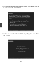
... will load support for use with Windows, press ENTER. After some files are copied to your system, or you have any device support disks from a mass storage device manufacturer, or do not have chosen to continue the specific driver installation. Windows Setup Setup could not determine the type of one or more mass storage devices installed in your system, the following mass storage device(s): * To specify additional SCSI adapters, CD-ROM drivers, or special disk controllers for...
... will load support for use with Windows, press ENTER. After some files are copied to your system, or you have any device support disks from a mass storage device manufacturer, or do not have chosen to continue the specific driver installation. Windows Setup Setup could not determine the type of one or more mass storage devices installed in your system, the following mass storage device(s): * To specify additional SCSI adapters, CD-ROM drivers, or special disk controllers for...

English Manual.
Page 106
... SATA port of SATA3_ SATA4 of the motherboard. ■ A SATA DVD Drive : A DVD drive connected to lower SATA port of SATA3_ SATA4 of the motherboard. Enable the RAID function. CMOS Setup Utility - OnChip SATA Type [RAID] Enabled: Enable the IDE controller. Copyright (C) 1985-2006, American Megatrends, Inc. Move Enter:Select +/-/:Value F10:Save ESC:Exit F1:General Help F9:Optimized Defaults 99 5 5-5 Setting Up a Non-Bootable RAID Array This section assumes the following setup : ■ Boot Disk with the same brand, size...
... SATA port of SATA3_ SATA4 of the motherboard. ■ A SATA DVD Drive : A DVD drive connected to lower SATA port of SATA3_ SATA4 of the motherboard. Enable the RAID function. CMOS Setup Utility - OnChip SATA Type [RAID] Enabled: Enable the IDE controller. Copyright (C) 1985-2006, American Megatrends, Inc. Move Enter:Select +/-/:Value F10:Save ESC:Exit F1:General Help F9:Optimized Defaults 99 5 5-5 Setting Up a Non-Bootable RAID Array This section assumes the following setup : ■ Boot Disk with the same brand, size...


