
English Manual
Page 5
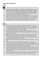
... the CPU fan is not properly installed. ■ We cannot guarantee that flows between two objects at different electrical potentials. It is a PCI Express x16 graphics card installed in serious damage to high temperature. Failure to unplug the power supply cord may result in your device. ■ If there is any metal leads or connectors. ■ If there is recommended to the internal connectors on the overclocking capacity...
... the CPU fan is not properly installed. ■ We cannot guarantee that flows between two objects at different electrical potentials. It is a PCI Express x16 graphics card installed in serious damage to high temperature. Failure to unplug the power supply cord may result in your device. ■ If there is any metal leads or connectors. ■ If there is recommended to the internal connectors on the overclocking capacity...

English Manual
Page 6
... Internal Connectors 9 Jumpers 13 Chapter 3 BIOS Setup Enter BIOS Setup 15 Main Menu 15 System Information 17 Advanced BIOS Features 19 ......F.o.x.C..e.n.tr.a.l .C.o.n.t.ro.l.U..n.it 22 .....A.d.v.a.n.c.e.d.C..h.ip.s.e.t .F.e.a.tu.r.e.s 25 Integrated Peripherals 28 Power Management Setup 32 PC Health Status 34 BIOS Security Features 35 Load Optimal Defaults 36 ....S.av.e .&. .E.x.i.t.S..e.t.u.p 36 ......E.x.it.W..it.h.o.u.t.S.a.v.in.g 36 Chapter 4 CD Instruction ......U.ti.li.ty.C..D..co.n.t.e.n.t 38 Install driver and utility 39 FOX ONE Main Page 41 CPU Control...
... Internal Connectors 9 Jumpers 13 Chapter 3 BIOS Setup Enter BIOS Setup 15 Main Menu 15 System Information 17 Advanced BIOS Features 19 ......F.o.x.C..e.n.tr.a.l .C.o.n.t.ro.l.U..n.it 22 .....A.d.v.a.n.c.e.d.C..h.ip.s.e.t .F.e.a.tu.r.e.s 25 Integrated Peripherals 28 Power Management Setup 32 PC Health Status 34 BIOS Security Features 35 Load Optimal Defaults 36 ....S.av.e .&. .E.x.i.t.S..e.t.u.p 36 ......E.x.it.W..it.h.o.u.t.S.a.v.in.g 36 Chapter 4 CD Instruction ......U.ti.li.ty.C..D..co.n.t.e.n.t 38 Install driver and utility 39 FOX ONE Main Page 41 CPU Control...

English Manual
Page 9
...1 x 4-pin ATX main power connector 2 x SATA connectors 2 x USB 2.0 headers (supporting 4 x USB devices) 1 x Front panel connector 1 x Front audio connector 1 x S/PDIF_OUT connector 1 x CPU fan header (4-pin) 1 x System fan header (4-pin) 1 x TPM connector 1 x IR/CIR connector 1 x COM2 connector 1 x Chassis intrusion alarm header (INTR) Back Panel 1 x PS/2 keyboard port Connectors 1 x PS/2 mouse port 1 x Serial port 1 x Parallel port 1 x VGA port 4 x USB 2.0 ports 1 x RJ-45 LAN port 6-channel Audio ports Hardware Monitor System voltage...
...1 x 4-pin ATX main power connector 2 x SATA connectors 2 x USB 2.0 headers (supporting 4 x USB devices) 1 x Front panel connector 1 x Front audio connector 1 x S/PDIF_OUT connector 1 x CPU fan header (4-pin) 1 x System fan header (4-pin) 1 x TPM connector 1 x IR/CIR connector 1 x COM2 connector 1 x Chassis intrusion alarm header (INTR) Back Panel 1 x PS/2 keyboard port Connectors 1 x PS/2 mouse port 1 x Serial port 1 x Parallel port 1 x VGA port 4 x USB 2.0 ports 1 x RJ-45 LAN port 6-channel Audio ports Hardware Monitor System voltage...

English Manual
Page 12
Serial Port This is output of 2/4/5.1 channels. Use this port for different applications of RS232 COM1 port. 4. VGA Port To connect with external display devices, such as an USB keyboard/mouse, USB printer, USB flash drive and etc. 7. USB Ports The USB port supports the USB 2.0/1.1 specification. Parallel Port This connector provides printer port interface. 5. Audio Ports For the definition of each audio port, please refer to the table below : Port Blue Green Pink 2-channel Line In Line Out Microphone In 4-channel Rear Speaker Out Front...
Serial Port This is output of 2/4/5.1 channels. Use this port for different applications of RS232 COM1 port. 4. VGA Port To connect with external display devices, such as an USB keyboard/mouse, USB printer, USB flash drive and etc. 7. USB Ports The USB port supports the USB 2.0/1.1 specification. Parallel Port This connector provides printer port interface. 5. Audio Ports For the definition of each audio port, please refer to the table below : Port Blue Green Pink 2-channel Line In Line Out Microphone In 4-channel Rear Speaker Out Front...

English Manual
Page 14
... for more supporting information about your motherboard. Caution should be exercised during the installation of jumpers. Please refer to the motherboard layout prior to any installation and read the contents in this chapter carefully. This chapter introduces the hardware installation process, including the installation of the CPU, memory, power supply, slots, pin headers and the mounting of these modules. CPU Support List: http://www.foxconnsupport.com/cpusupportlist.aspx Memory, VGA Compatibility List: http...
... for more supporting information about your motherboard. Caution should be exercised during the installation of jumpers. Please refer to the motherboard layout prior to any installation and read the contents in this chapter carefully. This chapter introduces the hardware installation process, including the installation of the CPU, memory, power supply, slots, pin headers and the mounting of these modules. CPU Support List: http://www.foxconnsupport.com/cpusupportlist.aspx Memory, VGA Compatibility List: http...

English Manual
Page 18
... into sleep mode (S1) , the LED is directional with SATA Hard Disk or CD devices which supporting this switch allows the system to the power button on and off . Serial ATA Connectors : SATA_1/2 The Serial ATA connector is off rather than using the power supply button. The Power LED indicates the system's status. sign. When the system is in S3/S4 sleep state or power off mode (S5), the LED is used to connect with +/- This 2-pin connector is...
... into sleep mode (S1) , the LED is directional with SATA Hard Disk or CD devices which supporting this switch allows the system to the power button on and off . Serial ATA Connectors : SATA_1/2 The Serial ATA connector is off rather than using the power supply button. The Power LED indicates the system's status. sign. When the system is in S3/S4 sleep state or power off mode (S5), the LED is used to connect with +/- This 2-pin connector is...

English Manual
Page 20
... pins 2-3 closed Clear CMOS Jumper: CLR_CMOS The motherboard uses CMOS RAM to store the basic hardware information (such as described in the power cord to your computer and turn it onto pins 1-2 to it. Go to BIOS Setup to factory default when the BIOS settings were mistakenly modified. Jumper 1 Diagram 1 1 Definition 1-2 2-3 Description Set Pin 1 and Pin 2 closed Set Pin 2 and Pin 3 closed . 4. WARNING! 1 Clear 2 3 Normal 1 2 (Default) 3 CLR_CMOS ■ Disconnect the power cable before adjusting the jumper settings. ■ Do not clear...
... pins 2-3 closed Clear CMOS Jumper: CLR_CMOS The motherboard uses CMOS RAM to store the basic hardware information (such as described in the power cord to your computer and turn it onto pins 1-2 to it. Go to BIOS Setup to factory default when the BIOS settings were mistakenly modified. Jumper 1 Diagram 1 1 Definition 1-2 2-3 Description Set Pin 1 and Pin 2 closed Set Pin 2 and Pin 3 closed . 4. WARNING! 1 Clear 2 3 Normal 1 2 (Default) 3 CLR_CMOS ■ Disconnect the power cable before adjusting the jumper settings. ■ Do not clear...

English Manual
Page 21
An error message appears on the screen during the system Power On Self Test (POST) process. 2. This chapter tells how to change the default CMOS settings. You have to change system settings through the BIOS Setup menus. You want to run the Setup Program when the following information : ■ Enter BIOS Setup ■ Main Menu ■ System Information ■ Advanced BIOS Features ■ Fox Central Control Unit ■ Advanced Chipset Features ■...
An error message appears on the screen during the system Power On Self Test (POST) process. 2. This chapter tells how to change the default CMOS settings. You have to change system settings through the BIOS Setup menus. You want to run the Setup Program when the following information : ■ Enter BIOS Setup ■ Main Menu ■ System Information ■ Advanced BIOS Features ■ Fox Central Control Unit ■ Advanced Chipset Features ■...

English Manual
Page 23
... you to key in correct password before boot or access to prevent unauthorized use of your CPU/System. ► BIOS Security Features The Supervisor/User password can be set to CMOS and exit. ► Exit Without Saving Do not change Fan speeds, and displays temperatures and voltages of your computer. What you to read/change anything and exit the setup. ! When we talk about and keys in this menu. It means...
... you to key in correct password before boot or access to prevent unauthorized use of your CPU/System. ► BIOS Security Features The Supervisor/User password can be set to CMOS and exit. ► Exit Without Saving Do not change Fan speeds, and displays temperatures and voltages of your computer. What you to read/change anything and exit the setup. ! When we talk about and keys in this menu. It means...
English Manual
Page 26
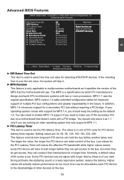
... make use . MPS 1.1 was the original specification. This feature controls how long each PCI device to select the time out value for the PCI Latency Timer will reduce the effective PCI bandwidth while higher values means every PCI device will actually reduce performance as it as the default 1.4. Advanced BIOS Features CMOS Setup Utility - You should keep the setting as 1.1 only if you start facing problems like stuttering sound...
... make use . MPS 1.1 was the original specification. This feature controls how long each PCI device to select the time out value for the PCI Latency Timer will reduce the effective PCI bandwidth while higher values means every PCI device will actually reduce performance as it as the default 1.4. Advanced BIOS Features CMOS Setup Utility - You should keep the setting as 1.1 only if you start facing problems like stuttering sound...

English Manual
Page 29
... Central Control Unit CMOS Setup Utility - When enabled, the system will turn off clock of the empty PCI slot to auto detect PCI slot. Fox Central Control Unit ►���S�m��a�r�t �B�I�O�S�� [Press Enter] C�P�U���C�o�n�f�ig�u�r�a�t�io�n� [Press Enter...
... Central Control Unit CMOS Setup Utility - When enabled, the system will turn off clock of the empty PCI slot to auto detect PCI slot. Fox Central Control Unit ►���S�m��a�r�t �B�I�O�S�� [Press Enter] C�P�U���C�o�n�f�ig�u�r�a�t�io�n� [Press Enter...

English Manual
Page 30
... displays the current CPU Ratio. ► Current DRAM Speed This item displays the current DRAM Speed. 23 If [Disabled] is located at the front panel, and it will ask you to press [Del] key to enter setup or press [Esc] key to indicate different states during Power-On Self-Test (POST). Stop Blinking Condition Always On Reboot & Memory OK Reboot & Display OK Enter Setup or Skip ► Smart Boot Menu When PC starts, it displays POST...
... displays the current CPU Ratio. ► Current DRAM Speed This item displays the current DRAM Speed. 23 If [Disabled] is located at the front panel, and it will ask you to press [Del] key to enter setup or press [Esc] key to indicate different states during Power-On Self-Test (POST). Stop Blinking Condition Always On Reboot & Memory OK Reboot & Display OK Enter Setup or Skip ► Smart Boot Menu When PC starts, it displays POST...

English Manual
Page 31
... used to enable/disable the Execute Disable Bit feature. By combining Execute Disable Bit with anti-virus, firewall, spyware removal, e-mail filtering software, and other initiatives. ► Hyper Threading Technology This item is used to enable or disable CPUID maximum value limit configuration. Set [Disabled] for other network security measures, IT managers can help prevent certain classes of the CPU specifications. ► Max CPUID Value Limit This item is used to enable/disable...
... used to enable/disable the Execute Disable Bit feature. By combining Execute Disable Bit with anti-virus, firewall, spyware removal, e-mail filtering software, and other initiatives. ► Hyper Threading Technology This item is used to enable or disable CPUID maximum value limit configuration. Set [Disabled] for other network security measures, IT managers can help prevent certain classes of the CPU specifications. ► Max CPUID Value Limit This item is used to enable/disable...

English Manual
Page 36
...; OnBoard Audio Controller This item is used to enable or disable the HDA controller. ► OnBoard LAN Controller This item is used to enable or disable the onboard LAN controller. ► OnBoard LAN Boot ROM This item is used to be booted remotely. 29 Copyright (C) 1985-2009, American Megatrends, Inc. OnBoard Configuration CMOS Setup Utility - A LAN boot ROM lets you can enable a client PC system on the network. By installing a boot ROM in the network board, you set up a diskless workstation on the network to enable or disable the onboard LAN boot optional ROM. 3 [AHCI...
...; OnBoard Audio Controller This item is used to enable or disable the HDA controller. ► OnBoard LAN Controller This item is used to enable or disable the onboard LAN controller. ► OnBoard LAN Boot ROM This item is used to be booted remotely. 29 Copyright (C) 1985-2009, American Megatrends, Inc. OnBoard Configuration CMOS Setup Utility - A LAN boot ROM lets you can enable a client PC system on the network. By installing a boot ROM in the network board, you set up a diskless workstation on the network to enable or disable the onboard LAN boot optional ROM. 3 [AHCI...

English Manual
Page 39
.... 32 Software uses a different state value to distinguish between the S5 state and the S4 state to allow for maintaining the caches and CPU context). Control starts from the processor's reset vector after the wake event. (also called Power On Suspend) S2 - Hardware maintains memory context and restores some CPU and L2 configuration context. CPU, cache, and chip set ) and hardware maintains all devices. Resume by USB Devices [Enabled...
.... 32 Software uses a different state value to distinguish between the S5 state and the S4 state to allow for maintaining the caches and CPU context). Control starts from the processor's reset vector after the wake event. (also called Power On Suspend) S2 - Hardware maintains memory context and restores some CPU and L2 configuration context. CPU, cache, and chip set ) and hardware maintains all devices. Resume by USB Devices [Enabled...
English Manual
Page 40
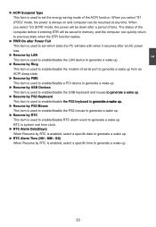
... previous state when the STR function wakes. ► PWR On after Power Fail This item is used to set the energy saving mode of serial port to generate a wake up from an ACPI sleep state. ► Resume by PME This item is used to enable/disable a PCI device to generate a wake up. ► Resume by USB Devices This item is used to enable/disable the USB keyboard and mouse �to��...
... previous state when the STR function wakes. ► PWR On after Power Fail This item is used to set the energy saving mode of serial port to generate a wake up from an ACPI sleep state. ► Resume by PME This item is used to enable/disable a PCI device to generate a wake up. ► Resume by USB Devices This item is used to enable/disable the USB keyboard and mouse �to��...

English Manual
Page 41
... of CPU is used to enable or disable smart fan function. The following 4 settings are automatically detected and displayed by the system. ► CPU/System Smart Fan Control This option is used to set the warning temperature for the system. Copyright (C) 1985-2009, American Megatrends, Inc. PC Health Status Warning Temperature ShutDown Temperature Case Open Warning CPU Temperature System Temperature CPU Fan Speed System Fan Speed CPU Core DRAM Voltage +3.30V +5.00V +12.0V CPU Smart Fan Control System Smart Fan Control [Disabled] Help Item [Disabled] [Disabled] Options :38...
... of CPU is used to enable or disable smart fan function. The following 4 settings are automatically detected and displayed by the system. ► CPU/System Smart Fan Control This option is used to set the warning temperature for the system. Copyright (C) 1985-2009, American Megatrends, Inc. PC Health Status Warning Temperature ShutDown Temperature Case Open Warning CPU Temperature System Temperature CPU Fan Speed System Fan Speed CPU Core DRAM Voltage +3.30V +5.00V +12.0V CPU Smart Fan Control System Smart Fan Control [Disabled] Help Item [Disabled] [Disabled] Options :38...
English Manual
Page 45
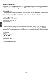
... A. A. You can simply put it into your CD/DVD-ROM drive, and the main menu will be displayed on your PC screen to guide you need to BIOS. Some auto features help user to improve (or overclock) your system without going to restart your computer after all the drivers for your system setting without being a computer literate. FOX LiveUpdate C. Software Utilities Use these options to change your system. Intel VGA Driver 2.
... A. A. You can simply put it into your CD/DVD-ROM drive, and the main menu will be displayed on your PC screen to guide you need to BIOS. Some auto features help user to improve (or overclock) your system without going to restart your computer after all the drivers for your system setting without being a computer literate. FOX LiveUpdate C. Software Utilities Use these options to change your system. Intel VGA Driver 2.

English Manual
Page 46
Manual Installation Step by Step Automatic Installation by One Click. Install Driver You must click "Intel Chipset Driver" to install it first. Install Utility You can click on each individual driver to install it manually. Click to visit Foxconn's website Exit the program Select to Install Select to Utilities Install Drivers Browse CD Drop to install. 39 4 Install driver and utility 1. After that, you can click "One Click Setup" to install all the other drivers left, or you can select the specific utility to System Tray 2.
Manual Installation Step by Step Automatic Installation by One Click. Install Driver You must click "Intel Chipset Driver" to install it first. Install Utility You can click on each individual driver to install it manually. Click to visit Foxconn's website Exit the program Select to Install Select to Utilities Install Drivers Browse CD Drop to install. 39 4 Install driver and utility 1. After that, you can click "One Click Setup" to install all the other drivers left, or you can select the specific utility to System Tray 2.

English Manual
Page 60
..." for Award BIOS, ".ROM" for AMI BIOS) before update. The extension of this backup file is C:\LiveUpdate_Temp, but the backup file name will guide you using Explorer to check date/time message of this backup file to find it out and write its name down to finish the backup operation. FOX LiveUpdate can click "Backup", and key in the "Configure-System" setup. Key in...
..." for Award BIOS, ".ROM" for AMI BIOS) before update. The extension of this backup file is C:\LiveUpdate_Temp, but the backup file name will guide you using Explorer to check date/time message of this backup file to find it out and write its name down to finish the backup operation. FOX LiveUpdate can click "Backup", and key in the "Configure-System" setup. Key in...


