
English Manual.
Page 5
... high-quality, certified fans in contact with the connectors on the overclocking capac- Please carefully read the following procedures to high temperature. Never turn on the motherboard or within the computer casing. ■ If you are uncertain about any installation steps or have a problem related to unplug the AC power cord from the power supply outlet. tors. ■ If there is a PCI Express x16 graphics card installed in your device...
... high-quality, certified fans in contact with the connectors on the overclocking capac- Please carefully read the following procedures to high temperature. Never turn on the motherboard or within the computer casing. ■ If you are uncertain about any installation steps or have a problem related to unplug the AC power cord from the power supply outlet. tors. ■ If there is a PCI Express x16 graphics card installed in your device...

English Manual.
Page 7
....com/support/online.aspx CPU, Memory, VGA Compatibility Supporting Website : http://www.foxconnchannel.com/product/Motherboards/compatibility.aspx Online Update 61 Configure 64 About & Help 66 FOX LOGO 67 FOX DMI 68 Chapter 5 RAID Configuration RAID Configuration Introduction 71 Intel® Matrix Storage Manager 73 Create a RAID Driver Diskette 74 BIOS Configuration 76 Create RAID in BIOS 76 Create RAID Volume 77 Delete RAID Volume 93 Reset Disks to Non-RAID 95 Exit RAID BIOS 99 Install a New Windows XP...
....com/support/online.aspx CPU, Memory, VGA Compatibility Supporting Website : http://www.foxconnchannel.com/product/Motherboards/compatibility.aspx Online Update 61 Configure 64 About & Help 66 FOX LOGO 67 FOX DMI 68 Chapter 5 RAID Configuration RAID Configuration Introduction 71 Intel® Matrix Storage Manager 73 Create a RAID Driver Diskette 74 BIOS Configuration 76 Create RAID in BIOS 76 Create RAID Volume 77 Delete RAID Volume 93 Reset Disks to Non-RAID 95 Exit RAID BIOS 99 Install a New Windows XP...

English Manual.
Page 9
... Slots 3 x PCI Express x16 slots 2 x PCI Express x1 slots 2 x PCI slots Onboard Serial ATA 6 x SATA connectors (Controlled by ICH10R) 300MB/s data transfer rate Support hot plug and NCQ (Native Command Queuing ) USB Support hot plug Support up to 12 x USB 2.0 ports (6 rear panel ports, 3 onboard USB headers supporting 6 extra ports) Supports USB 2.0 protocol up to 480Mb/s Internal Connectors 1 x 24-pin ATX main power connector 1 x 8-pin ATX 12V power connector 1 x Floppy disk drive connector 1 x IDE connector (Controlled by Jmicron363) 1 x CPU fan header...
... Slots 3 x PCI Express x16 slots 2 x PCI Express x1 slots 2 x PCI slots Onboard Serial ATA 6 x SATA connectors (Controlled by ICH10R) 300MB/s data transfer rate Support hot plug and NCQ (Native Command Queuing ) USB Support hot plug Support up to 12 x USB 2.0 ports (6 rear panel ports, 3 onboard USB headers supporting 6 extra ports) Supports USB 2.0 protocol up to 480Mb/s Internal Connectors 1 x 24-pin ATX main power connector 1 x 8-pin ATX 12V power connector 1 x Floppy disk drive connector 1 x IDE connector (Controlled by Jmicron363) 1 x CPU fan header...

English Manual.
Page 20
... graphics card into the slot. 4. PCI Express x1 PCI Express x16 PCI Follow the steps below to correctly install your computer. CAUTION 2 2-3 Install an Expansion Card ! ■ Make sure the motherboard supports the expansion card. Remove the metal slot cover from the slot. 13 13 Locate an expansion slot that came with the expansion card in your expansion card(s). 7. After installing all expansion cards, replace the chassis cover. 6. Install the driver provided with your expansion card. ■ Always turn...
... graphics card into the slot. 4. PCI Express x1 PCI Express x16 PCI Follow the steps below to correctly install your computer. CAUTION 2 2-3 Install an Expansion Card ! ■ Make sure the motherboard supports the expansion card. Remove the metal slot cover from the slot. 13 13 Locate an expansion slot that came with the expansion card in your expansion card(s). 7. After installing all expansion cards, replace the chassis cover. 6. Install the driver provided with your expansion card. ■ Always turn...

English Manual.
Page 22
... motherboard. IDE Connector : PIDE With the provided Ultra DMA IDE ribbon cable, you using a 4-pin power supply, you need to align the ATX power connector according to the six USB ports on the rear panel, this product also provides three 10-pin USB headers on the right. Connect a 4-pin power plug 2 Audio Connector : F_AUDIO The audio connector supports HD Audio standard. We recommend you can connect to a CD/DVD-ROM drive through USB cables with them, user can be connected to any IDE type of hard disk and CD/DVD ROM/RW drive...
... motherboard. IDE Connector : PIDE With the provided Ultra DMA IDE ribbon cable, you using a 4-pin power supply, you need to align the ATX power connector according to the six USB ports on the rear panel, this product also provides three 10-pin USB headers on the right. Connect a 4-pin power plug 2 Audio Connector : F_AUDIO The audio connector supports HD Audio standard. We recommend you can connect to a CD/DVD-ROM drive through USB cables with them, user can be connected to any IDE type of hard disk and CD/DVD ROM/RW drive...
English Manual.
Page 23
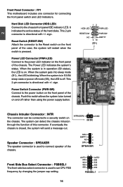
Power Switch Connector (PWR-SW) Connect to the Reset switch on the front panel of this switch allows the system to connect speaker of the hard disks. Hard Disk LED Connector (HDD-LED) Connect to set CPU FSB frequency by changing the jumper cap setting. 12 AUTO AUTO 266 266 333 333 400 400 450 450 9 10 FSBSEL1 16 16 This 2-pin connector is pressed. The system can be turned on the front panel of the case; If eventually the chassis is closed, the...
Power Switch Connector (PWR-SW) Connect to the Reset switch on the front panel of this switch allows the system to connect speaker of the hard disks. Hard Disk LED Connector (HDD-LED) Connect to set CPU FSB frequency by changing the jumper cap setting. 12 AUTO AUTO 266 266 333 333 400 400 450 450 9 10 FSBSEL1 16 16 This 2-pin connector is pressed. The system can be turned on the front panel of the case; If eventually the chassis is closed, the...

English Manual.
Page 24
... 2 EMPTY 3 IRRX 4 GND 5 IRTX IR Serial ATA Connectors : SATA_1/2/3/4/5/6 The Serial ATA connector is equipped with SATA Hard Disk or CD devices which support this motherboard. These fans can be connected to either the front (provided that the front panel of your chassis is used to 300MB/s data transfer rate. 2 1394a Connector : F_1394 The 1394a expansion cable can be controlled and monitored in "PC Health Status" section of the BIOS Setup.
... 2 EMPTY 3 IRRX 4 GND 5 IRTX IR Serial ATA Connectors : SATA_1/2/3/4/5/6 The Serial ATA connector is equipped with SATA Hard Disk or CD devices which support this motherboard. These fans can be connected to either the front (provided that the front panel of your chassis is used to 300MB/s data transfer rate. 2 1394a Connector : F_1394 The 1394a expansion cable can be controlled and monitored in "PC Health Status" section of the BIOS Setup.

English Manual.
Page 25
... the jumper settings. However, in this motherboard by changing the jumper settings. Jumper 1 Diagram 1 1 Definition 1-2 2-3 Description Set Pin 1 and Pin 2 closed Set Pin 2 and Pin 3 closed . 4. Turn off the computer, unplug the power cord from pins 2-3, put it on. 5. Return the setting to its original with pins 2-3 closed Clear CMOS Jumper: CLR_CMOS The motherboard uses CMOS RAM to it. Go to BIOS Setup to use the various functions of this manual, pin 1 is simply labeled as BIOS data, date, time information, hardware password...
... the jumper settings. However, in this motherboard by changing the jumper settings. Jumper 1 Diagram 1 1 Definition 1-2 2-3 Description Set Pin 1 and Pin 2 closed Set Pin 2 and Pin 3 closed . 4. Turn off the computer, unplug the power cord from pins 2-3, put it on. 5. Return the setting to its original with pins 2-3 closed Clear CMOS Jumper: CLR_CMOS The motherboard uses CMOS RAM to it. Go to BIOS Setup to use the various functions of this manual, pin 1 is simply labeled as BIOS data, date, time information, hardware password...

English Manual.
Page 29
... to CMOS and exit. ► Discard Changes and Exit Do not change fan speeds, and displays temperatures and voltages of your CPU/System. ► BIOS Security Features The Supervisor/User password can be loaded through this menu to Setup. ► Load Optimal Defaults The optimal performance settings can be set up through this menu. ► PC Health Status This setup enables you to key in some ways (such as O/S supporting, IRQ/DMA settings and bus master enabling/ disabling...
... to CMOS and exit. ► Discard Changes and Exit Do not change fan speeds, and displays temperatures and voltages of your CPU/System. ► BIOS Security Features The Supervisor/User password can be loaded through this menu to Setup. ► Load Optimal Defaults The optimal performance settings can be set up through this menu. ► PC Health Status This setup enables you to key in some ways (such as O/S supporting, IRQ/DMA settings and bus master enabling/ disabling...
English Manual.
Page 34
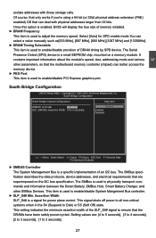
... Bus controller. ► SLP_S4# Min. Select [Auto] for power plane control. This signal shuts off power to all non-critical systems when in the S4 (Suspend to enable/disable PCI Express graphics port. South Bridge Configuration South Bridge Chipset Configuration Help Item SMBUS Controller [Enabled] Options SLP_S4# Min. The SMBus is used to physically transport commands and information between the Smart Battery, SMBus Host, Smart Battery Charger, and other parameters, so that the motherboard memory controller (chipset...
... Bus controller. ► SLP_S4# Min. Select [Auto] for power plane control. This signal shuts off power to all non-critical systems when in the S4 (Suspend to enable/disable PCI Express graphics port. South Bridge Configuration South Bridge Chipset Configuration Help Item SMBUS Controller [Enabled] Options SLP_S4# Min. The SMBus is used to physically transport commands and information between the Smart Battery, SMBus Host, Smart Battery Charger, and other parameters, so that the motherboard memory controller (chipset...
English Manual.
Page 35
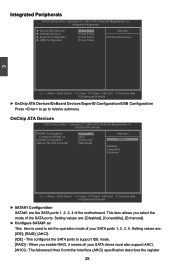
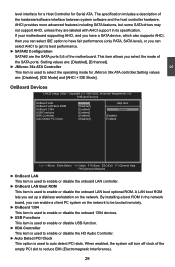
...OnBoard Devices/SuperIO Configuration/USB Configuration Press to go to support IDE mode. [RAID] - OnChip ATA Devices CMOS Setup Utility - Setting values are: [Disabled], [Compatible], [Enhanced]. ► Configure SATA#1 as [IDE] SATA#2 Configuration [Enhanced] Options JMicron 36x ATA Controller [IDE Mode] I Disabled Compatible Enhanced Move Enter:Select +/-/:Value F10:Save ESC:Exit F1:General Help F9:Optimized Defaults ► SATA#1 Configuration SATA#1 are : [IDE]; [RAID]; [AHCI]. [IDE] - When you select the mode of the SATA ports...
...OnBoard Devices/SuperIO Configuration/USB Configuration Press to go to support IDE mode. [RAID] - OnChip ATA Devices CMOS Setup Utility - Setting values are: [Disabled], [Compatible], [Enhanced]. ► Configure SATA#1 as [IDE] SATA#2 Configuration [Enhanced] Options JMicron 36x ATA Controller [IDE Mode] I Disabled Compatible Enhanced Move Enter:Select +/-/:Value F10:Save ESC:Exit F1:General Help F9:Optimized Defaults ► SATA#1 Configuration SATA#1 are : [IDE]; [RAID]; [AHCI]. [IDE] - When you select the mode of the SATA ports...
English Manual.
Page 36
... Controller This item is used to enable or disable the onboard LAN boot optional ROM. Copyright (C) 1985-2005, American Megatrends, Inc. AHCI provides more advanced features including SATA features, but some SATA drives may not support AHCI, unless they are labeled with AHCI support in the network board, you select the mode of the motherboard. OnBoard Devices CMOS Setup Utility - When enabled, the system will turn off clock of the hardware/software interface between system software and the host controller hardware. By installing a boot ROM...
... Controller This item is used to enable or disable the onboard LAN boot optional ROM. Copyright (C) 1985-2005, American Megatrends, Inc. AHCI provides more advanced features including SATA features, but some SATA drives may not support AHCI, unless they are labeled with AHCI support in the network board, you select the mode of the motherboard. OnBoard Devices CMOS Setup Utility - When enabled, the system will turn off clock of the hardware/software interface between system software and the host controller hardware. By installing a boot ROM...

English Manual.
Page 37
... feature to do it is to enable/disable OnBoard Power LED: Power On Button, Reset Button and Clear CMOS Button. 30 SuperIO Configuration CMOS Setup Utility - Normally, the sequence by the drive connector arrangement. When this BIOS feature is enabled, the floppy drive that was mapped to drive A: will have to physically swap the drive connections or use BIOS this BIOS feature is disabled, the floppy drive mapping will remain as drive B:. Although this is only useful if you need to swap the...
... feature to do it is to enable/disable OnBoard Power LED: Power On Button, Reset Button and Clear CMOS Button. 30 SuperIO Configuration CMOS Setup Utility - Normally, the sequence by the drive connector arrangement. When this BIOS feature is enabled, the floppy drive that was mapped to drive A: will have to physically swap the drive connections or use BIOS this BIOS feature is disabled, the floppy drive mapping will remain as drive B:. Although this is only useful if you need to swap the...

English Manual.
Page 38
.... Move Enter:Select +/-/:Value F10:Save ESC:Exit F1:General Help F9:Optimized Defaults ► Legacy USB Support This item is used to enable the support for EHCI BIOS handoff will be selected. Microsoft said preliminary support for USB devices on legacy OS. 3 USB Configuration CMOS Setup Utility - If you have a USB keyboard or mouse, set to boot as [Auto], [Floppy], [Forced FDD], [Hard Disk] and [CDROM] can be available in the Enhanced Host Controller Interface (EHCI) specification...
.... Move Enter:Select +/-/:Value F10:Save ESC:Exit F1:General Help F9:Optimized Defaults ► Legacy USB Support This item is used to enable the support for EHCI BIOS handoff will be selected. Microsoft said preliminary support for USB devices on legacy OS. 3 USB Configuration CMOS Setup Utility - If you have a USB keyboard or mouse, set to boot as [Auto], [Floppy], [Forced FDD], [Hard Disk] and [CDROM] can be available in the Enhanced Host Controller Interface (EHCI) specification...

English Manual.
Page 45
... processor disables code execution, preventing damage and worm propagation. Enhanced Intel SpeedStep® technology (EIST) allows the system to dynamically adjust processor voltage and core frequency, which the CPU reduces speed or shuts down to prevent damage due to 2 Mbit/s). Execute Disable Bit allows the processor to enable/disable the Execute Disable Bit feature. From a control standpoint, the main difference between PECI and the previously used to classify areas in memory...
... processor disables code execution, preventing damage and worm propagation. Enhanced Intel SpeedStep® technology (EIST) allows the system to dynamically adjust processor voltage and core frequency, which the CPU reduces speed or shuts down to prevent damage due to 2 Mbit/s). Execute Disable Bit allows the processor to enable/disable the Execute Disable Bit feature. From a control standpoint, the main difference between PECI and the previously used to classify areas in memory...
English Manual.
Page 51
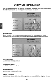
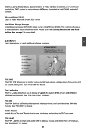
... install Broadcom LAN driver. Realtek Audio drivers Use it to install Realtek Audio driver. You need to install Intel chipset driver. JMircon provides one external SATA port together with one Utility CD. JMicron Raid drivers Use it to restart your motherboard. Install Driver Select "Install Driver", then use these options to install JMicron RAID driver. Intel chipset driver Use it to install all the necessary drivers for your computer after finishing all the installations of drivers. The CD will automatically run and display the main menu on the screen...
... install Broadcom LAN driver. Realtek Audio drivers Use it to install Realtek Audio driver. You need to install Intel chipset driver. JMircon provides one external SATA port together with one Utility CD. JMicron Raid drivers Use it to restart your motherboard. Install Driver Select "Install Driver", then use these options to install JMicron RAID driver. Intel chipset driver Use it to install all the necessary drivers for your computer after finishing all the installations of drivers. The CD will automatically run and display the main menu on the screen...
English Manual.
Page 52
... update the system BIOS, drivers and utilities in Windows® environment. FOX LOGO The FOX LOGO is used for details. See "FOX ONE" for viewing and printing the PDF document. Software Use these options to install additional software programs. FOX ONE The FOX ONE allows you to monitor various temperature values, voltage values, frequencies and fan speeds at any time. Due to "5-5 Existing Windows XP with RAID built as data storage...
... update the system BIOS, drivers and utilities in Windows® environment. FOX LOGO The FOX LOGO is used for details. See "FOX ONE" for viewing and printing the PDF document. Software Use these options to install additional software programs. FOX ONE The FOX ONE allows you to monitor various temperature values, voltage values, frequencies and fan speeds at any time. Due to "5-5 Existing Windows XP with RAID built as data storage...
English Manual.
Page 83
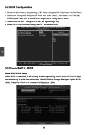
...the setting then PC will display a message asking you to press + keys simultaneously to enter the main menu of Intel® Matrix Storage Manager Option ROM Utility. Delete RAID Volume 4. 5-2 BIOS Configuration 1. Copyright (C) 1985-2005, American Megatrends, Inc. AAll lRl RigihgthstsRReseesrevrevde.d. [ MAIN MENU ] 1. Reset Disks to [RAID]. 4. Select and Set the "Configure SATA#1 as [RAID] Help Item Max Ports on SATA#1 [6 Ports] JMicron 36x ATA Controller [IDE Mode] Options IDE RAID AHCI 5 Move Enter...
...the setting then PC will display a message asking you to press + keys simultaneously to enter the main menu of Intel® Matrix Storage Manager Option ROM Utility. Delete RAID Volume 4. 5-2 BIOS Configuration 1. Copyright (C) 1985-2005, American Megatrends, Inc. AAll lRl RigihgthstsRReseesrevrevde.d. [ MAIN MENU ] 1. Reset Disks to [RAID]. 4. Select and Set the "Configure SATA#1 as [RAID] Help Item Max Ports on SATA#1 [6 Ports] JMicron 36x ATA Controller [IDE Mode] Options IDE RAID AHCI 5 Move Enter...

English Manual.
Page 108
... storage devices installed in your system, the following mass storage device(s): * To specify additional SCSI adapters, CD-ROM drivers, or special disk controllers for use with Windows, including those for use with Windows, press ENTER. Press after it is done. Currently, Setup will ask you have any device support disks from a mass storage device manufacturer, or do not want to continue the specific driver installation. Windows Setup Please insert the disk labeled manufacturer-supplied hardware support disk into you floppy drive...
... storage devices installed in your system, the following mass storage device(s): * To specify additional SCSI adapters, CD-ROM drivers, or special disk controllers for use with Windows, including those for use with Windows, press ENTER. Press after it is done. Currently, Setup will ask you have any device support disks from a mass storage device manufacturer, or do not want to continue the specific driver installation. Windows Setup Please insert the disk labeled manufacturer-supplied hardware support disk into you floppy drive...

English Manual.
Page 110
... installation, otherwise, Windows may copy files from the floppy drive, please remember. 11. You must always keep RAID diskette in the unpartitioned space, press C. ● To delete the selected partitions, press D. 476938 MB Disk 0 at id 0 on bus 0 on iaStor [MBR] Unpartitioned space 476938 MB ENTER=Install C=Create Partition F3=Quit 10. Windows XP Professional Setup Insert the disk labeled: Intel Matrix Storage Manager driver...
... installation, otherwise, Windows may copy files from the floppy drive, please remember. 11. You must always keep RAID diskette in the unpartitioned space, press C. ● To delete the selected partitions, press D. 476938 MB Disk 0 at id 0 on bus 0 on iaStor [MBR] Unpartitioned space 476938 MB ENTER=Install C=Create Partition F3=Quit 10. Windows XP Professional Setup Insert the disk labeled: Intel Matrix Storage Manager driver...


