
English Manual.
Page 1
ELA Series Motherboard User's Manual
ELA Series Motherboard User's Manual

English Manual.
Page 2
... you to avoid problems. WARNING! All trade names are for reference only, please refer to the physical motherboard for ELA Series motherboard. More information: If you how to use of Foxconn, Inc. P/N: 3A2210R00-000-G Symbol description: ! All images are registered trademarks of respective manufacturers listed. By... which could otherwise be caused by inappropriate waste handling of this product may not be changed or modified at any time, Foxconn does not obligate itself to inform the user of these changes. Trademark: All trademarks are the property of hardware damage or...
... you to avoid problems. WARNING! All trade names are for reference only, please refer to the physical motherboard for ELA Series motherboard. More information: If you how to use of Foxconn, Inc. P/N: 3A2210R00-000-G Symbol description: ! All images are registered trademarks of respective manufacturers listed. By... which could otherwise be caused by inappropriate waste handling of this product may not be changed or modified at any time, Foxconn does not obligate itself to inform the user of these changes. Trademark: All trademarks are the property of hardware damage or...
English Manual.
Page 3
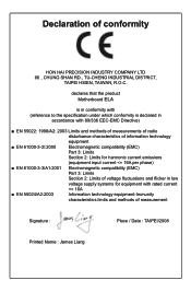
declares that the product Motherboard ELA is in conformity with (reference to the specification under which conformity is declared in accordance with 89/336 EEC-EMC Directive) ■ EN 55022: 1998/...
declares that the product Motherboard ELA is in conformity with (reference to the specification under which conformity is declared in accordance with 89/336 EEC-EMC Directive) ■ EN 55022: 1998/...
English Manual.
Page 4
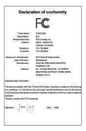
...Operation is subject to comply with Part 15 of conformity Trade Name: Model Name: Responsible Party: Address: Telephone: Facsimile: FOXCONN ELA PCE Industry Inc. 458 E. Supplementary Information: This device complies with FCC standards. Declaration of the FCC Rules. Tested to ...CA 92835 714-738-8868 714-738-8838 Equipment Classification: Type of Product: Manufacturer: Address: FCC Class B Subassembly Motherboard HON HAI PRECISION INDUSTRY COMPANY LTD 66 , CHUNG SHAN RD., TU-CHENG INDUSTRIAL DISTRICT, TAIPEI HSIEN, TAIWAN, R.O.C. Signature : Date : 2008
...Operation is subject to comply with Part 15 of conformity Trade Name: Model Name: Responsible Party: Address: Telephone: Facsimile: FOXCONN ELA PCE Industry Inc. 458 E. Supplementary Information: This device complies with FCC standards. Declaration of the FCC Rules. Tested to ...CA 92835 714-738-8868 714-738-8838 Equipment Classification: Type of Product: Manufacturer: Address: FCC Class B Subassembly Motherboard HON HAI PRECISION INDUSTRY COMPANY LTD 66 , CHUNG SHAN RD., TU-CHENG INDUSTRIAL DISTRICT, TAIPEI HSIEN, TAIWAN, R.O.C. Signature : Date : 2008

English Manual.
Page 5
... or connec- Also, make sure there are no leftover screws or metal components placed on the motherboard. Incorrect connections might damage the motherboard. ■ When handling the motherboard, avoid touching any installation steps or have a problem related to your electronic equipment. It is... discharge (ESD) wrist strap when handling components such as a spark which will quickly damage your system. Normally it comes out as a motherboard, CPU or memory. ■ Ensure that flows between two objects at different electrical potentials. tors. ■ If there is a PCI...
... or connec- Also, make sure there are no leftover screws or metal components placed on the motherboard. Incorrect connections might damage the motherboard. ■ When handling the motherboard, avoid touching any installation steps or have a problem related to your electronic equipment. It is... discharge (ESD) wrist strap when handling components such as a spark which will quickly damage your system. Normally it comes out as a motherboard, CPU or memory. ■ Ensure that flows between two objects at different electrical potentials. tors. ■ If there is a PCI...

English Manual.
Page 7
...://www.foxconnsupport.com Worldwide online contact Support : http://www.foxconnchannel.com/support/online.aspx CPU, Memory, VGA Compatibility Supporting Website : http://www.foxconnchannel.com/product/Motherboards/compatibility.aspx Online Update 61 Configure 64 About & Help 66 FOX LOGO 67 FOX DMI 68 Chapter 5 RAID Configuration RAID Configuration Introduction 71 Intel®...
...://www.foxconnsupport.com Worldwide online contact Support : http://www.foxconnchannel.com/support/online.aspx CPU, Memory, VGA Compatibility Supporting Website : http://www.foxconnchannel.com/product/Motherboards/compatibility.aspx Online Update 61 Configure 64 About & Help 66 FOX LOGO 67 FOX DMI 68 Chapter 5 RAID Configuration RAID Configuration Introduction 71 Intel®...

English Manual.
Page 8
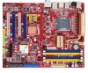
Foxconn products are engineered to unleash more power from your computer. This chapter includes the following information: ■ Product Specifications ■ Layout ■ Back Panel Connectors Thank you need for buying Foxconn ELA Series motherboard. With advanced overclocking capability and a range of connectivity features for today multi-media computing requirements, ELA enables you to maximize computing power, providing only what you for break-through performance.
Foxconn products are engineered to unleash more power from your computer. This chapter includes the following information: ■ Product Specifications ■ Layout ■ Back Panel Connectors Thank you need for buying Foxconn ELA Series motherboard. With advanced overclocking capability and a range of connectivity features for today multi-media computing requirements, ELA enables you to maximize computing power, providing only what you for break-through performance.

English Manual.
Page 11
... 14. Buzzer 20. Speaker Connector 22. Chassis Intrusion Alarm Header 24. DDR2 DIMM Slots 27. CPU_FAN Header 30. LGA 775 CPU Socket Note : The above motherboard layout is for reference only, please refer to the physical...
... 14. Buzzer 20. Speaker Connector 22. Chassis Intrusion Alarm Header 24. DDR2 DIMM Slots 27. CPU_FAN Header 30. LGA 775 CPU Socket Note : The above motherboard layout is for reference only, please refer to the physical...
English Manual.
Page 14
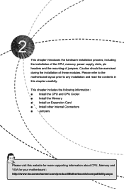
... prior to any installation and read the contents in this website for more supporting information about CPU, Memory and VGA for your motherboard : http://www.foxconnchannel.com/product/Motherboards/compatibility.aspx This chapter includes the following information : ■ Install the CPU and CPU Cooler ■ Install the Memory ■ Install an Expansion...
... prior to any installation and read the contents in this website for more supporting information about CPU, Memory and VGA for your motherboard : http://www.foxconnchannel.com/product/Motherboards/compatibility.aspx This chapter includes the following information : ■ Install the CPU and CPU Cooler ■ Install the Memory ■ Install an Expansion...

English Manual.
Page 15
... Socket Notch Pin-1 triangle marking of the CPU. Hyper-Threading Technology System Requirements: (Go to install the CPU : ■ Make sure that the motherboard supports the CPU. ■ Always turn on the computer if the CPU cooler is not installed, otherwise overheating and damage of the CPU may locate...; An operating system that is not recommended that supports HT Technology and has it enabled Install the CPU Locate the alignment keys on the motherboard CPU socket and the notches on the surface of the CPU. ■ Do not turn off the computer and unplug the power cord from...
... Socket Notch Pin-1 triangle marking of the CPU. Hyper-Threading Technology System Requirements: (Go to install the CPU : ■ Make sure that the motherboard supports the CPU. ■ Always turn on the computer if the CPU cooler is not installed, otherwise overheating and damage of the CPU may locate...; An operating system that is not recommended that supports HT Technology and has it enabled Install the CPU Locate the alignment keys on the motherboard CPU socket and the notches on the surface of the CPU. ■ Do not turn off the computer and unplug the power cord from...
English Manual.
Page 17
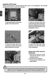
.... 3. That's it. 3. Check the solder side of CPU cooler from the top, and the bolts will be fixed as the example.) 1. Release bolts of the motherboard, the push pin should be fastened on the surface of arrow (counterclockwise). 2. Turning push pin clockwise to correctly install the CPU cooler on the... cooler because the thermal grease may damage the CPU. 10 10 Inadequately removing the CPU cooler may adhere to the CPU FAN header on the motherboard. (The following procedures use Foxconn cooler as depicted in the picture. 3 2 1 4.
.... 3. That's it. 3. Check the solder side of CPU cooler from the top, and the bolts will be fixed as the example.) 1. Release bolts of the motherboard, the push pin should be fastened on the surface of arrow (counterclockwise). 2. Turning push pin clockwise to correctly install the CPU cooler on the... cooler because the thermal grease may damage the CPU. 10 10 Inadequately removing the CPU cooler may adhere to the CPU FAN header on the motherboard. (The following procedures use Foxconn cooler as depicted in the picture. 3 2 1 4.
English Manual.
Page 18
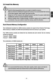
...before installing the memory to prevent hardware damage. ■ Memory modules have a foolproof design. DIMM3 - CAUTION 11 11 It is recommended that the motherboard supports the memory. Dual Channel DS/SS DS/SS DS/SS (DS : Double Side, SS : Single Side, - : No Memory) DS...SS Single Channel - - DS/SS - DS/SS Dual Channel DS/SS - DS/SS Single Channel - - Dual Channel Memory Configuration This motherboard provides four DDR2 memory sockets and supports Dual Channel Technology. A memory module can be used and please select dual channel first to insert the...
...before installing the memory to prevent hardware damage. ■ Memory modules have a foolproof design. DIMM3 - CAUTION 11 11 It is recommended that the motherboard supports the memory. Dual Channel DS/SS DS/SS DS/SS (DS : Double Side, SS : Single Side, - : No Memory) DS...SS Single Channel - - DS/SS - DS/SS Dual Channel DS/SS - DS/SS Single Channel - - Dual Channel Memory Configuration This motherboard provides four DDR2 memory sockets and supports Dual Channel Technology. A memory module can be used and please select dual channel first to insert the...

English Manual.
Page 19
... sides separated by a notch in one direction. Notch If you take a look at both ends of memory module, it has asymmetric pin counts on this motherboard. 2 CAUTION 112-Pin 128-Pin Installing a Memory !
... sides separated by a notch in one direction. Notch If you take a look at both ends of memory module, it has asymmetric pin counts on this motherboard. 2 CAUTION 112-Pin 128-Pin Installing a Memory !

English Manual.
Page 20
... insert the graphics card into the slot. 4. After installing all expansion cards, replace the chassis cover. 6. CAUTION 2 2-3 Install an Expansion Card ! ■ Make sure the motherboard supports the expansion card. Align the card with a screw. 5.
... insert the graphics card into the slot. 4. After installing all expansion cards, replace the chassis cover. 6. CAUTION 2 2-3 Install an Expansion Card ! ■ Make sure the motherboard supports the expansion card. Align the card with a screw. 5.
English Manual.
Page 21
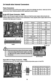
...12 PWR1 1 Pin No. 24 ! We recommend you using a 20-pin power supply, you are properly aligned with the connector on the motherboard. If you need to align the ATX power connector according to the picture. 20-Pin Power 8-pin ATX 12 V Power Connector : PWR2 Connect... been installed properly before applying the power supply. 24-pin ATX Power Connector : PWR1 PWR1 is secure. 2 CAUTION 2-4 Install other Internal Connectors Power Connectors This motherboard uses an ATX power supply. In order not to the CPU. 51 +12V GND 84 PWR2 Pin # 1 2 3 4 Definition GND GND GND GND Pin #...
...12 PWR1 1 Pin No. 24 ! We recommend you using a 20-pin power supply, you are properly aligned with the connector on the motherboard. If you need to align the ATX power connector according to the picture. 20-Pin Power 8-pin ATX 12 V Power Connector : PWR2 Connect... been installed properly before applying the power supply. 24-pin ATX Power Connector : PWR1 PWR1 is secure. 2 CAUTION 2-4 Install other Internal Connectors Power Connectors This motherboard uses an ATX power supply. In order not to the CPU. 51 +12V GND 84 PWR2 Pin # 1 2 3 4 Definition GND GND GND GND Pin #...

English Manual.
Page 22
... addition to the picture on the front panel. 12 VCC DD+ GND EMPTY VCC DD+ GND NC 9 10 F_USB 1/2/3 Floppy Disk Drive Connector : FLOPPY This motherboard includes a standard floppy disk drive (FDD) connector, supporting 360KB, 720KB, 1.2MB, 1.44MB, and 2.88MB FDDs. By connecting through a CD/ DVD audio cable. CAUTION ! It provides... the ATX power connector according to the six USB ports on the rear panel, this product also provides three 10-pin USB headers on its motherboard.
... addition to the picture on the front panel. 12 VCC DD+ GND EMPTY VCC DD+ GND NC 9 10 F_USB 1/2/3 Floppy Disk Drive Connector : FLOPPY This motherboard includes a standard floppy disk drive (FDD) connector, supporting 360KB, 720KB, 1.2MB, 1.44MB, and 2.88MB FDDs. By connecting through a CD/ DVD audio cable. CAUTION ! It provides... the ATX power connector according to the six USB ports on the rear panel, this product also provides three 10-pin USB headers on its motherboard.
English Manual.
Page 23
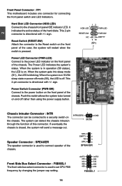
... 400 400 450 450 9 10 FSBSEL1 16 16 The system can be turned on the front panel of the chassis. 2 Front Panel Connector : FP1 This motherboard includes one connector for connecting the front panel switch and LED Indicators. PWR-LED -
... 400 400 450 450 9 10 FSBSEL1 16 16 The system can be turned on the front panel of the chassis. 2 Front Panel Connector : FP1 This motherboard includes one connector for connecting the front panel switch and LED Indicators. PWR-LED -

English Manual.
Page 24
... 2 EMPTY 3 IRRX 4 GND 5 IRTX IR Serial ATA Connectors : SATA_1/2/3/4/5/6 The Serial ATA connector is equipped with SATA Hard Disk or CD devices which support this motherboard. These fans can be controlled and monitored in "PC Health Status" section of the chassis. Fan Connectors : CPU_FAN, SYS_FAN, FAN1/2/3 There are five main fan...
... 2 EMPTY 3 IRRX 4 GND 5 IRTX IR Serial ATA Connectors : SATA_1/2/3/4/5/6 The Serial ATA connector is equipped with SATA Hard Disk or CD devices which support this motherboard. These fans can be controlled and monitored in "PC Health Status" section of the chassis. Fan Connectors : CPU_FAN, SYS_FAN, FAN1/2/3 There are five main fan...

English Manual.
Page 25
... . 18 18 Clear CMOS data is the fast way to go back to its original with pins 2-3 closed Clear CMOS Jumper: CLR_CMOS The motherboard uses CMOS RAM to use the various functions of this manual, pin 1 is simply labeled as BIOS data, date, time information, hardware password...and Pin 3 closed . 4. It can also be identified by changing the jumper settings. Go to BIOS Setup to modifying any jumper on this motherboard to modify them. This section explains how to store the basic hardware information (such as "1". 2. Users should read the following table explains different types...
... . 18 18 Clear CMOS data is the fast way to go back to its original with pins 2-3 closed Clear CMOS Jumper: CLR_CMOS The motherboard uses CMOS RAM to use the various functions of this manual, pin 1 is simply labeled as BIOS data, date, time information, hardware password...and Pin 3 closed . 4. It can also be identified by changing the jumper settings. Go to BIOS Setup to modifying any jumper on this motherboard to modify them. This section explains how to store the basic hardware information (such as "1". 2. Users should read the following table explains different types...
English Manual.
Page 34
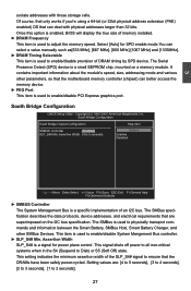
...:Select +/-/:Value F10:Save ESC:Exit F1:General Help F9:Optimized Defaults ► SMBUS Controller The System Management Bus is used to ensure that the motherboard memory controller (chipset) can deal with those storage cells. The SMBus is a specific implementation of the SLP_S4# signal to enable/disable PCI Express graphics port...
...:Select +/-/:Value F10:Save ESC:Exit F1:General Help F9:Optimized Defaults ► SMBUS Controller The System Management Bus is used to ensure that the motherboard memory controller (chipset) can deal with those storage cells. The SMBus is a specific implementation of the SLP_S4# signal to enable/disable PCI Express graphics port...


