English Manual.
Page 5
... damage to the motherboard and CPU due to high temperature. Normally it comes out as a motherboard, CPU or memory. ■ Ensure that the DC power supply is suggested to select high-quality, certified fans in serious damage to your device. ■ If there is any, when connecting USB, audio, 1394a, RS232 COM, IrDA or S/PDIF cables to the internal connectors on the motherboard, make sure their pinouts are matching with...
... damage to the motherboard and CPU due to high temperature. Normally it comes out as a motherboard, CPU or memory. ■ Ensure that the DC power supply is suggested to select high-quality, certified fans in serious damage to your device. ■ If there is any, when connecting USB, audio, 1394a, RS232 COM, IrDA or S/PDIF cables to the internal connectors on the motherboard, make sure their pinouts are matching with...

English Manual.
Page 6
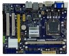
... Introduction Product Specifications 2 Layout...4 Back Panel Connectors 5 Chapter 2 Hardware Install Install the CPU and CPU Cooler 8 Install the Memory 11 Install an Expansion Card 13 Install other Internal Connectors 14 Jumpers 18 Chapter 3 BIOS Setup Enter BIOS Setup 20 Main Menu 20 System Information 22 Advanced BIOS Features 24 Fox Central Control Unit 27 Advanced Chipset Features 31 Integrated Peripherals 35 Power Management Setup 39 PC Health Status 41 BIOS Security Features 42 Load Optimal Defaults 43 Save & Exit Setup 43 Exit...
... Introduction Product Specifications 2 Layout...4 Back Panel Connectors 5 Chapter 2 Hardware Install Install the CPU and CPU Cooler 8 Install the Memory 11 Install an Expansion Card 13 Install other Internal Connectors 14 Jumpers 18 Chapter 3 BIOS Setup Enter BIOS Setup 20 Main Menu 20 System Information 22 Advanced BIOS Features 24 Fox Central Control Unit 27 Advanced Chipset Features 31 Integrated Peripherals 35 Power Management Setup 39 PC Health Status 41 BIOS Security Features 42 Load Optimal Defaults 43 Save & Exit Setup 43 Exit...
English Manual.
Page 9
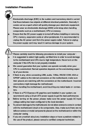
... Slots 1 x PCI Express x16 slot 1 x PCI Express x1 slot 2 x PCI slots Onboard Serial ATA 4 x SATA connectors 300MB/s data transfer rate Support hot plug and NCQ (Native Command Queuing ) USB Support hot plug Support up to 8 x USB 2.0 ports (4 rear panel ports, 2 onboard USB headers supporting 4 extra ports) Supports USB 2.0 protocol up to 480Mb/s Internal Connectors 1 x 24-pin ATX main power connector 1 x 4-pin ATX 12V power connector 1 x Floppy connector 1 x IDE connector 4 x SATA connectors 2 x USB 2.0 connectors (supporting 4 x USB devices) 1 x CPU fan header...
... Slots 1 x PCI Express x16 slot 1 x PCI Express x1 slot 2 x PCI slots Onboard Serial ATA 4 x SATA connectors 300MB/s data transfer rate Support hot plug and NCQ (Native Command Queuing ) USB Support hot plug Support up to 8 x USB 2.0 ports (4 rear panel ports, 2 onboard USB headers supporting 4 extra ports) Supports USB 2.0 protocol up to 480Mb/s Internal Connectors 1 x 24-pin ATX main power connector 1 x 4-pin ATX 12V power connector 1 x Floppy connector 1 x IDE connector 4 x SATA connectors 2 x USB 2.0 connectors (supporting 4 x USB devices) 1 x CPU fan header...
English Manual.
Page 10
...audio ports (G41MX 2.0/G41MX-F 2.0) 8-channel audio ports (G41MX-K 2.0) Hardware Monitor System voltage detection CPU/System temperature detection CPU/System fan speed detection CPU/System overheating shutdown CPU/System fan speed control PCI Express x16 Support 4GB/s (8GB/s concurrent) bandwidth Low power consumption and power management features Green Function Support ACPI (Advanced Configuration and Power Interface) Support S0 (normal), S1 (power on suspend), S3 (suspend to RAM), S4 (suspend to disk), and S5 (soft - 1 Back Panel 1 x PS/2 Keyboard port Connectors...
...audio ports (G41MX 2.0/G41MX-F 2.0) 8-channel audio ports (G41MX-K 2.0) Hardware Monitor System voltage detection CPU/System temperature detection CPU/System fan speed detection CPU/System overheating shutdown CPU/System fan speed control PCI Express x16 Support 4GB/s (8GB/s concurrent) bandwidth Low power consumption and power management features Green Function Support ACPI (Advanced Configuration and Power Interface) Support S0 (normal), S1 (power on suspend), S3 (suspend to RAM), S4 (suspend to disk), and S5 (soft - 1 Back Panel 1 x PS/2 Keyboard port Connectors...
English Manual.
Page 14
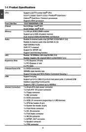
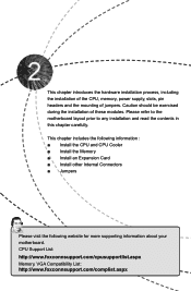
... for more supporting information about your motherboard. CPU Support List: http://www.foxconnsupport.com/cpusupportlist.aspx Memory, VGA Compatibility List: http://www.foxconnsupport.com/complist.aspx Please refer to the motherboard layout prior to any installation and read the contents in this chapter carefully. Caution should be exercised during the installation of jumpers. This chapter introduces the hardware installation process, including the installation of the CPU, memory, power supply, slots, pin headers and...
... for more supporting information about your motherboard. CPU Support List: http://www.foxconnsupport.com/cpusupportlist.aspx Memory, VGA Compatibility List: http://www.foxconnsupport.com/complist.aspx Please refer to the motherboard layout prior to any installation and read the contents in this chapter carefully. Caution should be exercised during the installation of jumpers. This chapter introduces the hardware installation process, including the installation of the CPU, memory, power supply, slots, pin headers and...
English Manual.
Page 20
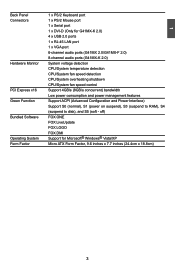
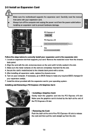
... Locate an expansion slot that came with a screw. 5. If necessary, go to BIOS Setup to the chassis back panel with your computer. PCI Express x1 PCI Express x16 PCI Follow the steps below to prevent hardware damage. Make sure the metal contacts on your expansion card. ■ Always turn off the computer and unplug the power cord from the chassis back panel. 2. After installing all expansion cards, replace the chassis...
... Locate an expansion slot that came with a screw. 5. If necessary, go to BIOS Setup to the chassis back panel with your computer. PCI Express x1 PCI Express x16 PCI Follow the steps below to prevent hardware damage. Make sure the metal contacts on your expansion card. ■ Always turn off the computer and unplug the power cord from the chassis back panel. 2. After installing all expansion cards, replace the chassis...

English Manual.
Page 23
... case; Reset Switch (RESET-SW) Attach the connector to be turned on the front panel of the chassis. IR/CIR Connector : IR/CIR This connector supports infrared wireless transmitting and receiving device. 16 16 1 +5V 2 EMPTY 3 IRRX 4 GND 5 IRTX IR/CIR the system will restart when the switch is directional with +/- Hard Disk LED Connector (HDD-LED) Connect to any IDE type of hard disk and CD/DVD ROM/RW drive. This 2-pin connector is off rather than using the power supply button. 1 + HDD-LED...
... case; Reset Switch (RESET-SW) Attach the connector to be turned on the front panel of the chassis. IR/CIR Connector : IR/CIR This connector supports infrared wireless transmitting and receiving device. 16 16 1 +5V 2 EMPTY 3 IRRX 4 GND 5 IRTX IR/CIR the system will restart when the switch is directional with +/- Hard Disk LED Connector (HDD-LED) Connect to any IDE type of hard disk and CD/DVD ROM/RW drive. This 2-pin connector is off rather than using the power supply button. 1 + HDD-LED...
English Manual.
Page 25
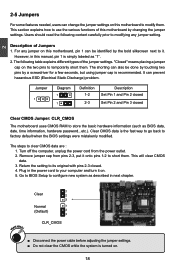
..., hardware password...etc.). This will clear CMOS data. 3. Go to BIOS Setup to short them. However, in the power cord to temporarily short them . Jumper 1 Diagram 1 1 Definition 1-2 2-3 Description Set Pin 1 and Pin 2 closed Set Pin 2 and Pin 3 closed . 4. Remove jumper cap from the power outlet. 2. Plug in this motherboard by the bold silkscreen next to it on the two pins to your computer and turn it . WARNING! 1 Clear 2 3 Normal 1 (Default) 2 3 CLR_CMOS ■ Disconnect the power cable before...
..., hardware password...etc.). This will clear CMOS data. 3. Go to BIOS Setup to short them. However, in the power cord to temporarily short them . Jumper 1 Diagram 1 1 Definition 1-2 2-3 Description Set Pin 1 and Pin 2 closed Set Pin 2 and Pin 3 closed . 4. Remove jumper cap from the power outlet. 2. Plug in this motherboard by the bold silkscreen next to it on the two pins to your computer and turn it . WARNING! 1 Clear 2 3 Normal 1 (Default) 2 3 CLR_CMOS ■ Disconnect the power cable before...
English Manual.
Page 27
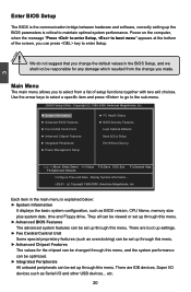
... default values in the main menu is critical to select from the change you made. v02.61 (c) Copyright 1985-2008, American Megatrends, Inc. 3 CAUTION Enter BIOS Setup The BIOS is the communication bridge between hardware and software, correctly setting up the BIOS parameters is explained below: ► System Information It displays the basic system configuration, such as BIOS version, CPU Name, memory size plus system date, time and Floppy drive. CMOS Setup Utility...
... default values in the main menu is critical to select from the change you made. v02.61 (c) Copyright 1985-2008, American Megatrends, Inc. 3 CAUTION Enter BIOS Setup The BIOS is the communication bridge between hardware and software, correctly setting up the BIOS parameters is explained below: ► System Information It displays the basic system configuration, such as BIOS version, CPU Name, memory size plus system date, time and Floppy drive. CMOS Setup Utility...
English Manual.
Page 28
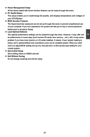
... Without Saving Do not change fan speeds, and displays temperatures and voltages of your system loading is to adjust BIOS setting one by one, trial and error, to find out the best setting for your current system. ► Save & Exit Setup Save setting values to optimal default may cause problem if you have more memory or I/O cards installed. It means, if your computer. 3 ► Power Management Setup All the items...
... Without Saving Do not change fan speeds, and displays temperatures and voltages of your system loading is to adjust BIOS setting one by one, trial and error, to find out the best setting for your current system. ► Save & Exit Setup Save setting values to optimal default may cause problem if you have more memory or I/O cards installed. It means, if your computer. 3 ► Power Management Setup All the items...
English Manual.
Page 31
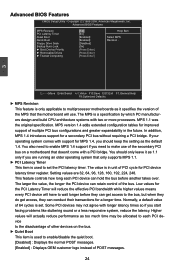
... item is set the PCI latency timer. The larger the value, the longer the PCI device can retain control of 64 cycles is used to enable/disable the quiet boot. [Disabled] : Displays the normal POST messages. [Enabled] : Displays OEM customer logo instead of other devices on a motherboard that the motherboard will have to wait longer before they can hold the bus before another takes over. Advanced BIOS Features CMOS Setup Utility - If...
... item is set the PCI latency timer. The larger the value, the longer the PCI device can retain control of 64 cycles is used to enable/disable the quiet boot. [Disabled] : Displays the normal POST messages. [Enabled] : Displays OEM customer logo instead of other devices on a motherboard that the motherboard will have to wait longer before they can hold the bus before another takes over. Advanced BIOS Features CMOS Setup Utility - If...
English Manual.
Page 34
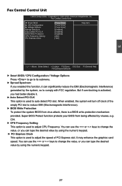
...:Optimized Defaults ► Smart BIOS / CPU Configuration / Voltage Options Press to go to its submenu. ► Spread Spectrum If you had better disable it can type the desired value by using the numeric keypad. 27 When enabled, the system will turn off clock of PCI Express slot. It may enhance the graphics card speed. But if overclocking is activated, you enabled this function, it . ► Auto Detect PCI CLK This option is used to auto detect PCI slot...
...:Optimized Defaults ► Smart BIOS / CPU Configuration / Voltage Options Press to go to its submenu. ► Spread Spectrum If you had better disable it can type the desired value by using the numeric keypad. 27 When enabled, the system will turn off clock of PCI Express slot. It may enhance the graphics card speed. But if overclocking is activated, you enabled this function, it . ► Auto Detect PCI CLK This option is used to auto detect PCI slot...
English Manual.
Page 36
... enable/disable the EIST (Processor Power Management, PPM) through this item. ! This item is used to insert code in memory by where application code can halt worm attacks, reducing the need for more information. 29 CAUTION Replacing older computers with Execute Disable Bit-enabled systems can execute and where it should be met, including CPU, chipset, motherboard, BIOS and operation system. It is used to enable/disable the Execute Disable Bit...
... enable/disable the EIST (Processor Power Management, PPM) through this item. ! This item is used to insert code in memory by where application code can halt worm attacks, reducing the need for more information. 29 CAUTION Replacing older computers with Execute Disable Bit-enabled systems can execute and where it should be met, including CPU, chipset, motherboard, BIOS and operation system. It is used to enable/disable the Execute Disable Bit...

English Manual.
Page 41
... Disk) or S5 (Soft Off) state. This signal shuts off power to all non-critical systems when in the S4 (Suspend to individual serial links in the PCI Express base specification. Setting values are superimposed on a system affects the amount of an I2C bus. The configuration of the PCI Express implementation on the I2C bus specification. The SMBus is used to 2 seconds] Enabled Disabled ASPM [Disabled] 3 Move Enter...
... Disk) or S5 (Soft Off) state. This signal shuts off power to all non-critical systems when in the S4 (Suspend to individual serial links in the PCI Express base specification. Setting values are superimposed on a system affects the amount of an I2C bus. The configuration of the PCI Express implementation on the I2C bus specification. The SMBus is used to 2 seconds] Enabled Disabled ASPM [Disabled] 3 Move Enter...

English Manual.
Page 43
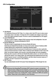
3 OnBoard Configuration CMOS Setup Utility - OnBoard Configuration OnBoard Configuration Help Item OnBoard Audio Controller [Enabled] Options OnBoard LAN Controller [Enabled] OnBoard LAN Boot ROM [Disabled] Enabled Disabled Move Enter:Select +/-/:Value F10:Save ESC:Exit F1:General Help F9:Optimized Defaults ► OnBoard Audio Controller This item is used to enable or disable the onboard Audio Controller. ► OnBoard LAN Controller This item is used to enable or disable...
3 OnBoard Configuration CMOS Setup Utility - OnBoard Configuration OnBoard Configuration Help Item OnBoard Audio Controller [Enabled] Options OnBoard LAN Controller [Enabled] OnBoard LAN Boot ROM [Disabled] Enabled Disabled Move Enter:Select +/-/:Value F10:Save ESC:Exit F1:General Help F9:Optimized Defaults ► OnBoard Audio Controller This item is used to enable or disable the onboard Audio Controller. ► OnBoard LAN Controller This item is used to enable or disable...
English Manual.
Page 45
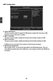
...USB Devices Enabled : option disables 1 Keyboard legacy support if no USB devices are many different emulation types of this USB device, such as floppy, hard disk and CDROM can set to auto or enabled. ► USB 1.1 Controller This item is used to enable or disable the Universal Host Controller Interface for USB. ► USB 2.0 Controller This item is used to enable or disable the Enhanced Host Controller Interface for USB devices on legacy OS. USB Configuration USB Configuration Help Item Module Version - 2.24.3-13.4 Enables support...
...USB Devices Enabled : option disables 1 Keyboard legacy support if no USB devices are many different emulation types of this USB device, such as floppy, hard disk and CDROM can set to auto or enabled. ► USB 1.1 Controller This item is used to enable or disable the Universal Host Controller Interface for USB. ► USB 2.0 Controller This item is used to enable or disable the Enhanced Host Controller Interface for USB devices on legacy OS. USB Configuration USB Configuration Help Item Module Version - 2.24.3-13.4 Enables support...
English Manual.
Page 46
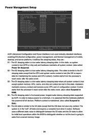
... wake latency sleeping state where all devices. S3 - Power Management Setup ACPI Suspend Type Power On after Power Fail HPET Resume by Ring Resume by LAN Resume by PCIE PME Resume by PCI Card Resume by USB Devices Resume by PS2 Keyboard Resume by PS2 Mouse Resume by ACPI. Copyright (C) 1985-2008, American Megatrends, Inc. Power Management Setup CMOS Setup Utility - The S1 sleeping state is an open industry standard interfaces enabling OS-directed configuration, power...
... wake latency sleeping state where all devices. S3 - Power Management Setup ACPI Suspend Type Power On after Power Fail HPET Resume by Ring Resume by LAN Resume by PCIE PME Resume by PCI Card Resume by USB Devices Resume by PS2 Keyboard Resume by PS2 Mouse Resume by ACPI. Copyright (C) 1985-2008, American Megatrends, Inc. Power Management Setup CMOS Setup Utility - The S1 sleeping state is an open industry standard interfaces enabling OS-directed configuration, power...

English Manual.
Page 48
... is used to enable or disable case open warning function. ► CPU/System Temperature The CPU/System temperature are automatically detected and displayed by the system. ► CPU Fan/System Fan Speed The CPU fan/System fan speed are automatically detected and displayed by the system. ► CPU Core/DRAM Voltage/+ 3.30V/+5.00V/+12.0V The current voltages are automatically detected and displayed by the system. ► System/CPU Smart Fan Control This option is used to set value, the motherboard will...
... is used to enable or disable case open warning function. ► CPU/System Temperature The CPU/System temperature are automatically detected and displayed by the system. ► CPU Fan/System Fan Speed The CPU fan/System fan speed are automatically detected and displayed by the system. ► CPU Core/DRAM Voltage/+ 3.30V/+5.00V/+12.0V The current voltages are automatically detected and displayed by the system. ► System/CPU Smart Fan Control This option is used to set value, the motherboard will...
English Manual.
Page 49
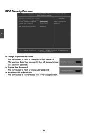
... item is used to install or change user password. ► Boot Sector Virus Protection This item is used to install or change the Change User Password [Press Enter] password. Boot Sector Virus Protection [Disabled] Move Enter:Select +/-/:Value F10:Save ESC:Exit F1:General Help F9:Optimized Defaults ► Change Supervisor Password This item is used to enable/disable boot sector virus protection. Copyright (C) 1985-2008, American Megatrends, Inc. Enter New Password : Enter New Password : 42 3 BIOS Security Features CMOS Setup Utility -
... item is used to install or change user password. ► Boot Sector Virus Protection This item is used to install or change the Change User Password [Press Enter] password. Boot Sector Virus Protection [Disabled] Move Enter:Select +/-/:Value F10:Save ESC:Exit F1:General Help F9:Optimized Defaults ► Change Supervisor Password This item is used to enable/disable boot sector virus protection. Copyright (C) 1985-2008, American Megatrends, Inc. Enter New Password : Enter New Password : 42 3 BIOS Security Features CMOS Setup Utility -
English Manual.
Page 52
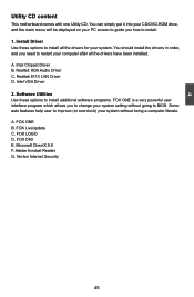
.../DVD-ROM drive, and the main menu will be displayed on your PC screen to guide you need to restart your computer after all the drivers for your system. You should install the drivers in order, and you how to BIOS. Microsoft DirectX 9.0 F. Intel Chipset Driver B. Some auto features help user to improve (or overclock) your system setting without being a computer literate. FOX DMI E. Adobe Acrobat Reader G. Install Driver Use these options...
.../DVD-ROM drive, and the main menu will be displayed on your PC screen to guide you need to restart your computer after all the drivers for your system. You should install the drivers in order, and you how to BIOS. Microsoft DirectX 9.0 F. Intel Chipset Driver B. Some auto features help user to improve (or overclock) your system setting without being a computer literate. FOX DMI E. Adobe Acrobat Reader G. Install Driver Use these options...


