
English Manual.
Page 5
... to come in your system, we recommend using a 24-pin ATX power supply to get the best performance. ■ Before turning on the computer if the CPU fan is not properly installed. ■ We cannot guarantee that the DC power supply is a PCI Express x16 graphics card installed in contact with the connectors on the motherboard. Normally it comes out as a motherboard, CPU or memory. ■ Ensure that your system can...
... to come in your system, we recommend using a 24-pin ATX power supply to get the best performance. ■ Before turning on the computer if the CPU fan is not properly installed. ■ We cannot guarantee that the DC power supply is a PCI Express x16 graphics card installed in contact with the connectors on the motherboard. Normally it comes out as a motherboard, CPU or memory. ■ Ensure that your system can...

English Manual.
Page 6
... Introduction Product Specifications 2 Layout...4 Back Panel Connectors 5 Chapter 2 Hardware Install Install the CPU and CPU Cooler 8 Install the Memory 11 Install an Expansion Card 13 Install other Internal Connectors 14 Jumpers 18 Chapter 3 BIOS Setup Enter BIOS Setup 20 Main Menu 20 System Information 22 Advanced BIOS Features 24 Fox Central Control Unit 26 Advanced Chipset Features 29 Integrated Peripherals 33 Power Management Setup 37 PC Health Status 39 BIOS Security Features 40 Load Optimal Defaults 41 Save & Exit Setup 41 Exit...
... Introduction Product Specifications 2 Layout...4 Back Panel Connectors 5 Chapter 2 Hardware Install Install the CPU and CPU Cooler 8 Install the Memory 11 Install an Expansion Card 13 Install other Internal Connectors 14 Jumpers 18 Chapter 3 BIOS Setup Enter BIOS Setup 20 Main Menu 20 System Information 22 Advanced BIOS Features 24 Fox Central Control Unit 26 Advanced Chipset Features 29 Integrated Peripherals 33 Power Management Setup 37 PC Health Status 39 BIOS Security Features 40 Load Optimal Defaults 41 Save & Exit Setup 41 Exit...

English Manual.
Page 9
... Slots 1 x PCI Express x16 slot 1 x PCI Express x1 slot 2 x PCI slots Onboard Serial ATA 4 x SATA connectors 300MB/s data transfer rate Support hot plug and NCQ (Native Command Queuing ) USB Support hot plug Support up to 8 x USB 2.0 ports (4 rear panel ports, 2 onboard USB headers supporting 4 extra ports) Supports USB 2.0 protocol up to 480Mb/s Internal Connectors 1 x 24-pin ATX main power connector 1 x 4-pin ATX 12V power connector 1 x Floppy connector 1 x IDE connector 4 x SATA connectors 2 x USB 2.0 connectors (supporting 4 x USB devices) 1 x CPU fan header...
... Slots 1 x PCI Express x16 slot 1 x PCI Express x1 slot 2 x PCI slots Onboard Serial ATA 4 x SATA connectors 300MB/s data transfer rate Support hot plug and NCQ (Native Command Queuing ) USB Support hot plug Support up to 8 x USB 2.0 ports (4 rear panel ports, 2 onboard USB headers supporting 4 extra ports) Supports USB 2.0 protocol up to 480Mb/s Internal Connectors 1 x 24-pin ATX main power connector 1 x 4-pin ATX 12V power connector 1 x Floppy connector 1 x IDE connector 4 x SATA connectors 2 x USB 2.0 connectors (supporting 4 x USB devices) 1 x CPU fan header...

English Manual.
Page 10
...x Chassis Intrusion Alarm header (INTR) Back Panel 1 x PS/2 Keyboard port Connectors 1 x PS/2 Mouse port 1 x Serial port 1 x Parallel port 4 x USB 2.0 ports 1 x RJ-45 LAN port 1 x VGA port 6-channel audio ports (G41MXE) 8-channel audio ports (G41MXE-K) Hardware Monitor System voltage detection CPU/System temperature detection CPU/System fan speed detection CPU/System overheating shutdown CPU/System fan speed control PCI Express x16 Support 4GB/s (8GB/s concurrent) bandwidth Low power consumption and power management features Green Function Support ACPI...
...x Chassis Intrusion Alarm header (INTR) Back Panel 1 x PS/2 Keyboard port Connectors 1 x PS/2 Mouse port 1 x Serial port 1 x Parallel port 4 x USB 2.0 ports 1 x RJ-45 LAN port 1 x VGA port 6-channel audio ports (G41MXE) 8-channel audio ports (G41MXE-K) Hardware Monitor System voltage detection CPU/System temperature detection CPU/System fan speed detection CPU/System overheating shutdown CPU/System fan speed control PCI Express x16 Support 4GB/s (8GB/s concurrent) bandwidth Low power consumption and power management features Green Function Support ACPI...

English Manual.
Page 11
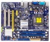
S/PDIF_OUT Connector 9. SATA Connectors 17. North Bridge: Intel ® G41 24. IR Connector 5. CD_IN Connector 10. TPM Connector 16. Front Panel Connector 18. CPU_FAN Header 23. PCI Express x1 Slot 6. Front USB Connectors 14. Speaker Connector 20. 24-pin ATX Power Connector 21. Front Audio Connector 11. Floppy Connector 12. INTR Connector 15. IDE Connector 19. 1 1-2 Layout 87 6 54 3 2 1 9 10 25 11 24 12 23 13 22 14 21 15 16 17 18 19 20 1. 4-pin ATX 12V Power Connector 2. COM2 Connector 4. PCI Slots 8. Clear CMOS Jumper Note : The...
S/PDIF_OUT Connector 9. SATA Connectors 17. North Bridge: Intel ® G41 24. IR Connector 5. CD_IN Connector 10. TPM Connector 16. Front Panel Connector 18. CPU_FAN Header 23. PCI Express x1 Slot 6. Front USB Connectors 14. Speaker Connector 20. 24-pin ATX Power Connector 21. Front Audio Connector 11. Floppy Connector 12. INTR Connector 15. IDE Connector 19. 1 1-2 Layout 87 6 54 3 2 1 9 10 25 11 24 12 23 13 22 14 21 15 16 17 18 19 20 1. 4-pin ATX 12V Power Connector 2. COM2 Connector 4. PCI Slots 8. Clear CMOS Jumper Note : The...

English Manual.
Page 14
... introduces the hardware installation process, including the installation of the CPU, memory, power supply, slots, pin headers and the mounting of these modules. This chapter includes the following information : ■ Install the CPU and CPU Cooler ■ Install the Memory ■ Install an Expansion Card ■ Install other Internal Connectors ■ Jumpers Please visit the following website for more supporting information about your motherboard. CPU Support List: http://www.foxconnsupport.com/cpusupportlist.aspx Memory, VGA Compatibility List: http://www...
... introduces the hardware installation process, including the installation of the CPU, memory, power supply, slots, pin headers and the mounting of these modules. This chapter includes the following information : ■ Install the CPU and CPU Cooler ■ Install the Memory ■ Install an Expansion Card ■ Install other Internal Connectors ■ Jumpers Please visit the following website for more supporting information about your motherboard. CPU Support List: http://www.foxconnsupport.com/cpusupportlist.aspx Memory, VGA Compatibility List: http://www...

English Manual.
Page 20
... contacts on your expansion card(s). 7. PCI Express x1 PCI Express x16 PCI Follow the steps below to make any required BIOS changes for your computer. Make sure the graphics card is fully seated in the slot. 3. Align the card with a screw. 5. Remove the metal slot cover from the slot. 13 13 Carefully read the manual that supports your expansion card in your expansion card. ■ Always turn off the computer...
... contacts on your expansion card(s). 7. PCI Express x1 PCI Express x16 PCI Follow the steps below to make any required BIOS changes for your computer. Make sure the graphics card is fully seated in the slot. 3. Align the card with a screw. 5. Remove the metal slot cover from the slot. 13 13 Carefully read the manual that supports your expansion card in your expansion card. ■ Always turn off the computer...

English Manual.
Page 23
... connect with a 9-pin D-sub connector at one serial RS232 COM port for connecting the front panel switch and LED Indicators. User must purchase another end with 10-pin female connector to connect with the external RS232 device and another RS232 cable with COM2 connector in the motherboard. Hard Disk LED Connector (HDD-LED) Connect to any IDE type of hard disk and CD/DVD ROM/RW drive. 1 + HDD-LED - 2 + PWR-LED - When the system gets into sleep mode (S1) , the LED is directional with +/- This 2-pin connector is on. Power Switch Connector...
... connect with a 9-pin D-sub connector at one serial RS232 COM port for connecting the front panel switch and LED Indicators. User must purchase another end with 10-pin female connector to connect with the external RS232 device and another RS232 cable with COM2 connector in the motherboard. Hard Disk LED Connector (HDD-LED) Connect to any IDE type of hard disk and CD/DVD ROM/RW drive. 1 + HDD-LED - 2 + PWR-LED - When the system gets into sleep mode (S1) , the LED is directional with +/- This 2-pin connector is on. Power Switch Connector...

English Manual.
Page 25
... password...etc.). This will clear CMOS data. 3. Go to BIOS Setup to configure new system as described in the power cord to your computer and turn it onto pins 1-2 to store the basic hardware information (such as "1". 2. Description of the jumper settings. The steps to factory default when the BIOS settings were mistakenly modified. Return the setting to its original with pins 2-3 closed Clear CMOS Jumper: CLR_CMOS The motherboard uses CMOS RAM to short...
... password...etc.). This will clear CMOS data. 3. Go to BIOS Setup to configure new system as described in the power cord to your computer and turn it onto pins 1-2 to store the basic hardware information (such as "1". 2. Description of the jumper settings. The steps to factory default when the BIOS settings were mistakenly modified. Return the setting to its original with pins 2-3 closed Clear CMOS Jumper: CLR_CMOS The motherboard uses CMOS RAM to short...

English Manual.
Page 27
... menu. There are boot up settings. ► Fox Central Control Unit Some special proprietary features (such as Serial I /O devices such as overclocking) can be set up through this menu. 3 CAUTION Enter BIOS Setup The BIOS is the communication bridge between hardware and software, correctly setting up through this menu. ► Advanced Chipset Features The values for any damage which resulted from a list of the screen, you can press key to enter Setup...
... menu. There are boot up settings. ► Fox Central Control Unit Some special proprietary features (such as Serial I /O devices such as overclocking) can be set up through this menu. 3 CAUTION Enter BIOS Setup The BIOS is the communication bridge between hardware and software, correctly setting up through this menu. ► Advanced Chipset Features The values for any damage which resulted from a list of the screen, you can press key to enter Setup...

English Manual.
Page 28
... password before boot or access to Setup. ► Load Optimal Defaults The optimal performance settings can be loaded through this menu. It means, if your current system. ► Save & Exit Setup Save setting values to CMOS and exit. ► Exit Without Saving Do not change fan speeds, and displays temperatures and voltages of your CPU/System. ► BIOS Security Features The Supervisor/User password can be set up through this menu to prevent unauthorized use...
... password before boot or access to Setup. ► Load Optimal Defaults The optimal performance settings can be loaded through this menu. It means, if your current system. ► Save & Exit Setup Save setting values to CMOS and exit. ► Exit Without Saving Do not change fan speeds, and displays temperatures and voltages of your CPU/System. ► BIOS Security Features The Supervisor/User password can be set up through this menu to prevent unauthorized use...

English Manual.
Page 31
... only leave it specifies the version of the bus. You also need to enable MPS 1.4 support if you need to the disadvantage of other devices on a motherboard that doesn't come with two or more processors. Normally, a default value of the secondary PCI bus on the bus. ► Quiet Boot This item is used to enable/disable the quiet boot. [Disabled] : Displays the normal POST messages. [Enabled] : Displays OEM customer logo instead...
... only leave it specifies the version of the bus. You also need to enable MPS 1.4 support if you need to the disadvantage of other devices on a motherboard that doesn't come with two or more processors. Normally, a default value of the secondary PCI bus on the bus. ► Quiet Boot This item is used to enable/disable the quiet boot. [Disabled] : Displays the normal POST messages. [Enabled] : Displays OEM customer logo instead...

English Manual.
Page 33
...:Optimized Defaults ► Smart BIOS / CPU Configuration Press to go to its submenu. ► Spread Spectrum If you can use the or keys to change the value, or you enabled this function, it . ► Auto Detect PCI CLK This option is used to adjust the speed of the empty PCI slot to auto detect PCI slot. It may enhance the graphics card speed. When enabled, the system will turn off clock of PCI Express slot. 3 Fox Central Control Unit CMOS Setup Utility -
...:Optimized Defaults ► Smart BIOS / CPU Configuration Press to go to its submenu. ► Spread Spectrum If you can use the or keys to change the value, or you enabled this function, it . ► Auto Detect PCI CLK This option is used to adjust the speed of the empty PCI slot to auto detect PCI slot. It may enhance the graphics card speed. When enabled, the system will turn off clock of PCI Express slot. 3 Fox Central Control Unit CMOS Setup Utility -

English Manual.
Page 35
.... CPU Configuration CMOS Setup Utility - Copyright (C) 1985-2008, American Megatrends, Inc. CPU Configuration CPU Configuration Help Item Module Version : 3F.0F Sets the ratio Manufacturer : Intel between CPU Core Clock and the FSB Frequency. ► C1E Support C1E represents Enhanced HALT State. It is disabled. Set Limit CPUID MaxVal to enable or disable CPUID maximum value limit configuration. Execute Disable Bit allows the processor to reduce power consumption when in memory by where application code can enable/disable the...
.... CPU Configuration CMOS Setup Utility - Copyright (C) 1985-2008, American Megatrends, Inc. CPU Configuration CPU Configuration Help Item Module Version : 3F.0F Sets the ratio Manufacturer : Intel between CPU Core Clock and the FSB Frequency. ► C1E Support C1E represents Enhanced HALT State. It is disabled. Set Limit CPUID MaxVal to enable or disable CPUID maximum value limit configuration. Execute Disable Bit allows the processor to reduce power consumption when in memory by where application code can enable/disable the...

English Manual.
Page 39
...] Enabled Disabled ASPM [Disabled] 3 Move Enter:Select +/-/:Value F10:Save ESC:Exit F1:General Help F9:Optimized Defaults ► SMBUS Controller The System Management Bus is used to ensure that the DRAMs have been safely power-cycled. The configuration of the PCI Express implementation on the overall system power policy, the hardware capabilities of the Link, and the latency of the Link. This item is a specific...
...] Enabled Disabled ASPM [Disabled] 3 Move Enter:Select +/-/:Value F10:Save ESC:Exit F1:General Help F9:Optimized Defaults ► SMBUS Controller The System Management Bus is used to ensure that the DRAMs have been safely power-cycled. The configuration of the PCI Express implementation on the overall system power policy, the hardware capabilities of the Link, and the latency of the Link. This item is a specific...

English Manual.
Page 41
...Move Enter:Select +/-/:Value F10:Save ESC:Exit F1:General Help F9:Optimized Defaults ► OnBoard Audio Controller This item is used to enable or disable the onboard Audio Controller. ► OnBoard LAN Controller This item is used to enable or disable the onboard LAN controller. ► OnBoard LAN Boot ROM This item is used to be booted remotely. 34 By installing a boot ROM in the network board, you set up a diskless workstation on the network to enable or disable the onboard LAN boot optional ROM. 3 OnBoard Configuration CMOS Setup Utility...
...Move Enter:Select +/-/:Value F10:Save ESC:Exit F1:General Help F9:Optimized Defaults ► OnBoard Audio Controller This item is used to enable or disable the onboard Audio Controller. ► OnBoard LAN Controller This item is used to enable or disable the onboard LAN controller. ► OnBoard LAN Boot ROM This item is used to be booted remotely. 34 By installing a boot ROM in the network board, you set up a diskless workstation on the network to enable or disable the onboard LAN boot optional ROM. 3 OnBoard Configuration CMOS Setup Utility...

English Manual.
Page 43
... have a USB keyboard or mouse, set to auto or enabled. ► USB 1.1 Controller This item is used to enable or disable the Universal Host Controller Interface for USB. ► USB 2.0 Controller This item is used to enable the support for USB. 36 Copyright (C) 1985-2008, American Megatrends, Inc. AUTO USB Devices Enabled : option disables None legacy support if no USB devices are Legacy USB Support [E nable d] connected. 3 USB Configuration CMOS Setup Utility - USB Configuration USB Configuration Help Item Module Version - 2.24...
... have a USB keyboard or mouse, set to auto or enabled. ► USB 1.1 Controller This item is used to enable or disable the Universal Host Controller Interface for USB. ► USB 2.0 Controller This item is used to enable the support for USB. 36 Copyright (C) 1985-2008, American Megatrends, Inc. AUTO USB Devices Enabled : option disables None legacy support if no USB devices are Legacy USB Support [E nable d] connected. 3 USB Configuration CMOS Setup Utility - USB Configuration USB Configuration Help Item Module Version - 2.24...

English Manual.
Page 44
... to RAM) S4 - Power Management Setup CMOS Setup Utility - CPU, cache, and chip set ) and hardware maintains all devices. Control starts from the processor's reset vector after the wake event. (also called Power On Suspend) S2 - Platform context is maintained. (also called Suspend to wake from the processor's reset vector after Power Fail HPET Resume by Ring Resume by LAN Resume by PCIE PME Resume by PCI Card Resume by USB Devices Resume by PS2 Keyboard Resume...
... to RAM) S4 - Power Management Setup CMOS Setup Utility - CPU, cache, and chip set ) and hardware maintains all devices. Control starts from the processor's reset vector after the wake event. (also called Power On Suspend) S2 - Platform context is maintained. (also called Suspend to wake from the processor's reset vector after Power Fail HPET Resume by Ring Resume by LAN Resume by PCIE PME Resume by PCI Card Resume by USB Devices Resume by PS2 Keyboard Resume...

English Manual.
Page 46
... V 90 oC/194 oF VBAT :3.284 V CPU Smart Fan Control [Disabled] System Smart Fan Control [Disabled] Move Enter:Select +/-/:Value F10:Save ESC:Exit F1:General Help F9:Optimized Defaults ► Warning Temperature This option is used to set value, the system will send out warning information. ► Shutdown Temperature This item is used to enable or disable smart fan function. 39 Copyright (C) 1985-2008, American Megatrends, Inc. 3 PC Health Status CMOS Setup Utility -
... V 90 oC/194 oF VBAT :3.284 V CPU Smart Fan Control [Disabled] System Smart Fan Control [Disabled] Move Enter:Select +/-/:Value F10:Save ESC:Exit F1:General Help F9:Optimized Defaults ► Warning Temperature This option is used to set value, the system will send out warning information. ► Shutdown Temperature This item is used to enable or disable smart fan function. 39 Copyright (C) 1985-2008, American Megatrends, Inc. 3 PC Health Status CMOS Setup Utility -

English Manual.
Page 50
... E. Install Driver Use these options to install additional software programs. FOX ONE is a very powerful user interface program which allows you need to restart your system without going to change your system setting without being a computer literate. Norton Internet Security 43 43 You can simply put it into your CD/DVD-ROM drive, and the main menu will be displayed on your system. Intel VGA Driver 2. Realtek HDA Audio Driver...
... E. Install Driver Use these options to install additional software programs. FOX ONE is a very powerful user interface program which allows you need to restart your system without going to change your system setting without being a computer literate. Norton Internet Security 43 43 You can simply put it into your CD/DVD-ROM drive, and the main menu will be displayed on your system. Intel VGA Driver 2. Realtek HDA Audio Driver...


